Page 802 of 2572

G26185
ECM
NEOE5
A20293
4.5 to 14 V
Below 1 V20 V/DIV, 1 ms/DIV Pulse
Generation
05-820
- DIAGNOSTICSABS WITH EBD & BA & TRAC & VSC SYSTEM
1010 Author�: Date�:
2 INSPECT ECM TERMINAL VOLTAGE(NEO TERMINAL)
(a) Reconnect the ECM connector and the skid control ECU
connector.
(b) Check the signal waveform between terminal NEO
(E5-17) of the ECM and body ground for the engine
conditions below.
OK:
Tester ConnectionEngine ConditionSpecified condition
E5-17 (NEO) - Body
groundOFF (Ignition switch ON)4.5 to 14 V or below 1 V
E5-17 (NEO) - Body
groundON (Idling)Pulse generation
(4.5 to 14 V e below 1 V)
NG REPLACE ECM
OK
3 CHECK IF SKID CONTROL ECU CONNECTOR IS SECURELY CONNECTED
NG CONNECT CONNECTOR TO ECU
OK
4 RECONFIRM DTC
(a) Clear the DTCs (see page 05-765).
(b) Turn the ignition switch to the ON position.
(c) Are the same DTCs recorded?
NO PROCEED TO NEXT CIRCUIT INSPECTION
SHOWN IN PROBLEM SYMPTOMS TABLE
(SEE PAGE 05-786)
YES
REPLACE ABS & TRACTION ACTUATOR ASSY(SEE PAGE 32-37)
Page 805 of 2572
 (-)(+)
(-)
S14
Steering Angle Sensor
(harness side connector)
- DIAGNOSTICSABS WITH EBD & BA & TRAC & VSC SYSTEM
05-823
1013 Author�: Date�:
INSPECTION PROCEDURE
HINT:
�When U012")
G26292
IG1
ESSBAT
(+) (-)(+)
(-)
S14
Steering Angle Sensor
(harness side connector)
- DIAGNOSTICSABS WITH EBD & BA & TRAC & VSC SYSTEM
05-823
1013 Author�: Date�:
INSPECTION PROCEDURE
HINT:
�When U0121/94, U0123/62, U0124/95 or U0126/63 are output together with C1231/31, inspect and
repair the trouble areas indicated by U0121/94, U0123/62, U0124/95 or U0126/63 first.
�When the speed sensor or the yaw rate sensor has trouble, DTCs for the steering angle sensor may
be output even when the steering angle sensor is normal. When DTCs for the speed sensor or yaw
rate sensor are output together with other DTCs for the steering angle sensor, inspect and repair the
speed sensor and yaw rate sensor first, and then inspect and repair the steering angle sensor.
�Start the inspection from step 1 when using the hand-held tester and start from step 2 when not using
the hand-held tester.
1 READ VALUE OF HAND-HELD TESTER(STEERING ANGLE SENSOR)
(a) Connect the hand-held tester to the DLC3.
(b) Start the engine.
(c) Select the DATA LIST mode on the hand-held tester.
(d) Check that the steering angle value of the steering angle sensor indicated on the hand-held tester,
changes when the steering wheel is turned.
ItemMeasurement Item /
Range (Display)Normal Condition
STEERING ANGSteering sensor/
Min.: -1152 deg, Max.: 1150.875 degMin.: -128 deg/s
Max.: 128 deg/s
OK:
Steering angle value should change.
OK REPLACE ABS & TRACTION ACTUATOR ASSY
(SEE PAGE 32-37)
NG
2 CHECK TERMINAL VOLTAGE(STEERING ANGLE SENSOR CONNECTOR)
(a) Remove the steering wheel and the column lower cover.
(b) Disconnect the steering angle sensor connector S14.
(c) Turn the ignition switch to the ON position.
(d) Measure the voltage according to the value(s) in the table
below.
Standard:
Tester ConnectionSpecified Condition
S14-1 (IG1) - S14-2 (ESS)10 to 14 V
S14-3 (BAT) - S14-2 (ESS)10 to 14 V
NG REPAIR OR REPLACE HARNESS OR
CONNECTOR
OK
REPLACE STEERING ANGLE SENSOR
Page 811 of 2572

S27
G24767
GND1
Skid Control ECU
(harness side connector)
S27
- DIAGNOSTICSABS WITH EBD & BA & TRAC & VSC SYSTEM
05-829
1019 Author�: Date�:")
G24767
GND1IG1
Skid Control ECU
(harness side connector)
S27
G24767
GND1
Skid Control ECU
(harness side connector)
S27
- DIAGNOSTICSABS WITH EBD & BA & TRAC & VSC SYSTEM
05-829
1019 Author�: Date�:
3 INSPECT SKID CONTROL ECU TERMINAL VOLTAGE(IG1 TERMINAL)
WHEN USING HAND-HELD TESTER:
(a) Connect the hand-held tester to the DLC3.
(b) Start the engine.
(c) Select the DATA LIST mode on the hand-held tester.
(d) Read the voltage condition output from the ECU displayed on the hand-held tester.
ItemMeasurement Item /
Range (Display)Normal Condition
IG VOLTAGEECU power supply voltage /
TOO LOW / NORMALNORMAL: 9.5 V or over
TOO LOW: Below 9.5 V
OK:
ºNormalº is displayed.
WHEN NOT USING HAND-HELD TESTER:
(a) Disconnect the skid control ECU connector S27.
(b) Turn the ignition switch to the ON position.
(c) Measure the voltage according to the value(s) in the table
below.
Standard:
Tester ConnectionSpecified Condition
S27-46 (IG1) - S27-32 (GND1)10 to 14 V
NG Go to step 4
OK
REPLACE ABS & TRACTION ACTUATOR ASSY (SEE PAGE 32-37)
4 INSPECT SKID CONTROL ECU CONNECTOR(GND TERMINAL CONTINUITY)
(a) Disconnect the skid control ECU connector S27.
(b) Measure the resistance according to the value(s) in the
table below.
Standard:
Tester ConnectionSpecified Condition
S27-32 (GND1) - Body groundBelow 1 W
NG REPAIR OR REPLACE HARNESS OR
CONNECTOR (GND TERMINAL - BODY
GROUND)
OK
CHECK AND REPAIR HARNESS AND CONNECTOR (IG1 TERMINAL - BATTERY)
Page 812 of 2572

05-830
- DIAGNOSTICSABS WITH EBD & BA & TRAC & VSC SYSTEM
1020 Author�: Date�:
DTC C1246/46 MALFUNCTION IN MASTER CYLINDER
PRESSURE SENSOR
CIRCUIT DESCRIPTION
Master cylinder pressure sensor is connected to the skid control ECU in the actuator.
DTC No.DTC Detecting ConditionTrouble Area
C1246/46
When any of the following (1 to 5) is detected:
(1) All the following conditions continues for at least 30 se-
conds.
�Vehicle speed is more than 4 mph (7 km/h).
�PMC terminal voltage does not change by more than
0.005 V once it exceeds 0.86 V.
(2) PMC terminal receives interference at least 7 times
within 5 sec.
(3) All the following conditions continues for at least 1.2
seconds.
�Stop switch is OFF.
�PMC terminal voltage is more than 0.86 V or less than 0.3
V.
(4) All the following conditions continues for at least 1.2
seconds.
�IG1 terminal voltage is between 9.5 and 17.2 V.
�VCM terminal voltage is not within 4.4 and 5.6 V.
(5) All the following conditions continues for at least 1.2
seconds.
�VCM terminal voltage is between 4.4 and 5.6 V.
�PMC terminal voltage is not within 0.14 and 4.85 V.
�Master cylinder pressure sensor
�Master cylinder pressure sensor circuit
INSPECTION PROCEDURE
HINT:
Start the inspection from step 1 when using the hand-held tester and start from step 2 when not using the
hand-held tester.
1 READ VALUE OF HAND-HELD TESTER(MASTER CYLINDER PRESSURE
SENSOR)
(a) Connect the hand-held tester to the DLC3.
(b) Start the engine.
(c) Select the DATA LIST mode on the hand-held tester.
ItemMeasurement Item /
Range (Display)Normal Condition
MAS CYL PRS 1Master cylinder pressure sensor 1
reading / min.: 0 V, max.: 5 VWhen brake pedal is released : 0.3 to
0.9 V
(d) Check that the brake fluid pressure value of the master cylinder pressure sensor indicated on the
hand-held tester, changes when the brake pedal is depressed.
Standard:
Brake fluid pressure value should change.
NG Go to step 2
OK
REPLACE ABS & TRACTION ACTUATOR ASSY (SEE PAGE 32-37)
05H3Q-02
Page 818 of 2572

S27
05-836
- DIAGNOSTICSABS WITH EBD & BA & TRAC & VSC SYSTEM
1026 Author�: Date�:
INSPECTION PROCEDURE
HINT:
Start the inspection from step 1 in c")
G24767GND2
Skid Control ECU
(harness side connector)
S27
05-836
- DIAGNOSTICSABS WITH EBD & BA & TRAC & VSC SYSTEM
1026 Author�: Date�:
INSPECTION PROCEDURE
HINT:
Start the inspection from step 1 in case of using the hand-held tester and start from step 2 in case of not
using the hand-held tester.
1 PERFORM ACTIVE TEST BY HAND-HELD TESTER(ABS MOTOR RELAY
OPERATION)
(a) Connect the hand-held tester to the DLC3.
(b) Start the engine.
(c) Select the ACTIVE TEST mode on the hand-held tester.
(d) Check the operation sound of the ABS motor individually when operating it with the hand-held tester.
ItemVehicle Condition / Test DetailsVehicle Condition / Test Details
ABS MOT RELAYABS motor relay / ON or OFFON: Motor relay ON
OK:
The operation sound of the ABS motor should be heard.
NG Go to step 2
OK
REPLACE ABS & TRACTION ACTUATOR ASSY (SEE PAGE 32-37)
2 INSPECT HARNESS AND CONNECTOR(GND2 OF SKID CONTROL ECU AND
BODY GROUND)
(a) Disconnect the skid control ECU connector.
(b) Measure the resistance according to the value(s) in the
table below.
Standard:
Tester ConnectionSpecified Condition
S27-1 (GND2) - Body groundBelow 1 W
NG REPAIR OR REPLACE HARNESS OR
CONNECTOR
OK
REPLACE ABS & TRACTION ACTUATOR ASSY (SEE PAGE 32-37)
Page 840 of 2572

Y
A85675
A81699A87763
Wire Harness Side
V2
VSV for IAC Valve No. 2
E7
ECM
ACIS
A85448
A90291A92391
Wire Harness Side
V2
VSV for IAC Valve No. 2
EFI Relay
Engine Room J/B
- DIAGNOSTICSSFI SYSTEM (3MZ-FE)
05-663
853 Author�: Date�:
2005 HIGHLANDER REPAIR MANUAL (RM1144U)
3 CHECK WIRE HARNESS (VSV FOR IAC VALVE NO. 2 - ECM, VSF FOR IAC VALVE
NO. 2 - EFI RELAY)
(a) Check the wire harness between the VSV and ECM.
(1) Disconnect the V2 VSV connector.
(2) Disconnect the E7 ECM connector.
(3) Check the resistance of the wire harness side con-
nectors.
Standard:
Tester ConnectionSpecified Condition
V2-2 - E7-15 (ACIS)Below 1 W
V2-2 or E7-15 (ACIS) - Body ground10 kW or higher
(b) Check the wire harness between the VSV and EFI relay.
(1) Disconnect the V2 VSV connector.
(2) Remove the EFI relay from the engine room J/B.
(3) Check the resistance of the wire harness side con-
nectors.
Standard:
Tester ConnectionSpecified Condition
V2-1 - J/B EFI relay terminal 3Below 1 W
NG REPAIR OR REPLACE HARNESS AND
CONNECTOR
OK
Page 842 of 2572
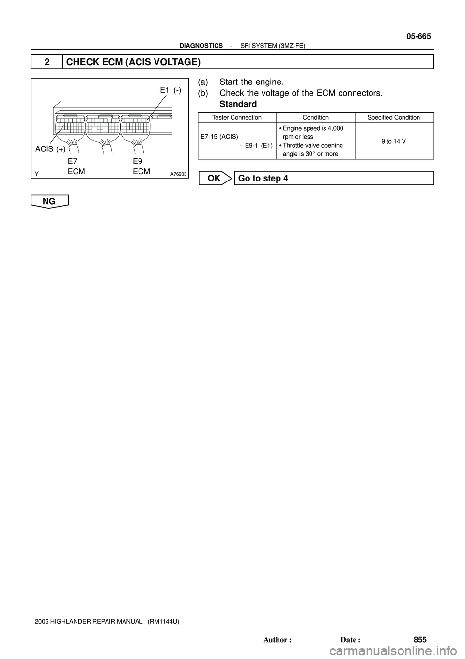
A76903
E1 (-)
E9
ECM
ACIS (+)
E7
ECM
- DIAGNOSTICSSFI SYSTEM (3MZ-FE)
05-665
855 Author�: Date�:
2005 HIGHLANDER REPAIR MANUAL (RM1144U)
2 CHECK ECM (ACIS VOLTAGE)
(a) Start the engine.
(b) Check the voltage of the ECM connectors.
Standard
Tester ConnectionConditionSpecified Condition
E7-15 (ACIS)
- E9-1 (E1)
�Engine speed is 4,000
rpm or less
�Throttle valve opening
angle is 30� or more
9 to 14 V
OK Go to step 4
NG
Page 843 of 2572

Y
A85675
A81699A87763
Wire Harness Side
V2
VSV for IAC Valve No. 2
E7
ECM
ACIS
A85448
A90291A92391
Wire Harness Side
V2
VSV for IAC Valve No. 2
EFI Relay
Engine Room J/B
05-666
- DIAGNOSTICSSFI SYSTEM (3MZ-FE)
856 Author�: Date�:
2005 HIGHLANDER REPAIR MANUAL (RM1144U)
3 CHECK WIRE HARNESS (VSV FOR IAC VALVE NO. 2 - ECM, VSV FOR IAC VALVE
NO.2 - EFI RELAY)
(a) Check the wire harness between the VSV and ECM.
(1) Disconnect the V2 VSV connector.
(2) Disconnect the E7 ECM connector.
(3) Check the resistance of the wire harness side con-
nectors.
Standard:
Tester ConnectionSpecified Condition
V2-2 - E7-15 (ACIS)Below 1 W
V2-2 or E7-15 (ACIS) - Body ground10 kW or higher
(b) Check the wire harness between the VSV and EFI relay.
(1) Disconnect the V2 VSV connector.
(2) Remove the EFI relay from the engine room J/B.
(3) Check the resistance OF the wire harness side con-
nectors.
Standard:
Tester ConnectionSpecified Condition
V2-1 (VSV for ACIS) - J/B EFI relay terminal 3Below 1 W
NG REPAIR OR REPLACE HARNESS AND
CONNECTOR
OK