Page 847 of 2572
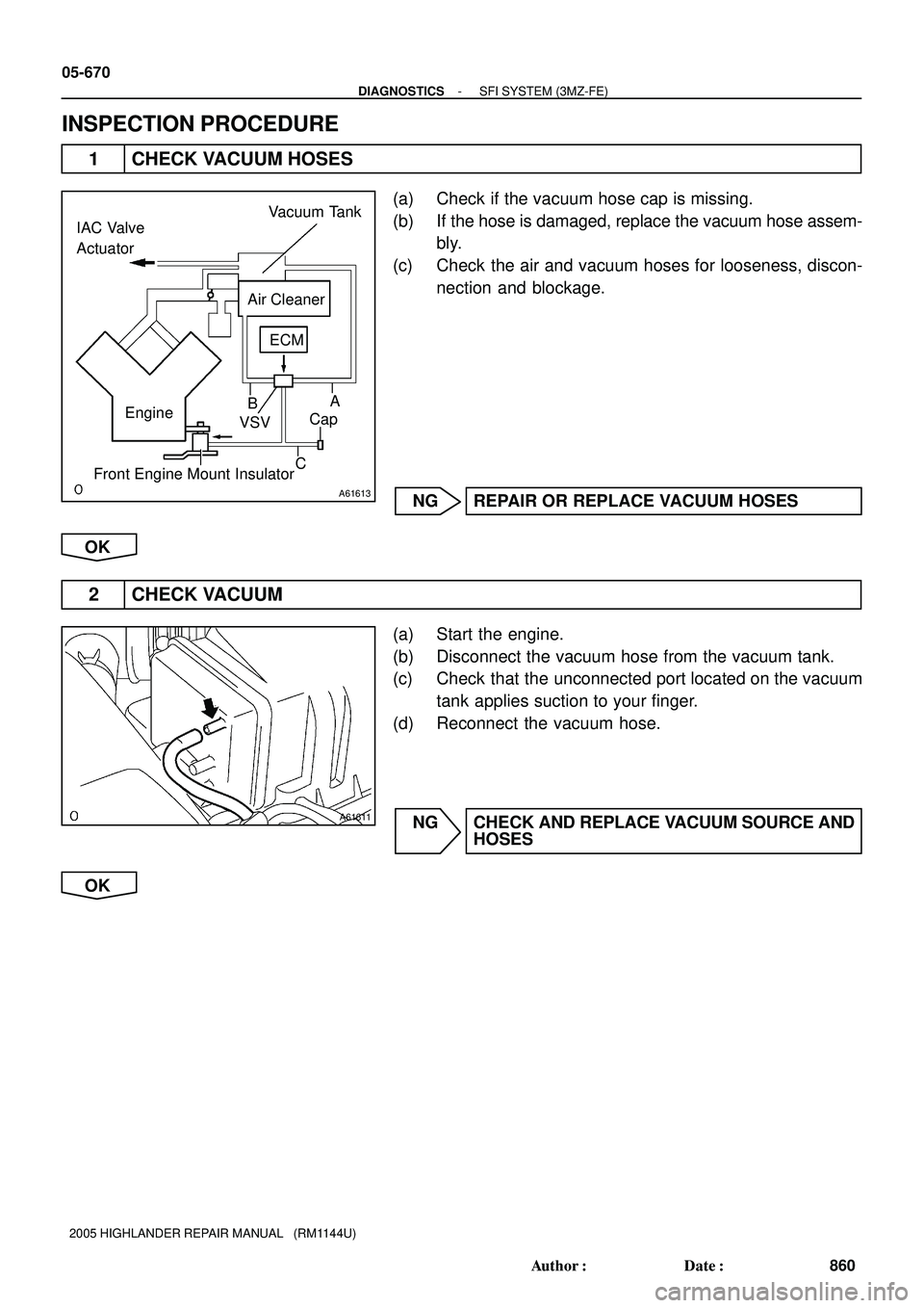
A61613
A
C EngineB IAC Valve
Actuator
Air Cleaner
Front Engine Mount InsulatorVSVCap ECM Vacuum Tank
A61611
05-670
- DIAGNOSTICSSFI SYSTEM (3MZ-FE)
860 Author�: Date�:
2005 HIGHLANDER REPAIR MANUAL (RM1144U)
INSPECTION PROCEDURE
1 CHECK VACUUM HOSES
(a) Check if the vacuum hose cap is missing.
(b) If the hose is damaged, replace the vacuum hose assem-
bly.
(c) Check the air and vacuum hoses for looseness, discon-
nection and blockage.
NG REPAIR OR REPLACE VACUUM HOSES
OK
2 CHECK VACUUM
(a) Start the engine.
(b) Disconnect the vacuum hose from the vacuum tank.
(c) Check that the unconnected port located on the vacuum
tank applies suction to your finger.
(d) Reconnect the vacuum hose.
NG CHECK AND REPLACE VACUUM SOURCE AND
HOSES
OK
Page 849 of 2572

862 Author�: Date�:
2005 HIGHL")
A87797
Wire Harness Side
V5
VSV for ACM
E9
ECM
ACM
A85448
A90291A92392
Wire Harness Side
V5
VSV for ACM
EFI Relay
Engine Room J/B
05-672
- DIAGNOSTICSSFI SYSTEM (3MZ-FE)
862 Author�: Date�:
2005 HIGHLANDER REPAIR MANUAL (RM1144U)
5 CHECK WIRE HARNESS (VSV FOR ACM - ECM, VSV FOR ACM - EFI RELAY)
(a) Check the wire harness between the VSV and ECM.
(1) Disconnect the V5 VSV connector for ACM.
(2) Disconnect the E9 ECM connector.
(3) Check the resistance of the wire harness side con-
nectors.
Standard:
Tester ConnectionSpecified Condition
V5-2 - E9-6 (ACM)Below 1 W
V5-2 or E9-6 (ACM) - Body ground10 kW or higher
(b) Check the wire harness between the VSV and EFI relay.
(1) Disconnect the V5 VSV connector.
(2) Remove the EFI relay from the engine room J/B.
(3) Check the resistance of the wire harness side con-
nectors.
Standard:
Tester ConnectionSpecified Condition
V5-1 (VSV for ACM) - J/B EFI relay terminal 3Below 1 W
NG REPAIR OR REPLACE HARNESS AND
CONNECTOR
OK
REPLACE ECM (See page 10-24)
Page 850 of 2572
G
E
H
E
HF G FG
E
H
H F
E
F G
A52014
A51989
- DIAGNOSTICSSFI SYSTEM (3MZ-FE)
05-673
863 Author�: Date�:
2005 HIGHLANDER REPAIR MANUAL (RM1144U)
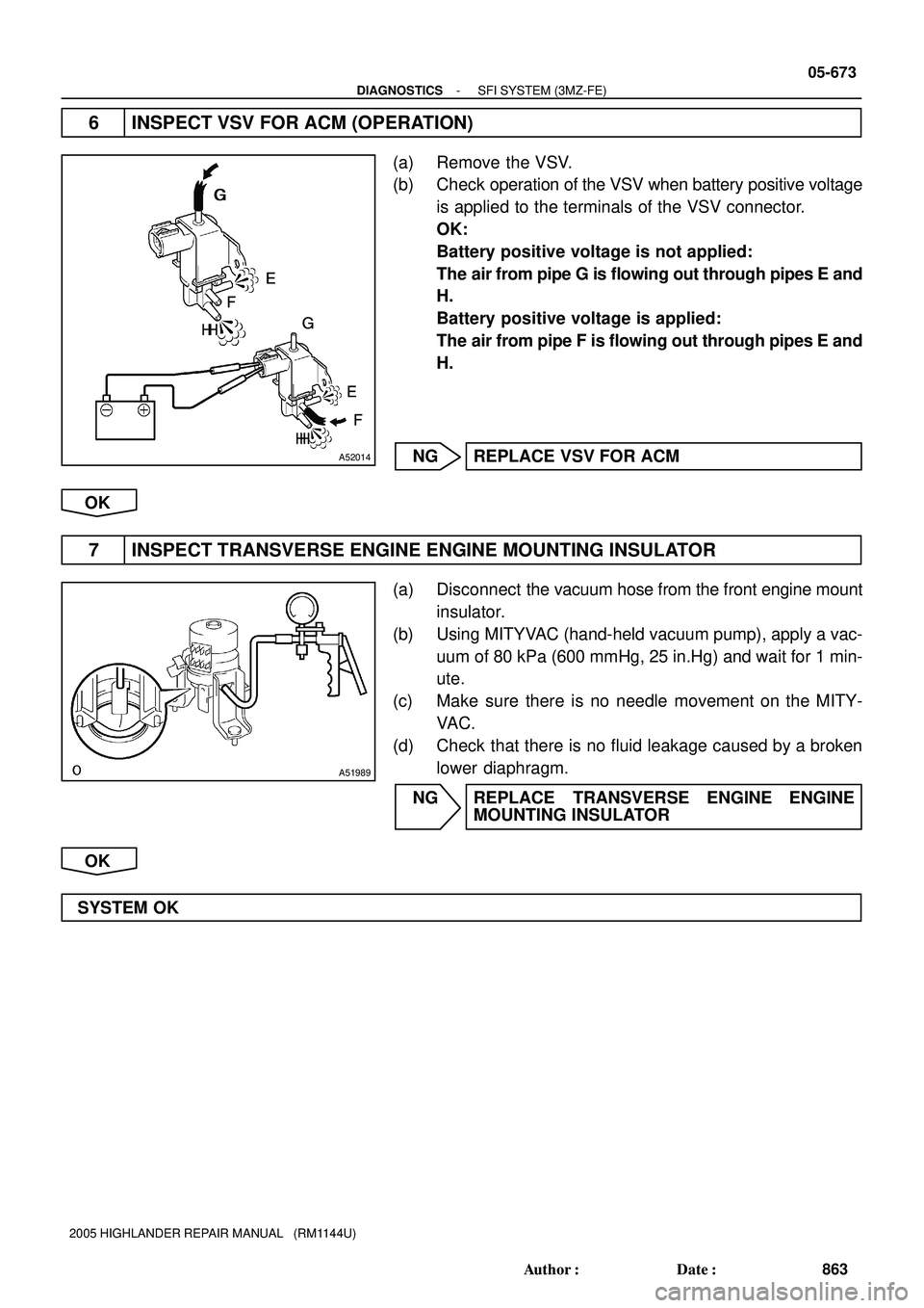
6 INSPECT VSV FOR ACM (OPERATION)
(a) Remove the VSV.
(b) Check operation of the VSV when battery positive voltage
is applied to the terminals of the VSV connector.
OK:
Battery positive voltage is not applied:
The air from pipe G is flowing out through pipes E and
H.
Battery positive voltage is applied:
The air from pipe F is flowing out through pipes E and
H.
NG REPLACE VSV FOR ACM
OK
7 INSPECT TRANSVERSE ENGINE ENGINE MOUNTING INSULATOR
(a) Disconnect the vacuum hose from the front engine mount
insulator.
(b) Using MITYVAC (hand-held vacuum pump), apply a vac-
uum of 80 kPa (600 mmHg, 25 in.Hg) and wait for 1 min-
ute.
(c) Make sure there is no needle movement on the MITY-
VAC.
(d) Check that there is no fluid leakage caused by a broken
lower diaphragm.
NG REPLACE TRANSVERSE ENGINE ENGINE
MOUNTING INSULATOR
OK
SYSTEM OK
Page 856 of 2572

A53769
ENG- ENG+
E5
E9
E1 ECM:
F45157
GND
1 V / Division
0.5 ms / Division
Normal Signal Waveform: ENG + terminal
F45158
1 V / Division
0.5 ms / Division
Normal Signal Waveform: ENG- terminal
GND
05-758
- DIAGNOSTICSTIRE PRESSURE WARNING SYSTEM
948 Author�: Date�:
2005 HIGHLANDER REPAIR MANUAL (RM1144U)
3 INSPECT ECM(ENG+, ENG- OUTPUT)
(a) Connect the brake actuator assy S27 connector and ECM
E5 connector.
(b) Remove the ECM with the connectors connected.
(c) Turn the ignition switch to the ON position.
(d) Using an oscilloscope, connect the terminals, as shown
in the chart below.
Tester Connection
E5-24 (ENG+) - E9-1 (E1)
(e) With the engine idling, check the output waveform.
OK:
Signal waveform appears as shown in the illustration.
HINT:
As the vehicle speed increases, the waveform cycle narrows.
(f) Using an oscilloscope, connect the terminals, as shown
in the chart below.
Tester Connection
E5-30 (ENG-) - E9-1 (E1)
(g) With the engine idling, check the output waveform.
OK:
Signal waveform appears as shown in the illustration.
HINT:
As the engine speed increases, the waveform cycle narrows.
NG REPLACE ECM
OK
Page 980 of 2572

(1) Disconnect the connectors of the meter assy, ECM and body EC")
A53766
E7
E8E9 E6E5
05-2068
- DIAGNOSTICSMULTIPLEX COMMUNICATION SYSTEM
2258 Author�: Date�:
2005 HIGHLANDER REPAIR MANUAL (RM1144U)
(1) Disconnect the connectors of the meter assy, ECM and body ECU.
(2) Inspect the continuity between terminals E6-18 (MPX1) of the ECM vehicle's side connector and
B10-6 (MPX1) of the body ECU vehicle's side connector.
Standard:
Symbols (Terminal No.)Specified Condition
MPX1 (E6-18) @ MPX1 (B10-6)
(equipped with 1MZ-FE)Continuity
MPX1 (E6-18) @ MPX1 (B10-6)
(equipped with 2AZ-FE)Continuity
(3) Inspect the continuity between terminals E6-29 (MPX2) of the ECM vehicle's side connector and
C12-9 (MPX+) of the meter assy vehicle's side connector.
Standard:
Symbols (Terminal No.)Specified Condition
MPX2 (E6-29) @ MPX+ (C12-9)
(equipped with 1MZ-FE)Continuity
MPX2 (E6-29) @ MPX+ (C12-9)
(equipped with 2AZ-FE)Continuity
NG REPAIR OR REPLACE HARNESS AND
CONNECTOR
OK
2 CHECK ECM
(a) Inspect the ECM (power source input).
NOTICE:
Do not disconnect the ECM connector. The inspection should be started from the backside of the
connector.
Standard:
Symbols (Terminal No.)In/OutputConditionSpecified Condition
BATT (E5-3) @ Body groundInputConstant9 - 14 V
+B (E5-1) @ Body groundInputEngine stopped, ignition switch ON9 - 14 V
+B2 (E5-2) @ Body groundInputEngine stopped, ignition switch ON9 - 14 V
NG REPAIR OR REPLACE FUSE OR WIRE
HARNESS AND CONNECTOR
OK
Page 1090 of 2572
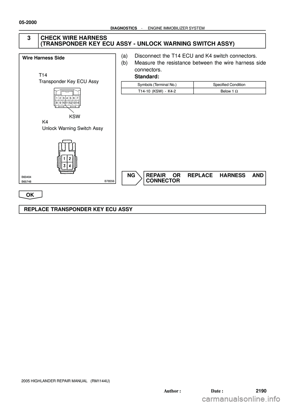
B63404
B65748B78556
T14
Transponder Key ECU Assy
K4
Unlock Warning Switch Assy Wire Harness Side
KSW
05-2000
- DIAGNOSTICSENGINE IMMOBILIZER SYSTEM
2190 Author�: Date�:
2005 HIGHLANDER REPAIR MANUAL (RM1144U)
3 CHECK WIRE HARNESS
(TRANSPONDER KEY ECU ASSY - UNLOCK WARNING SWITCH ASSY)
(a) Disconnect the T14 ECU and K4 switch connectors.
(b) Measure the resistance between the wire harness side
connectors.
Standard:
Symbols (Terminal No.)Specified Condition
T14-10 (KSW) - K4-2Below 1 W
NG REPAIR OR REPLACE HARNESS AND
CONNECTOR
OK
REPLACE TRANSPONDER KEY ECU ASSY
Page 1092 of 2572

B55013B63404B55013B63404B64974
T7
Transponder Key Amplifier Wire Harness Side
T14
Transponder Key ECU Assy
05-2002
- DIAGNOSTICSENGINE IMMOBILIZER SYSTEM
2192 Author�: Date�:
2005 HIGHLANDER REPAIR MANUAL (RM1144U)
INSPECTION PROCEDURE
HINT:
Start the inspection from step 1 when using the hand-held tester and start from step 2 when not using the
hand-held tester.
1 READ VALUE OF HAND-HELD TESTER
(IMMOBILIZER ECU (TRANSPONDER KEY ECU ASSY) (SWITCH CONDITION))
(a) Connect the hand-held tester to the DLC3.
(b) Turn the ignition switch ON with the key that does not start the engine.
(c) Select the item ºANTENNA COILº on the hand-held tester.
OK: ºNORMALº
(Antenna coil is normal) appears on the screen.
ItemMeasurement Item/
Display (Range)Normal ConditionDiagnostic Note
ANTENNA COILAntenna coil condition
/NORMAL or FAILNORMAL: Antenna coil is normal
FAIL: Antenna coil is abnormal-
NG Go to step 2
OK
REPLACE TRANSPONDER KEY ECU ASSY
2 CHECK WIRE HARNESS (TRANSPONDER KEY ECU ASSY - TRANSPONDER KEY
AMPLIFIER) (TRANSPONDER KEY ECU ASSY OR
TRANSPONDER KEY AMPLIFIER - BODY GROUND)
(a) Disconnect the T14 ECU and T7 amplifier connectors.
(b) Measure the resistance of the wire harness side connec-
tors.
Standard:
Tester ConnectionSpecified Condition
T14-8 (VC5) - T7-1 (VC5)Below 1 W
T14-1 1 (CODE) - T7-4 (CODE)Below 1 W
T14-12 (TXCT) - T7-5 (TXCT)Below 1 W
T14-13 (AGND) - T7-7 (GND)Below 1 W
T14-8 (VC5) or T7-1 (VC5) -
Body ground10 kW or higher
T14-1 1 (CODE) or T7-4 (CODE) -
Body ground10 kW or higher
T14-12 (TXCT) or T7-5 (TXCT) -
Body ground10 kW or higher
T14-13 (AGND) or T7-7 (GND) -
Body ground10 kW or higher
NG REPAIR OR REPLACE HARNESS AND
CONNECTOR
OK
REPLACE TRANSPONDER KEY AMPLIFIER
Page 1093 of 2572
- DIAGNOSTICSENGINE IMMOBILIZER SYSTEM
05-2003
2193 Author�: Date�:
2005 HIGHLANDER REPAIR MANUAL (RM1144U)
DTC B2793 TRANSPONDER CHIP MALFUNCTION
CIRCUIT DESCRIPTION
This DTC is output when trouble is found in a key during the key code registration or the key code is not
registered normally. Replace the key when the key code registration is not performed normally and this DTC
is detected.
DTC No.DTC Detection ConditionTrouble Area
B2793Transponder chip malfunction�Key
INSPECTION PROCEDURE
1 CHECK DTC
(a) Delete the DTC.
(b) Insert the key into the ignition key cylinder.
(c) Check that no code is output.
OK NO PROBLEM
NG
2 RE-REGISTER KEY
(a) Delete the DTC.
(b) Re-register the key, and check that the engine starts with the key.
OK NORMAL
NG
REPLACE KEY
052IH-1 1