Page 3141 of 3833

BL-89
C
D
E
F
G
H
J
K
L
MA
B
BL
Trouble DiagnosesEIS001RX
SYMPTOM MATRIX CHART 1
Self-diagnosis related item
*: When NATS detects trouble, the security indicator light")
NATS (NISSAN ANTI-THEFT SYSTEM)
BL-89
C
D
E
F
G
H
J
K
L
MA
B
BL
Trouble DiagnosesEIS001RX
SYMPTOM MATRIX CHART 1
Self-diagnosis related item
*: When NATS detects trouble, the security indicator lights up while ignition key is in the “ON” position. SYMPTOMDisplayed “SELF-DIAG
RESULTS” on CON-
SULT-II screen.DIAGNOSTIC PROCE-
DURE
(Reference page)SYSTEM
(Malfunctioning part or
mode)REFERENCE PART NO.
OF ILLUSTRATION ON
SYSTEM DIAGRAM
●Security indicator
lighting up*
●Engine cannot be
startedECM INT CIRC-IMMUPROCEDURE 1
(BL-91
)ECM B
CHAIN OF ECM-IMMUPROCEDURE 2
(BL-91
)In rare case, “CHAIN OF
ECM-IMMU” might be
stored during key regis-
tration procedure, even if
the system is not mal-
functioning.—
Open circuit in battery
voltage line of IMMU cir-
cuitC1
Open circuit in ignition
line of IMMU circuitC2
Open circuit in ground
line of IMMU circuitC3
Open circuit in communi-
cation line between
IMMU and ECMC4
Short circuit between
IMMU and ECM commu-
nication line and battery
voltage lineC4
Short circuit between
IMMU and ECM commu-
nication line and ground
lineC4
ECM B
IMMU A
DIFFERENCE OF KEYPROCEDURE 3
(BL-94
)Unregistered key D
IMMU A
CHAIN OF IMMU-KEYPROCEDURE 4
(BL-95
)Malfunction of key ID
chipE
IMMU A
Open circuit in ground
line of dongle unit circuitC6
Open or short circuit in
line between IMMU and
dongle unitC5
Dongle unit G
ID DISCORD, IMM-ECMPROCEDURE 5
(BL-96
)System initialization has
not yet been completed.F
ECM B
LOCK MODEPROCEDURE 7
(BL-98
)LOCK MODE D
●MIL staying ON
●Security indicator
lighting up*DON'T ERASE
BEFORE CHECKING
ENG DIAGWORK FLOW
(BL-88 )Engine trouble data and
NATS trouble data have
been detected in ECM—
Page 3142 of 3833

*: When the vehicle is equipped with a dongle unit (RHD models), the security indicator blinks 6 times just after the ignition switch is
turn")
BL-90
NATS (NISSAN ANTI-THEFT SYSTEM)
*: When the vehicle is equipped with a dongle unit (RHD models), the security indicator blinks 6 times just after the ignition switch is
turned to ON. Then the security indicator lights up while the ignition key is in the “ON” position.
SYMPTOM MATRIX CHART 2
Non self-diagnosis related item
DIAGNOSTIC SYSTEM DIAGRAM
SYMPTOMDIAGNOSTIC PROCEDURE
(Reference page)SYSTEM
(Malfunctioning part or mode)REFERENCE PART NO. OF
ILLUSTRATION ON SYSTEM
DIAGRAM
Security Ind. does not light up.PROCEDURE 6
(BL-97
)Security Ind. —
Open circuit between Fuse and
IMMU—
Continuation of initialization
mode—
IMMU A
Security Ind. does not blink just
after initialization even if the
vehicle is equipped with don-
gle unit.
PROCEDURE 8
(BL-99
)NATS might be initialized with-
out connecting dongle unit
properly.—
Open circuit in ground line of
dongle unit circuitC6
Security Ind. does not blink just
after ignition switch is turned to
ON when some malfunction
related to NATS is detected
even if the vehicle is equipped
with dongle unit.Open or short circuit in commu-
nication line between IMMU
and dongle unitC5
Dongle unit G
SEL028X
Page 3153 of 3833

GW-1
GLASSES, WINDOW SYSTEM & MIRRORS
I BODY
CONTENTS
C
D
E
F
G
H
J
K
L
M
SECTION
A
B
GW
GLASSES, WINDOW SYSTEM & MIRRORS
PRECAUTIONS .......................................................... 3
Precautions for Supplemental Restraint System
(SRS) “AIR BAG” and “SEAT BELT PRE-TEN-
SIONER” .................................................................. 3
Precautions .............................................................. 3
WINDSHIELD GLASS AND MOLDING ..................... 4
Removal and Installation .......................................... 4
REMOVAL ............................................................. 4
INSTALLATION ..................................................... 5
SIDE WINDOW GLASS .............................................. 6
Removal and Installation .......................................... 6
REMOVAL ............................................................. 6
INSTALLATION ..................................................... 7
REPAIRING WATER LEAKS FOR WINDSHIELD
..... 7
BACK DOOR WINDOW GLASS ................................ 8
Removal and Installation .......................................... 8
REMOVAL ............................................................. 8
INSTALLATION ..................................................... 9
REAR WINDOW DEFOGGER .................................. 10
Component Parts and Harness Connector Location ... 10
System Description ................................................ 10
Wiring Diagram - DEF - LHD models ..................... 12
Terminals and Reference Value for Time Control
Unit (LHD models) .................................................. 14
Wiring Diagram - DEF - RHD models .................... 15
Terminals and Reference Value for Time Control
Unit (RHD models) .............................................. ... 17
Trouble Diagnoses ................................................. 17
DIAGNOSTIC PROCEDURE SUBTITLE
(SYMPTOM: REAR WINDOW DEFOGGER
DOES NOT ACTIVATE, OR DOES NOT GO OFF
AFTER ACTIVATING.) ........................................ 17
Electrical Components Inspection .......................... 20
REAR WINDOW DEFOGGER RELAY (WITH
DOOR MIRROR DEFOGGER) ........................... 20
REAR WINDOW DEFOGGER RELAY (WITH-OUT DOOR MIRROR DEFOGGER) ................... 20
REAR WINDOW DEFOGGER SWITCH ............. 20
FILAMENT CHECK ............................................. 20
FILAMENT REPAIR ............................................. 21
POWER WINDOW SYSTEM .................................... 23
Component Parts and Harness Connector Location ... 23
System Description ................................................. 23
MANUAL OPERATION ........................................ 24
AUTO OPERATION ............................................. 25
POWER WINDOW LOCK ................................... 25
TIMER FUNCTION .............................................. 25
DRIVER WINDOW ANTI–PINCH FUNCTION .... 25
Schematic (LHD models) ........................................ 26
Wiring Diagram – WINDOW – (LHD models) ......... 27
Terminal and Reference Value for Power Window
Main Switch (LHD models) ..................................... 31
Terminal and Reference Value for Each Door's
Power Window Switch (LHD models) ..................... 32
Schematic (RHD models) ....................................... 33
Wiring Diagram – WINDOW – (RHD models) ........ 34
Terminal and Reference Value for Power Window
Main Switch (RHD models) .................................... 38
Terminal and Reference Value for Each Door's
Power Window Switch (RHD models) .................... 39
Trouble Diagnoses ................................................. 40
Encoder and Limit Switch Check ............................ 41
FRONT DOOR GLASS AND REGULATOR ............. 44
Removal and Installation ........................................ 44
INSTALLATION ................................................... 45
INSPECTION AFTER REMOVAL ....................... 45
INSPECTION AFTER INSTALLATION ................ 45
FITTING INSPECTION ....................................... 45
REAR DOOR GLASS AND REGULATOR ............... 46
Removal and Installation ........................................ 46
INSTALLATION ................................................... 48
INSPECTION AFTER REMOVAL ....................... 48
FITTING INSPECTION ....................................... 48
DOOR MIRROR ........................................................ 49
Precautions to Handle Retractable Power Door Mir-
rors ......................................................................... 49
Page 3154 of 3833
GW-2
Wiring Diagram - MIRROR - LHD models .............. 50
Wiring Diagram - MIRROR - RHD models .............. 52
Removal and Installation ........................................ 54
REMOVAL ........................................................... 54INSTALLATION .................................................... 54
Disassembly and Assembly .................................... 55
DISASSEMBLY .................................................... 55
ASSEMBLY .......................................................... 56
Page 3164 of 3833
GW-12
REAR WINDOW DEFOGGER
Wiring Diagram - DEF - LHD models
EIS0045N
TIWA0028E
Page 3167 of 3833
REAR WINDOW DEFOGGER
GW-15
C
D
E
F
G
H
J
K
L
MA
B
GW
Wiring Diagram - DEF - RHD modelsEIS0045P
TIWA0030E
Page 3179 of 3833
POWER WINDOW SYSTEM
GW-27
C
D
E
F
G
H
J
K
L
MA
B
GW
Wiring Diagram – WINDOW – (LHD models)EIS0045Y
TIWA0033E
Page 3186 of 3833
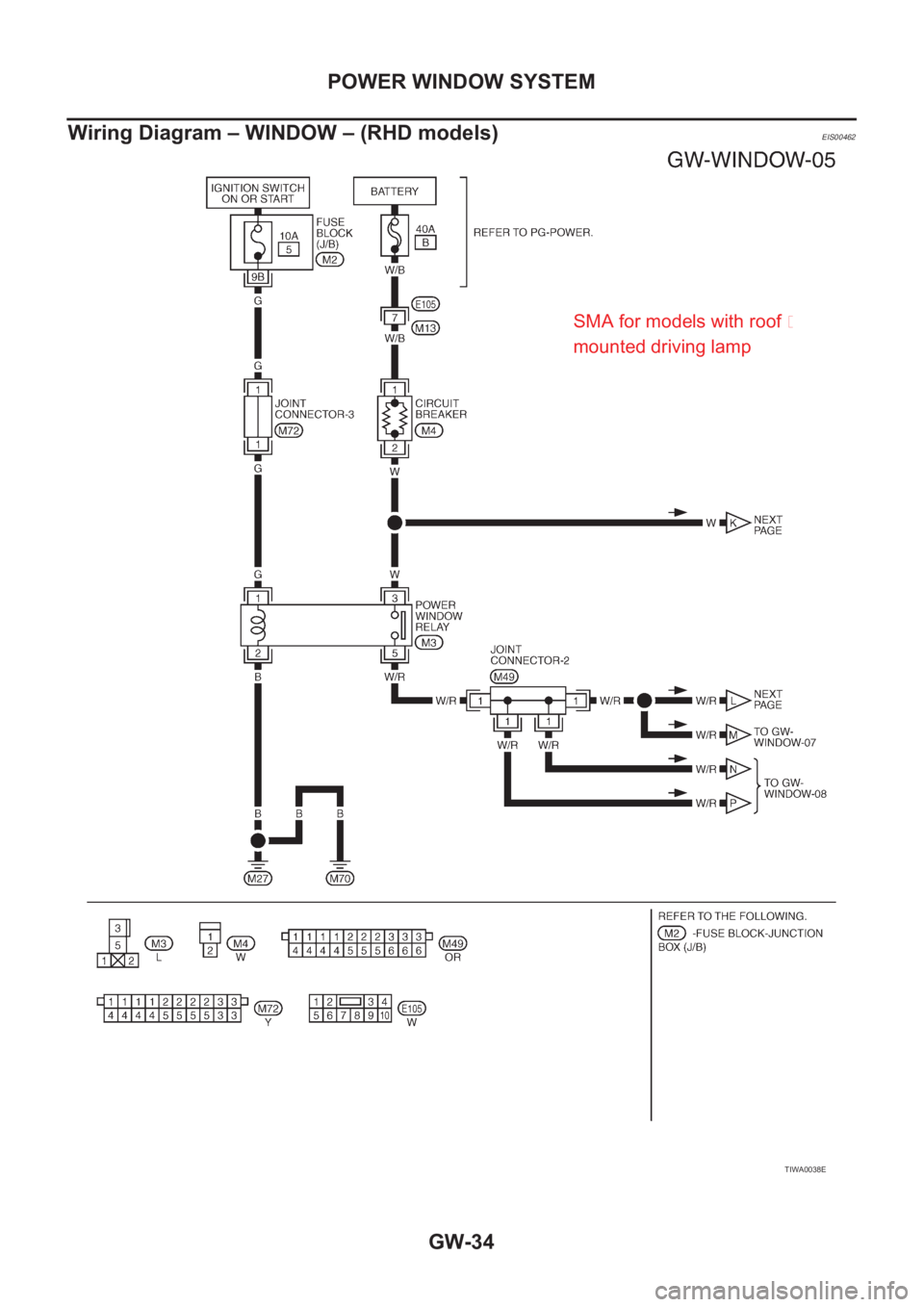
GW-34
POWER WINDOW SYSTEM
Wiring Diagram – WINDOW – (RHD models)
EIS00462
TIWA0038E
SMA for models with roof �
mounted driving lamp


EIS0045Y
TIWA0033E")