2001 NISSAN X-TRAIL diagram
[x] Cancel search: diagramPage 3278 of 3833
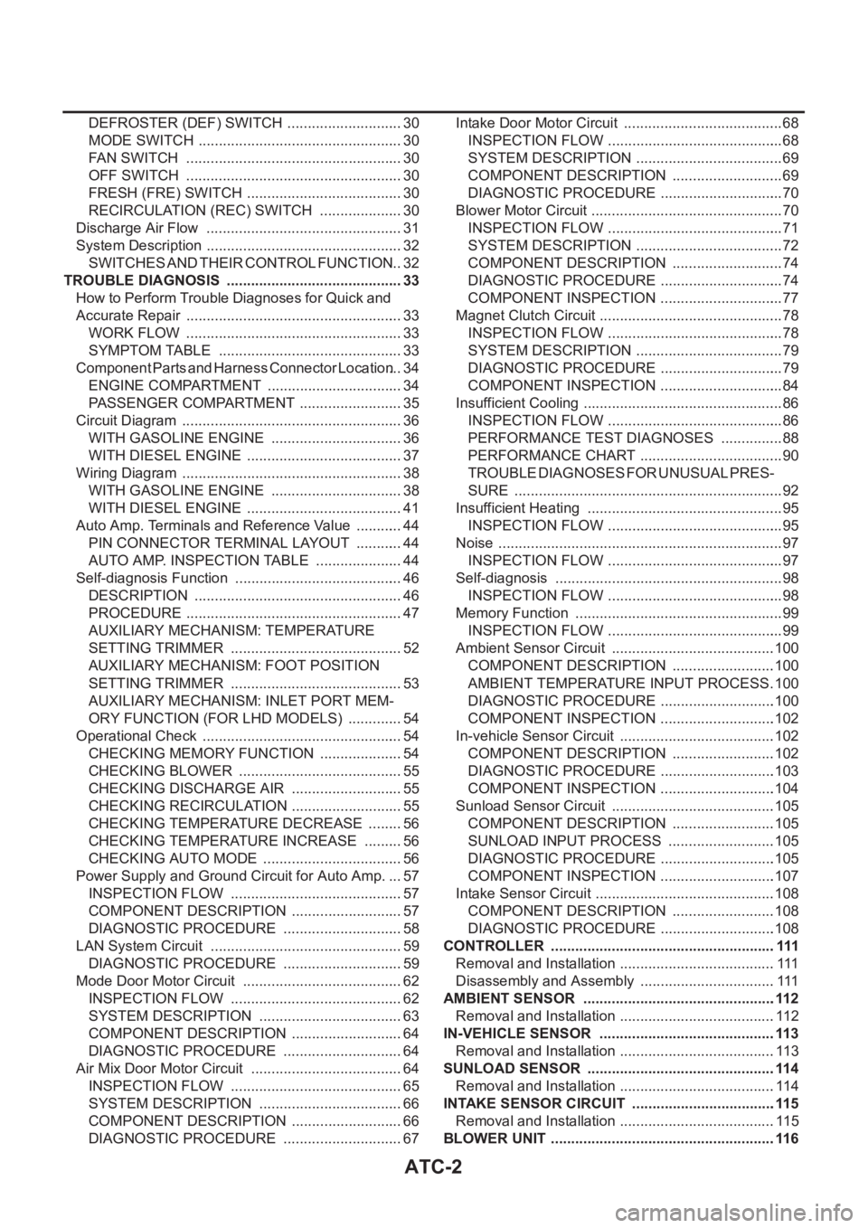
ATC-2
DEFROSTER (DEF) SWITCH ............................. 30
MODE SWITCH ................................................... 30
FAN SWITCH ...................................................... 30
OFF SWITCH ...................................................... 30
FRESH (FRE) SWITCH ....................................... 30
RECIRCULATION (REC) SWITCH ..................... 30
Discharge Air Flow ................................................. 31
System Description ................................................. 32
SWITCHES AND THEIR CONTROL FUNCTION ... 32
TROUBLE DIAGNOSIS ............................................ 33
How to Perform Trouble Diagnoses for Quick and
Accurate Repair ...................................................... 33
WORK FLOW ...................................................... 33
SYMPTOM TABLE .............................................. 33
Component Parts and Harness Connector Location ... 34
ENGINE COMPARTMENT .................................. 34
PASSENGER COMPARTMENT .......................... 35
Circuit Diagram ....................................................... 36
WITH GASOLINE ENGINE ................................. 36
WITH DIESEL ENGINE ....................................... 37
Wiring Diagram ....................................................... 38
WITH GASOLINE ENGINE ................................. 38
WITH DIESEL ENGINE ....................................... 41
Auto Amp. Terminals and Reference Value ............ 44
PIN CONNECTOR TERMINAL LAYOUT ............ 44
AUTO AMP. INSPECTION TABLE ...................... 44
Self-diagnosis Function .......................................... 46
DESCRIPTION .................................................... 46
PROCEDURE ...................................................... 47
AUXILIARY MECHANISM: TEMPERATURE
SETTING TRIMMER ........................................... 52
AUXILIARY MECHANISM: FOOT POSITION
SETTING TRIMMER ........................................... 53
AUXILIARY MECHANISM: INLET PORT MEM-
ORY FUNCTION (FOR LHD MODELS) .............. 54
Operational Check .................................................. 54
CHECKING MEMORY FUNCTION ..................... 54
CHECKING BLOWER ......................................... 55
CHECKING DISCHARGE AIR ............................ 55
CHECKING RECIRCULATION ............................ 55
CHECKING TEMPERATURE DECREASE ......... 56
CHECKING TEMPERATURE INCREASE .......... 56
CHECKING AUTO MODE ................................... 56
Power Supply and Ground Circuit for Auto Amp. ... 57
INSPECTION FLOW ........................................... 57
COMPONENT DESCRIPTION ............................ 57
DIAGNOSTIC PROCEDURE .............................. 58
LAN System Circuit ............................................. ... 59
DIAGNOSTIC PROCEDURE .............................. 59
Mode Door Motor Circuit ........................................ 62
INSPECTION FLOW ........................................
... 62
SYSTEM DESCRIPTION .................................... 63
COMPONENT DESCRIPTION ............................ 64
DIAGNOSTIC PROCEDURE .............................. 64
Air Mix Door Motor Circuit ...................................... 64
INSPECTION FLOW ........................................... 65
SYSTEM DESCRIPTION .................................... 66
COMPONENT DESCRIPTION ............................ 66
DIAGNOSTIC PROCEDURE .............................. 67Intake Door Motor Circuit ........................................ 68
INSPECTION FLOW ............................................ 68
SYSTEM DESCRIPTION ..................................... 69
COMPONENT DESCRIPTION ............................ 69
DIAGNOSTIC PROCEDURE ............................... 70
Blower Motor Circuit ................................................ 70
INSPECTION FLOW ............................................ 71
SYSTEM DESCRIPTION ..................................... 72
COMPONENT DESCRIPTION ............................ 74
DIAGNOSTIC PROCEDURE ............................... 74
COMPONENT INSPECTION ............................... 77
Magnet Clutch Circuit .............................................. 78
INSPECTION FLOW ............................................ 78
SYSTEM DESCRIPTION ..................................... 79
DIAGNOSTIC PROCEDURE ............................... 79
COMPONENT INSPECTION ............................... 84
Insufficient Cooling .................................................. 86
INSPECTION FLOW ............................................ 86
PERFORMANCE TEST DIAGNOSES ................ 88
PERFORMANCE CHART .................................... 90
TROUBLE DIAGNOSES FOR UNUSUAL PRES-
SURE ................................................................... 92
Insufficient Heating ................................................. 95
INSPECTION FLOW ............................................ 95
Noise ....................................................................... 97
INSPECTION FLOW ............................................ 97
Self-diagnosis ......................................................... 98
INSPECTION FLOW ............................................ 98
Memory Function .................................................... 99
INSPECTION FLOW ............................................ 99
Ambient Sensor Circuit .........................................100
COMPONENT DESCRIPTION ..........................100
AMBIENT TEMPERATURE INPUT PROCESS .100
DIAGNOSTIC PROCEDURE .............................100
COMPONENT INSPECTION .............................102
In-vehicle Sensor Circuit .......................................102
COMPONENT DESCRIPTION ..........................102
DIAGNOSTIC PROCEDURE .............................103
COMPONENT INSPECTION .............................104
Sunload Sensor Circuit .........................................105
COMPONENT DESCRIPTION ..........................105
SUNLOAD INPUT PROCESS ...........................105
DIAGNOSTIC PROCEDURE .............................105
COMPONENT INSPECTION .............................107
Intake Sensor Circuit .............................................108
COMPONENT DESCRIPTION ..........................108
DIAGNOSTIC PROCEDURE .............................108
CONTROLLER ........................................................ 111
Removal and Installation .......................................111
Disassembly and Assembly ..................................111
AMBIENT SENSOR ................................................112
Removal and Installation .......................................112
IN-VEHICLE SENSOR ............................................113
Removal and Installation .......................................113
SUNLOAD SENSOR ...............................................114
Removal and Installation .......................................114
INTAKE SENSOR CIRCUIT ....................................115
Removal and Installation .......................................115
BLOWER UNIT ........................................................116
Page 3289 of 3833
PRECAUTIONS
ATC-13
C
D
E
F
G
H
I
K
L
MA
B
AT C
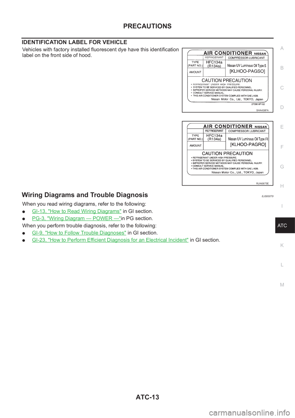
IDENTIFICATION LABEL FOR VEHICLE
Vehicles with factory installed fluorescent dye have this identification
label on the front side of hood.
Wiring Diagrams and Trouble DiagnosisEJS000T9
When you read wiring diagrams, refer to the following:
●GI-13, "How to Read Wiring Diagrams" in GI section.
●PG-3, "Wiring Diagram — POWER —"in PG section.
When you perform trouble diagnosis, refer to the following:
●GI-9, "How to Follow Trouble Diagnoses" in GI section.
●GI-23, "How to Perform Efficient Diagnosis for an Electrical Incident" in GI section.
SHA436FA
RJIA0675E
Page 3303 of 3833
AIR CONDITIONER CONTROL
ATC-27
C
D
E
F
G
H
I
K
L
MA
B
AT C
AIR CONDITIONER CONTROLPFP:27500
Overview Air Conditioner LAN Control SystemEJS000TI
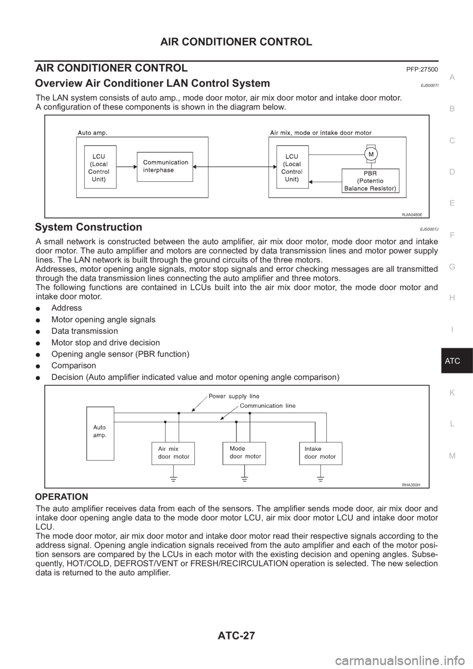
The LAN system consists of auto amp., mode door motor, air mix door motor and intake door motor.
A configuration of these components is shown in the diagram below.
System ConstructionEJS000TJ
A small network is constructed between the auto amplifier, air mix door motor, mode door motor and intake
door motor. The auto amplifier and motors are connected by data transmission lines and motor power supply
lines. The LAN network is built through the ground circuits of the three motors.
Addresses, motor opening angle signals, motor stop signals and error checking messages are all transmitted
through the data transmission lines connecting the auto amplifier and three motors.
The following functions are contained in LCUs built into the air mix door motor, the mode door motor and
intake door motor.
●Address
●Motor opening angle signals
●Data transmission
●Motor stop and drive decision
●Opening angle sensor (PBR function)
●Comparison
●Decision (Auto amplifier indicated value and motor opening angle comparison)
OPERATION
The auto amplifier receives data from each of the sensors. The amplifier sends mode door, air mix door and
intake door opening angle data to the mode door motor LCU, air mix door motor LCU and intake door motor
LCU.
The mode door motor, air mix door motor and intake door motor read their respective signals according to the
address signal. Opening angle indication signals received from the auto amplifier and each of the motor posi-
tion sensors are compared by the LCUs in each motor with the existing decision and opening angles. Subse-
quently, HOT/COLD, DEFROST/VENT or FRESH/RECIRCULATION operation is selected. The new selection
data is returned to the auto amplifier.
RJIA0480E
RHA350H
Page 3305 of 3833
AIR CONDITIONER CONTROL
ATC-29
C
D
E
F
G
H
I
K
L
MA
B
AT C
FAN SPEED CONTROL
Blower speed is automatically controlled based on temperature setting, ambient temperature, in-vehicle tem-
perature, intake temperature, amount of sunload and air mix door position.
With FAN switch set to AUTO, the blower motor starts to gradually increase air flow volume.
When engine coolant temperature is low, the blower motor operation is delayed to prevent cool air from flow-
ing.
INTAKE DOOR CONTROL
The intake doors are automatically controlled by: The temperature setting, ambient temperature, in-vehicle
temperature, intake temperature, amount of sunload and ON-OFF operation of the compressor.
OUTLET DOOR CONTROL
The outlet door is automatically controlled by: The temperature setting, ambient temperature, in-vehicle tem-
perature, intake temperature and amount of sunload.
MAGNET CLUTCH CONTROL
The ECM controls compressor operation using input signals from the throttle position sensor and auto ampli-
fier.
SELF-DIAGNOSTIC SYSTEM
The self-diagnostic system is built into the auto amplifier (LCU) to quickly locate the cause of malfunctions.
Overview of Control systemEJS000TK
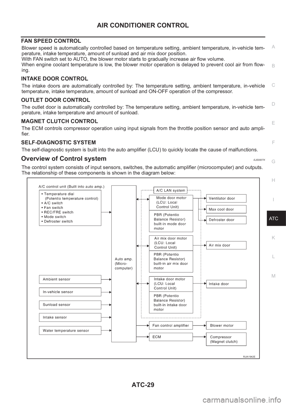
The control system consists of input sensors, switches, the automatic amplifier (microcomputer) and outputs.
The relationship of these components is shown in the diagram below:
RJIA1942E
Page 3312 of 3833
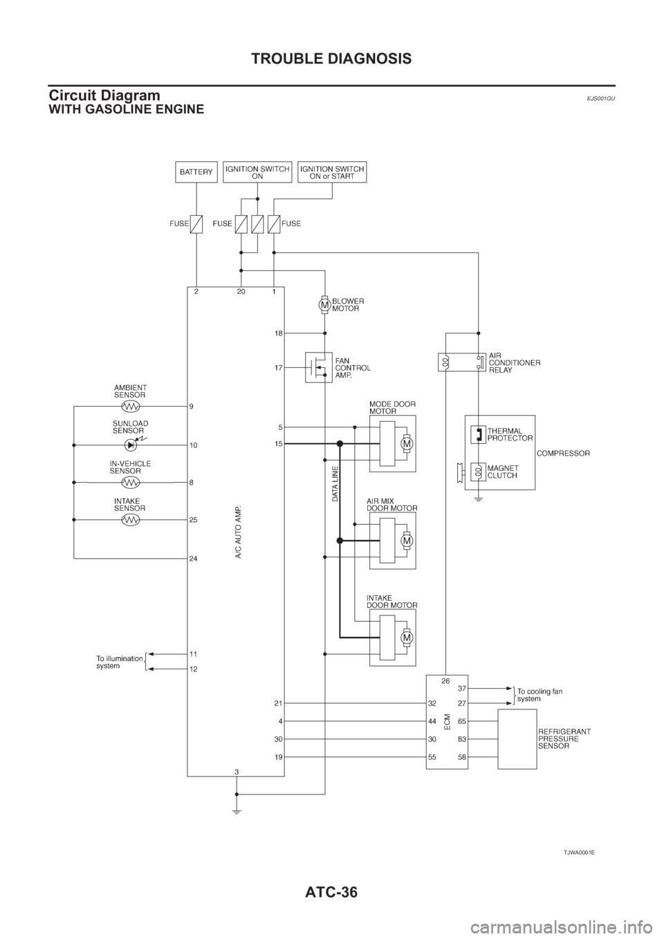
ATC-36
TROUBLE DIAGNOSIS
Circuit Diagram
EJS001GU
WITH GASOLINE ENGINE
TJWA0001E
Page 3314 of 3833
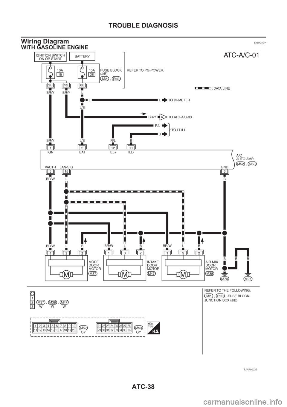
ATC-38
TROUBLE DIAGNOSIS
Wiring Diagram
EJS001GV
WITH GASOLINE ENGINE
TJWA0002E
Page 3427 of 3833
MTC-1
MANUAL AIR CONDITIONER
J AIR CONDITIONER
CONTENTS
C
D
E
F
G
H
I
K
L
M
SECTION
A
B
MTC
MANUAL AIR CONDITIONER
PRECAUTIONS .......................................................... 2
Precautions for Supplemental Restraint System
(SRS) “AIR BAG” and “SEAT BELT PRE-TEN-
SIONER” .................................................................. 2
Wiring Diagrams and Trouble Diagnosis .................. 2
TROUBLE DIAGNOSIS .............................................. 3
How to Perform Trouble Diagnoses for Quick and
Accurate Repair ....................................................... 3
WORK FLOW ........................................................ 3
SYMPTOM TABLE ................................................ 3
Component Parts and Harness Connector Location ..... 4
PASSENGER COMPARTMENT ........................... 4
Discharge Air Flow ................................................... 5
Wiring Diagram-HEATER ......................................... 6
Operational Check ................................................... 7
CHECKING BLOWER ........................................... 7
CHECKING DISCHARGE AIR .............................. 7
CHECKING RECIRCULATION ............................. 7
CHECKING TEMPERATURE DECREASE .......... 8
CHECKING TEMPERATURE INCREASE ............ 8
Mode Door ............................................................... 9
Air Mix Door ........................................................... 10
Intake Door Motor Circuit ........................................ 11
INSPECTION FLOW ............................................ 11
COMPONENT DESCRIPTION ............................ 11
DIAGNOSTIC PROCEDURE .............................. 12
Blower Motor Circuit ............................................... 14
INSPECTION FLOW ........................................... 14
DIAGNOSTIC PROCEDURE .............................. 15
COMPONENT INSPECTION .............................. 17
Insufficient Heating ................................................. 18
INSPECTION FLOW ........................................... 18CONTROLLER .......................................................... 20
Removal and Installation ........................................ 20
Disassembly and Assembly .................................... 20
BLOWER MOTOR .................................................... 21
Removal and Installation ........................................ 21
BLOWER FAN RESISTOR ....................................... 22
Removal and Installation ........................................ 22
INTAKE DOOR MOTOR ........................................... 23
Removal and Installation ........................................ 23
HEATER UNIT ........................................................... 24
Removal and Installation ........................................ 24
REMOVAL ........................................................... 24
INSTALLATION ................................................... 25
Disassembly and Assembly .................................... 25
HEATER CORE ......................................................
... 26
Removal and Installation ........................................ 26
MODE DOOR ............................................................ 27
Control Linkage adjustment .................................... 27
MODE DOOR CONTROL CABLE ....................... 27
AIR MIX DOOR ......................................................... 28
Control Linkage Adjustment ................................... 28
AIR MIX DOOR CONTROL CABLE .................... 28
DUCTS AND GRILLES ............................................. 29
Removal and Installation ........................................ 29
VENTILATOR DUCT, DEFROSTER NOZZLE
AND DEFROSTER DUCTS ................................ 29
CENTER VENTILATOR GRILLE ......................... 29
SIDE VENTILATOR GRILLE ............................... 29
FOOT DUCT ....................................................... 30
FLOOR DUCT ..................................................... 30
Page 3428 of 3833
MTC-2
PRECAUTIONS
PRECAUTIONS
PFP:00001
Precautions for Supplemental Restraint System (SRS) “AIR BAG” and “SEAT
BELT PRE-TENSIONER”
EJS0028D
The Supplemental Restraint System such as “AIR BAG” and “SEAT BELT PRE-TENSIONER”, used along
with a front seat belt, helps to reduce the risk or severity of injury to the driver and front passenger for certain
types of collision. Information necessary to service the system safely is included in the SRS and SB section of
this Service Manual.
WARNING:
●To avoid rendering the SRS inoperative, which could increase the risk of personal injury or death
in the event of a collision which would result in air bag inflation, all maintenance must be per-
formed by an authorized NISSAN/INFINITI dealer.
●Improper maintenance, including incorrect removal and installation of the SRS, can lead to per-
sonal injury caused by unintentional activation of the system. For removal of Spiral Cable and Air
Bag Module, see the SRS section.
●Do not use electrical test equipment on any circuit related to the SRS unless instructed to in this
Service Manual. SRS wiring harnesses can be identified by yellow and/or orange harness connec-
tors.
Wiring Diagrams and Trouble DiagnosisEJS000WA
When you read wiring diagrams, refer to the following:
●GI-13, "How to Read Wiring Diagrams" in GI section.
●PG-3, "Wiring Diagram — POWER —" in EL section.
When you perform trouble diagnosis, refer to the following:
●GI-9, "How to Follow Trouble Diagnoses" in GI section.
●GI-23, "How to Perform Efficient Diagnosis for an Electrical Incident" in GI section.