Page 3555 of 3833
SPOT LAMPS
LT-65
C
D
E
F
G
H
I
J
L
MA
B
LT
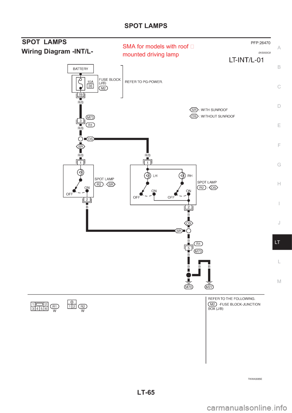
SPOT LAMPSPFP:26470
Wiring Diagram -INT/L-EKS003C8
TKWA0085E
SMA for models with roof �
mounted driving lamp
Page 3559 of 3833

DI-1
DRIVER INFORMATION SYSTEM
K ELECTRICAL
CONTENTS
C
D
E
F
G
H
I
J
L
M
SECTION
A
B
DI
DRIVER INFORMATION SYSTEM
PRECAUTIONS .......................................................... 3
Precautions for Supplemental Restraint System
(SRS) “AIR BAG” and “SEAT BELT PRE-TEN-
SIONER” .................................................................. 3
Wiring Diagrams and Trouble Diagnosis .................. 3
COMBINATION METERS (LHD MODELS) ................ 4
System Description .................................................. 4
UNIFIED CONTROL METER ................................ 4
HOW TO CHANGE THE DISPLAY FOR ODO/
TRIP METER ........................................................ 4
POWER SUPPLY AND GROUND CIRCUIT ........ 4
WATER TEMPERATURE GAUGE ........................ 4
TACHOMETER ..................................................... 5
FUEL GAUGE ....................................................... 5
SPEEDOMETER ................................................... 5
Component Parts and Harness Connector Location ..... 5
Combination Meter ................................................... 6
CHECK .................................................................. 6
Schematic ................................................................ 7
Wiring Diagram — METER — .................................. 8
Meter/Gauge Operation and Odo/Trip Meter Seg-
ment Check in Diagnosis Mode ............................. 10
DIAGNOSIS FUNCTION ..................................... 10
HOW TO ALTERNATE DIAGNOSIS MODE ....... 10
Trouble Diagnoses .................................................. 11
PRELIMINARY CHECK ....................................... 11
SYMPTOM CHART ............................................. 12
Power Supply and Ground Circuit Check ............... 13
Inspection/Engine Speed Signal ............................ 13
Inspection/Water Temperature Gauge /Gasoline
Engine Models ....................................................... 14
Inspection/Water Temperature Gauge (Diesel
Engine Models) ...................................................... 15
Inspection/Vehicle speed signal ............................. 16
Inspection/Fuel Level Sensor Unit ......................... 17
FUEL LEVEL SENSOR UNIT ............................. 17
LOW-FUEL WARNING LAMP ............................. 17
The Fuel Gauge Pointer Fluctuates·Indicator
Wrong Value·or Varies. ........................................... 18
The Fuel Gauge Does Not Move to Full-position. ... 19The Fuel Gauge Does Not Work. ........................... 19
Low Fuel Warning Lamp Illuminate or Not Illuminate ... 20
Electrical Components Inspection .......................... 21
FUEL LEVEL SENSOR UNIT CHECK / GASO-
LINE ENGINE MODELS ..................................... 21
FUEL LEVEL SENSOR UNIT CHECK / DIESEL
ENGINE MODELS EXCEPT FOR NORTHERN
EUROPE ............................................................. 21
FUEL LEVEL SENSOR UNIT CHECK / DIESEL
ENGINE MODELS FOR NORTHERN EUROPE ... 22
THERMAL TRANSMITTER CHECK ................... 22
Removal and Installation for Combination Meter .... 23
Disassembly and Assembly for Combination Meter ... 23
COMBINATION METERS (RHD MODELS) .............. 24
System Description ................................................. 24
UNIFIED CONTROL METER ...........................
... 24
HOW TO CHANGE THE DISPLAY FOR ODO/
TRIP METER ....................................................... 24
POWER SUPPLY AND GROUND CIRCUIT ....... 24
WATER TEMPERATURE GAUGE ...................... 24
TACHOMETER .................................................... 25
FUEL GAUGE ..................................................... 25
SPEEDOMETER ................................................. 25
Component Parts and Harness Connector Location ... 25
Combination Meter .............................................. ... 26
CHECK ................................................................ 26
Schematic ............................................................... 27
Wiring Diagram — METER — ................................ 28
Meter/Gauge Operation and Odo/Trip Meter Seg-
ment Check in Diagnosis Mode .............................. 30
DIAGNOSIS FUNCTION ..................................... 30
HOW TO ALTERNATE DIAGNOSIS MODE ....... 30
Trouble Diagnoses ................................................. 30
PRELIMINARY CHECK ....................................... 30
SYMPTOM CHART ............................................. 32
Power Supply and Ground Circuit Check ............... 32
Inspection/Engine Speed Signal ............................. 33
Inspection/Water Temperature Gauge/Gasoline
Engine Models ........................................................ 33
Inspection/Water Temperature Gauge/Diesel
Page 3560 of 3833

DI-2
Engine Models ........................................................ 35
Inspection/Vehicle speed signal ............................. 35
Inspection/Fuel Level Sensor Unit .......................... 37
FUEL LEVEL SENSOR UNIT .............................. 37
LOW-FUEL WARNING LAMP ............................. 37
The Fuel Gauge Pointer Fluctuates·Indicator
Wrong Value·or Varies. ........................................... 38
The Fuel Gauge Does Not Move to Full-position. ... 39
The Fuel Gauge Does Not Work. ........................... 39
Low Fuel Warning Lamp Illuminate or Not Illuminate ... 40
Electrical Components Inspection .......................... 41
FUEL LEVEL SENSOR UNIT CHECK / GASO-
LINE ENGINE MODELS ...................................... 41
FUEL LEVEL SENSOR UNIT CHECK / DIESEL
ENGINE MODELS ............................................... 41
THERMAL TRANSMITTER CHECK ................... 42
Removal and Installation for Combination Meter .... 42
Disassembly and Assembly for Combination Meter ... 42
WARNING LAMPS .................................................... 43
Schematic ............................................................... 43
Wiring Diagram — WARN —/ LHD Models ............ 44Wiring Diagram — WARN — / RHD Models ........... 50
Electrical Components Inspection ........................... 56
FUEL WARNING LAMP OPERATION CHECK ... 56
OIL PRESSURE SWITCH CHECK ...................... 56
DIODE CHECK .................................................... 56
A/T INDICATOR ......................................................... 57
Wiring Diagram — AT/IND — ................................. 57
WARNING CHIME .................................................. ... 58
System Description ................................................. 58
POWER SUPPLY AND GROUND CIRCUIT ....... 58
IGNITION KEY WARNING CHIME ...................... 58
LIGHT WARNING CHIME ................................... 58
SEAT BELT WARNING CHIME ........................... 58
Wiring Diagram — CHIME — ................................. 59
Symptom Chart ....................................................... 61
Power Supply and Ground Circuit Check ............... 62
Lighting Switch Input Signal Check ......................... 63
Key Switch Insert Signal Check .............................. 65
Door Unlock Sensor Check ..................................... 66
Front Door Switch (driver side) Check .................... 68
CLOCK ...................................................................... 70
Wiring Diagram — CLOCK — ................................. 70
Page 3561 of 3833
 “AIR BAG” and “SEAT
BELT PRE-TENSIONER”
EKS00367
The Supplemental Restra")
PRECAUTIONS
DI-3
C
D
E
F
G
H
I
J
L
MA
B
DI
PRECAUTIONS PFP:00011
Precautions for Supplemental Restraint System (SRS) “AIR BAG” and “SEAT
BELT PRE-TENSIONER”
EKS00367
The Supplemental Restraint System such as “AIR BAG” and “SEAT BELT PRE-TENSIONER”, used along
with a front seat belt, helps to reduce the risk or severity of injury to the driver and front passenger for certain
types of collision. Information necessary to service the system safely is included in the SRS and SB section of
this Service Manual.
WARNING:
●To avoid rendering the SRS inoperative, which could increase the risk of personal injury or death
in the event of a collision which would result in air bag inflation, all maintenance must be per-
formed by an authorized NISSAN/INFINITI dealer.
●Improper maintenance, including incorrect removal and installation of the SRS, can lead to per-
sonal injury caused by unintentional activation of the system. For removal of Spiral Cable and Air
Bag Module, see the SRS section.
●Do not use electrical test equipment on any circuit related to the SRS unless instructed to in this
Service Manual. SRS wiring harnesses can be identified by yellow and/or orange harness connec-
tors.
Wiring Diagrams and Trouble Diagnosis EKS00368
When you read wiring diagrams, refer to the followings:
●Refer to GI-13, "How to Read Wiring Diagrams" in GI section
●Refer to PG-2, "POWER SUPPLY ROUTING" for power distribution circuit in PG section
When you perform trouble diagnosis, refer to the followings:
●Refer to GI-10, "HOW TO FOLLOW TEST GROUPS IN TROUBLE DIAGNOSES" in GI section
●Refer to GI-23, "How to Perform Efficient Diagnosis for an Electrical Incident" in GI section
Page 3566 of 3833
DI-8
COMBINATION METERS (LHD MODELS)
Wiring Diagram — METER —
EKS002ZB
TKWA0086E
Page 3586 of 3833
DI-28
COMBINATION METERS (RHD MODELS)
Wiring Diagram — METER —
EKS0030L
TKWA0088E
Page 3602 of 3833
DI-44
WARNING LAMPS
Wiring Diagram — WARN —/ LHD Models
EKS002HH
TKWA0726E
Page 3608 of 3833
DI-50
WARNING LAMPS
Wiring Diagram — WARN — / RHD Models
EKS0031U
TKWA0727E

Wiring Diagram — METER —
EKS002ZB
TKWA0086E")

Wiring Diagram — METER —
EKS0030L
TKWA0088E")

