Page 3614 of 3833

DI-56
WARNING LAMPS
Electrical Components Inspection
EKS002HK
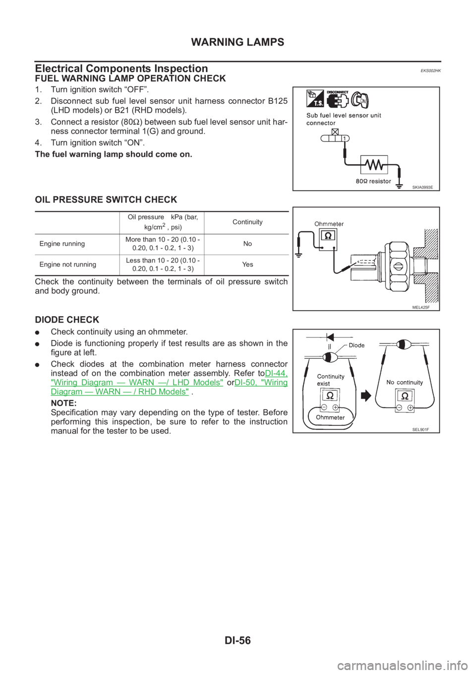
FUEL WARNING LAMP OPERATION CHECK
1. Turn ignition switch “OFF”.
2. Disconnect sub fuel level sensor unit harness connector B125
(LHD models) or B21 (RHD models).
3. Connect a resistor (80Ω) between sub fuel level sensor unit har-
ness connector terminal 1(G) and ground.
4. Turn ignition switch “ON”.
The fuel warning lamp should come on.
OIL PRESSURE SWITCH CHECK
Check the continuity between the terminals of oil pressure switch
and body ground.
DIODE CHECK
●Check continuity using an ohmmeter.
●Diode is functioning properly if test results are as shown in the
figure at left.
●Check diodes at the combination meter harness connector
instead of on the combination meter assembly. Refer toDI-44,
"Wiring Diagram — WARN —/ LHD Models" orDI-50, "Wiring
Diagram — WARN — / RHD Models" .
NOTE:
Specification may vary depending on the type of tester. Before
performing this inspection, be sure to refer to the instruction
manual for the tester to be used.
SKIA0993E
Oil pressure kPa (bar,
kg/cm2 , psi)Continuity
Engine runningMore than 10 - 20 (0.10 -
0.20, 0.1 - 0.2, 1 - 3)No
Engine not runningLess than 10 - 20 (0.10 -
0.20, 0.1 - 0.2, 1 - 3)Ye s
MEL425F
SEL901F
Page 3615 of 3833
A/T INDICATOR
DI-57
C
D
E
F
G
H
I
J
L
MA
B
DI
A/T INDICATORPFP:24814
Wiring Diagram — AT/IND —EKS002HL
TKWA0103E
Page 3617 of 3833
WARNING CHIME
DI-59
C
D
E
F
G
H
I
J
L
MA
B
DI
Wiring Diagram — CHIME —EKS002XJ
TKWA0101E
SMA for models with roof mounted driving lamp
Page 3628 of 3833
DI-70
CLOCK
CLOCK
PFP:25820
Wiring Diagram — CLOCK —EKS002I5
TKWA0129E
Page 3629 of 3833

WW-1
WIPER, WASHER & HORN
K ELECTRICAL
CONTENTS
C
D
E
F
G
H
I
J
L
M
SECTION
A
B
WW
WIPER, WASHER & HORN
PRECAUTIONS .......................................................... 3
Precautions for Supplemental Restraint System
(SRS) “AIR BAG” and “SEAT BELT PRE-TEN-
SIONER” .................................................................. 3
Wiring Diagrams and Trouble Diagnosis .................. 3
FRONT WIPER AND WASHER SYSTEM .................. 4
System Description .................................................. 4
WIPER OPERATION ............................................ 4
WASHER OPERATION ......................................... 4
Wiring Diagram — WIPER — .................................. 6
Terminal and Reference Values for Combination
Switch ....................................................................... 7
Removal and Installation for Front Wiper Arms,
Adjustment for Wiper Arms Stop Location ............... 7
Removal and Installation for Wiper Motor and Link-
age ........................................................................... 8
REMOVAL ............................................................. 9
INSTALLATION ..................................................... 9
Washer Nozzle Adjustment .................................... 10
Washer Tube Layout .............................................. 10
Removal and Installation for Washer Nozzle .......... 11
REMOVAL ............................................................ 11
INSTALLATION .................................................... 11
Inspection for Washer Nozzle ................................. 11
CHECK VALVE .................................................... 11
Removal and Installation for Wiper and Washer
Switch ...................................................................... 11
REMOVAL ............................................................ 11
INSTALLATION .................................................... 11
Removal and Installation for Washer Tank ............. 12
Removal and Installation for Washer Pump ........... 12
REAR WIPER AND WASHER SYSTEM .................. 13
Wiring Diagram — WIP/R — .................................. 13
Terminal and Reference Values for Combination
Switch ..................................................................... 15
Removal and Installation for Rear Wiper Arms ...... 15
WIPER ARMS ..................................................... 15
Removal and Installation for Wiper Motor and Link-
age ......................................................................... 16REMOVAL ........................................................... 16
INSTALLATION ................................................... 16
Washer Nozzle Adjustment .................................... 17
Removal and Installation for Rear Washer Nozzle ... 17
REMOVAL ........................................................... 17
INSTALLATION ................................................... 17
Inspection for Washer Nozzle ................................. 17
CHECK VALVE .................................................... 17
Removal and Installation for Wiper and Washer
Switch ..................................................................... 18
Removal and Installation for Washer Tank ............. 18
Removal and Installation for Washer Pump ........... 18
Washer Tube Layout .............................................. 18
HEADLAMP WASHER ............................................. 19
System Description ................................................. 19
Wiring Diagram –HLC– ........................................... 20
Removal and Installation for Washer Nozzle .......... 21
REMOVAL ........................................................... 21
INSTALLATION ................................................... 21
Inspection for Washer Nozzle ................................. 21
CHECK VALVE .................................................... 21
Removal and Installation for Washer Tank ............. 21
Removal and Installation for Washer Pump ........... 21
Washer Tube Layout .............................................. 22
HORN ........................................................................ 23
Wiring Diagram — HORN — .................................. 23
Removal and Installation ........................................ 24
REMOVAL ........................................................... 24
INSTALLATION ................................................... 24
CIGARETTE LIGHTER ............................................. 25
Wiring Diagram — CIGAR — ................................. 25
Removal and Installation ........................................ 26
REMOVAL ........................................................... 26
INSTALLATION ................................................... 26
POWER SOCKET ..................................................... 27
Wiring Diagram –POWER SOCKET– .................... 27
Removal and Installation for Front Power Socket ... 28
REMOVAL ........................................................... 28
Page 3631 of 3833

PRECAUTIONS
WW-3
C
D
E
F
G
H
I
J
L
MA
B
WW
PRECAUTIONS PFP:00011
Precautions for Supplemental Restraint System (SRS) “AIR BAG” and “SEAT
BELT PRE-TENSIONER”
EKS0079K
The Supplemental Restraint System such as “AIR BAG” and “SEAT BELT PRE-TENSIONER”, used along
with a front seat belt, helps to reduce the risk or severity of injury to the driver and front passenger for certain
types of collision. Information necessary to service the system safely is included in the SRS and SB section of
this Service Manual.
WARNING:
●To avoid rendering the SRS inoperative, which could increase the risk of personal injury or death
in the event of a collision which would result in air bag inflation, all maintenance must be per-
formed by an authorized NISSAN/INFINITI dealer.
●Improper maintenance, including incorrect removal and installation of the SRS, can lead to per-
sonal injury caused by unintentional activation of the system. For removal of Spiral Cable and Air
Bag Module, see the SRS section.
●Do not use electrical test equipment on any circuit related to the SRS unless instructed to in this
Service Manual. SRS wiring harnesses can be identified by yellow and/or orange harness connec-
tors.
Wiring Diagrams and Trouble Diagnosis EKS0079L
When you read wiring diagrams, refer to the followings:
●Refer to GI-13, "How to Read Wiring Diagrams" in GI section
●Refer to PG-2, "POWER SUPPLY ROUTING" for power distribution circuit in PG section
When you perform trouble diagnosis, refer to the followings:
●Refer to GI-10, "HOW TO FOLLOW TEST GROUPS IN TROUBLE DIAGNOSES" in GI section
●Refer to GI-23, "How to Perform Efficient Diagnosis for an Electrical Incident" in GI section
Page 3634 of 3833
WW-6
FRONT WIPER AND WASHER SYSTEM
Wiring Diagram — WIPER —
EKS0032O
TKWA0104E
Page 3641 of 3833
REAR WIPER AND WASHER SYSTEM
WW-13
C
D
E
F
G
H
I
J
L
MA
B
WW
REAR WIPER AND WASHER SYSTEMPFP:28710
Wiring Diagram — WIP/R —EKS0032Z
TKWA0105E