Page 3668 of 3833
LAN-6
[CAN]
CAN SYSTEM (FOR A/T MODELS)
Wiring Diagram — CAN —
EKS002AF
TKWA0728E
Page 3675 of 3833
CAN SYSTEM (FOR M/T MODELS)
LAN-13
[CAN]
C
D
E
F
G
H
I
J
L
MA
B
LAN
Wiring Diagram — CAN —EKS002FM
TKWA0729E
Page 3689 of 3833

AV-1
AUDIO, VISUAL & TELEPHONE SYSTEM
K ELECTRICAL
CONTENTS
C
D
E
F
G
H
I
J
L
M
SECTION
A
B
AV
AUDIO, VISUAL & TELEPHONE SYSTEM
PRECAUTIONS .......................................................... 2
Precautions for Supplemental Restraint System
(SRS) “AIR BAG” and “SEAT BELT PRE-TEN-
SIONER” .................................................................. 2
Wiring Diagrams and Trouble Diagnosis .................. 2
AUDIO ......................................................................... 3
System Description .................................................. 3
NATS AUDIO LINK ............................................... 3
SPEED DEPENDENT VOLUME CONTROL ........ 4
PERSONAL AUDIO SETTINGS ........................... 4
Schematic ................................................................ 5
Wiring Diagram —AUDIO— ..................................... 6
LHD MODELS ....................................................... 6
RHD MODELS ...................................................... 9Trouble Diagnoses ................................................. 12
AUDIO UNIT ..................................................... ... 12
Inspection ............................................................... 13
AUDIO UNIT ..................................................... ... 13
ANTENNA ........................................................ ... 13
Removal and Installation of Audio Unit ................... 13
Locking CD auto-changer mechanism ................... 14
DAMPER LOCK PROCEDURE .......................... 14
Removal and Installation of CD Auto-Changer ....... 14
Removal and Installation of Speakers .................... 15
Removal and Installation of Tweeters ..................... 15
AUDIO ANTENNA .................................................... 16
Antenna Route ........................................................ 16
Removal and Installation of Roof Antenna ............. 16
Page 3690 of 3833
 “AIR BAG” and “SEAT
BELT PRE-TENSIONER”
EKS0036C
The Supplemental Restraint System such as �")
AV-2
PRECAUTIONS
PRECAUTIONS
PFP:00011
Precautions for Supplemental Restraint System (SRS) “AIR BAG” and “SEAT
BELT PRE-TENSIONER”
EKS0036C
The Supplemental Restraint System such as “AIR BAG” and “SEAT BELT PRE-TENSIONER”, used along
with a front seat belt, helps to reduce the risk or severity of injury to the driver and front passenger for certain
types of collision. Information necessary to service the system safely is included in the SRS and SB section of
this Service Manual.
WARNING:
●To avoid rendering the SRS inoperative, which could increase the risk of personal injury or death
in the event of a collision which would result in air bag inflation, all maintenance must be per-
formed by an authorized NISSAN/INFINITI dealer.
●Improper maintenance, including incorrect removal and installation of the SRS, can lead to per-
sonal injury caused by unintentional activation of the system. For removal of Spiral Cable and Air
Bag Module, see the SRS section.
●Do not use electrical test equipment on any circuit related to the SRS unless instructed to in this
Service Manual. SRS wiring harnesses can be identified by yellow and/or orange harness connec-
tors.
Wiring Diagrams and Trouble Diagnosis EKS0036D
When you read wiring diagrams, refer to the followings:
●Refer to GI-13, "How to Read Wiring Diagrams" in GI section
●Refer to PG-2, "POWER SUPPLY ROUTING" for power distribution circuit in PG section
When you perform trouble diagnosis, refer to the followings:
●Refer to GI-10, "HOW TO FOLLOW TEST GROUPS IN TROUBLE DIAGNOSES" in PG section
●Refer to GI-23, "How to Perform Efficient Diagnosis for an Electrical Incident" in PG section
Page 3694 of 3833
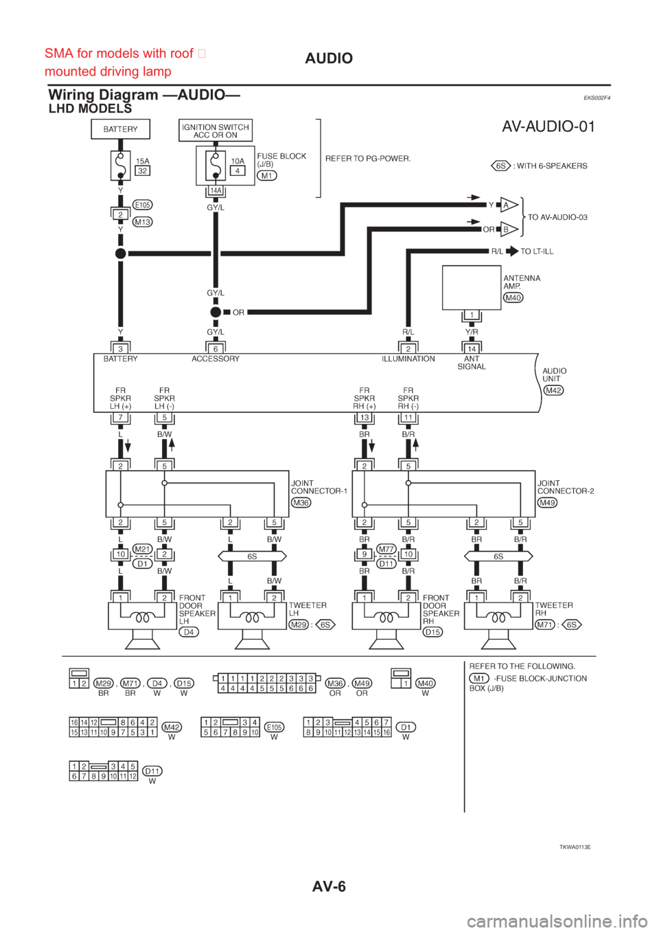
AV-6
AUDIO
Wiring Diagram —AUDIO—
EKS002F4
LHD MODELS
TKWA0113E
SMA for models with roof �
mounted driving lamp
Page 3705 of 3833

PG-1
POWER SUPPLY, GROUND & CIRCUIT ELEMENTS
K ELECTRICAL
CONTENTS
C
D
E
F
G
H
I
J
L
M
SECTION
A
B
PG
POWER SUPPLY, GROUND & CIRCUIT ELEMENTS
POWER SUPPLY ROUTING ...................................... 2
Schematic ................................................................ 2
Wiring Diagram — POWER — ................................. 3
BATTERY POWER SUPPLY — IGNITION SW.
IN ANY POSITION ................................................ 3
ACCESSORY POWER SUPPLY — IGNITION
SW. IN “ACC” OR “ON” ......................................... 7
IGNITION POWER SUPPLY — IGNITION SW.
IN “ON” AND/OR “START” .................................... 8
Fuse ....................................................................... 12
Fusible Link ............................................................ 12
Circuit Breaker ....................................................... 12
GROUND .................................................................. 13
Ground Distribution ................................................ 13
MAIN HARNESS/LHD MODELS ........................ 13
MAIN HARNESS/RHD MODELS ........................ 15
ENGINE ROOM HARNESS/LHD MODELS ....... 17
ENGINE ROOM HARNESS/RHD MODELS ....... 18
ENGINE ROOM HARNESS ................................ 19
ENGINE CONTROL HARNESS/QR25 ENGINE
MODELS ............................................................. 20
ENGINE CONTROL HARNESS/QR20 ENGINE
MODELS ............................................................. 21
ENGINE CONTROL HARNESS/DIESEL
ENGINE MODELS .............................................. 22
BODY HARNESS/LHD MODELS ....................... 23
BODY HARNESS/RHD MODELS ....................... 24
BODY NO.2 HARNESS/LHD MODELS .............. 25
BODY NO.2 HARNESS/RHD MODELS ............. 26
BODY NO.2 HARNESS ...................................... 27
BACK DOOR SUB HARNESS/REAR WINDOW
DEFOGGER HARNESS ..................................... 28
HARNESS ................................................................. 29
Harness Layout ...................................................... 29
HOW TO READ HARNESS LAYOUTS ............... 29
OUTLINE/LHD MODELS .................................... 30
OUTLINE/RHD MODELS .................................... 31
MAIN HARNESS/LHD MODELS ........................ 32MAIN HARNESS/RHD MODELS ........................ 34
ENGINE ROOM HARNESS/LHD MODELS ........ 36
ENGINE ROOM HARNESS/RHD MODELS ....... 41
ENGINE CONTROL HARNESS .......................... 46
BODY HARNESS/LHD MODELS ....................... 51
BODY HARNESS/RHD MODELS ....................... 52
BODY NO.2 HARNESS/LHD MODELS .............. 53
BODY NO.2 HARNESS/RHD MODELS .............. 54
ROOM LAMP HARNESS .................................... 55
FRONT DOOR HARNESS/LHD MODELS .......... 56
FRONT DOOR HARNESS/RHD MODELS ......... 57
REAR DOOR HARNESS .................................... 58
BACK DOOR HARNESS .................................... 59
Wiring Diagram Codes (Cell Codes) ...................... 60
ELECTRICAL UNITS LOCATION .........................
... 63
Electrical Units Location ......................................... 63
ENGINE COMPARTMENT .................................. 63
PASSENGER COMPARTMENT/LHD MODELS ... 64
PASSENGER COMPARTMENT/RHD MODELS ... 66
HARNESS CONNECTOR ......................................... 68
Description .............................................................. 68
HARNESS CONNECTOR (TAB-LOCKING
TYPE) .................................................................. 68
HARNESS CONNECTOR (SLIDE-LOCKING
TYPE) .................................................................. 69
JOINT CONNECTOR (J/C) ....................................... 70
Terminal Arrangement ............................................ 70
ELECTRICAL UNITS ................................................ 71
Terminal Arrangement ............................................ 71
STANDARDIZED RELAY .......................................... 72
Description .............................................................. 72
NORMAL OPEN, NORMAL CLOSED AND
MIXED TYPE RELAYS ........................................ 72
TYPE OF STANDARDIZED RELAYS ................. 72
FUSE BLOCK - JUNCTION BOX (J/B) .................... 74
Terminal Arrangement ............................................ 74
FUSE AND FUSIBLE LINK BOX .............................. 75
Terminal Arrangement ............................................ 75
Page 3707 of 3833
POWER SUPPLY ROUTING
PG-3
C
D
E
F
G
H
I
J
L
MA
B
PG
Wiring Diagram — POWER — EKS00323
BATTERY POWER SUPPLY — IGNITION SW. IN ANY POSITION
TKWA0120E
SMA for models with roof mounted driving lamp
Page 3764 of 3833

EKS0032J
Use the chart below to find out what each wiring diagram code stands for.
Refer to the wiring diagram code in the alphabetical index")
PG-60
HARNESS
Wiring Diagram Codes (Cell Codes)
EKS0032J
Use the chart below to find out what each wiring diagram code stands for.
Refer to the wiring diagram code in the alphabetical index to find the location (page number) of each wiring
diagram.
Code Section Wiring Diagram Name
1STSIG AT A/T 1st Signal
2NDSIG AT A/T 2nd Signal
3RDSIG AT A/T 3rd Signal
4THSIG AT A/T 4th Signal
4WD BRC 4WD Control system
A/C ATC Air Conditioner
ABS BRC ABS Control System
APPS EC Accelerator Pedal Position (APP) Sensor
APRSW EC Accelerator Pedal Released Position Sensor
AT/IND DI A/T Indicator
AUDIO AV Audio
BA/FTS AT A/T Fluid Temperature Sensor and TCM Power Supply
BACK/L LT Back-up Lamp
BRK/SW EC Brake Switch
CAN EC,AT CAN Communication Line
CAN LAN CAN System
CHARGE SC Charging System
CHIME DI Warning Chime
CIGAR WW Cigarette Lighter
CLOCK DI Clock
CKPS EC Crankshaft Position Sensor
CMPS EC Camshaft Position Sensor
COOL/F EC Cooling Fan Control
CRFPS EC Common Rail Fuel Pressure Sensor
D/LOCK BL Power Door Lock
DEF GW Rear Window Defogger
DTRL LT Headlamp - With Daytime Light System
ECM/PW EC ECM Power
ECMRLY EC ECM Relay
ECTS EC Engine Coolant Temperature Sensor
EGRC/V EC EGR Volume Control Valve
ENGSS AT Engine Speed Signal
ETC1 EC Electric Throttle Function
ETC2 EC Electric Throttle Control Motor Relay
ETC3 EC Electric Throttle Control Motor
F/FOG LT Front Fog Lamp
FIAR EC Fuel Injector Adjustment resister
FRO2 EC Heated Oxygen Sensor 1 (Front)
FRO2/H EC Heated Oxygen Sensor 1 Heater (Front)
FTS EC Fuel Temperature Sensor
FTS AT A/T Fluid Temperature Sensor
![NISSAN X-TRAIL 2001 Service Repair Manual LAN-6
[CAN]
CAN SYSTEM (FOR A/T MODELS)
Wiring Diagram — CAN —
EKS002AF
TKWA0728E](/manual-img/5/57405/w960_57405-3667.png "NISSAN X-TRAIL 2001 Service Repair Manual LAN-6
[CAN]
CAN SYSTEM (FOR A/T MODELS)
Wiring Diagram — CAN —
EKS002AF
TKWA0728E")
![NISSAN X-TRAIL 2001 Service Repair Manual CAN SYSTEM (FOR M/T MODELS)
LAN-13
[CAN]
C
D
E
F
G
H
I
J
L
MA
B
LAN
Wiring Diagram — CAN —EKS002FM
TKWA0729E](/manual-img/5/57405/w960_57405-3674.png "NISSAN X-TRAIL 2001 Service Repair Manual CAN SYSTEM (FOR M/T MODELS)
LAN-13
[CAN]
C
D
E
F
G
H
I
J
L
MA
B
LAN
Wiring Diagram — CAN —EKS002FM
TKWA0729E")