Page 2476 of 3833
AT-398
[ALL]
LINE PRESSURE SOLENOID VALVE
Wiring Diagram — AT — LPSV
ECS004UG
TCWA0046E
Page 2482 of 3833
AT-404
[ALL]
CAN COMMUNICATION LINE
Wiring Diagram — AT — CAN
ECS004UM
TCWA0144E
Page 2485 of 3833
A/T SHIFT LOCK SYSTEM
AT-407
[ALL]
D
E
F
G
H
I
J
K
L
MA
B
AT
Wiring Diagram — SHIFT —ECS00407
TCWA0055E
Page 2611 of 3833

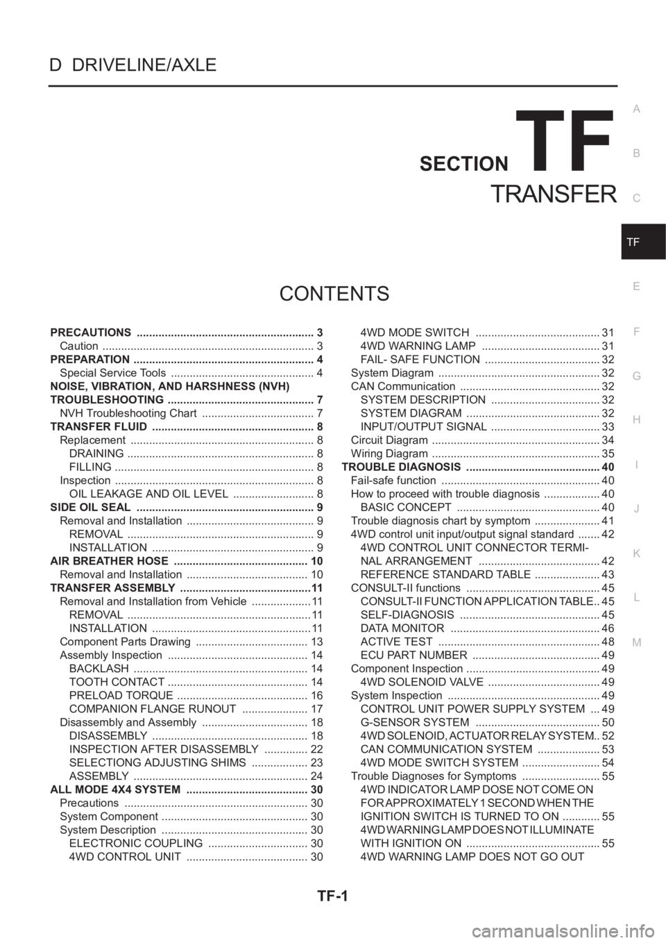
TF-1
TRANSFER
D DRIVELINE/AXLE
CONTENTS
C
E
F
G
H
I
J
K
L
M
SECTION
A
B
TF
TRANSFER
PRECAUTIONS .......................................................... 3
Caution ..................................................................... 3
PREPARATION ........................................................... 4
Special Service Tools ............................................... 4
NOISE, VIBRATION, AND HARSHNESS (NVH)
TROUBLESHOOTING ................................................ 7
NVH Troubleshooting Chart ..................................... 7
TRANSFER FLUID ..................................................... 8
Replacement ............................................................ 8
DRAINING ............................................................. 8
FILLING ................................................................. 8
Inspection ................................................................. 8
OIL LEAKAGE AND OIL LEVEL ........................... 8
SIDE OIL SEAL .......................................................... 9
Removal and Installation .......................................... 9
REMOVAL ............................................................. 9
INSTALLATION ..................................................... 9
AIR BREATHER HOSE ............................................ 10
Removal and Installation ........................................ 10
TRANSFER ASSEMBLY ...........................................11
Removal and Installation from Vehicle .................... 11
REMOVAL ............................................................ 11
INSTALLATION .................................................... 11
Component Parts Drawing ..................................... 13
Assembly Inspection .............................................. 14
BACKLASH ......................................................... 14
TOOTH CONTACT .............................................. 14
PRELOAD TORQUE ........................................... 16
COMPANION FLANGE RUNOUT ...................... 17
Disassembly and Assembly ................................... 18
DISASSEMBLY ................................................... 18
INSPECTION AFTER DISASSEMBLY ............... 22
SELECTIONG ADJUSTING SHIMS ................... 23
ASSEMBLY ......................................................... 24
ALL MODE 4X4 SYSTEM ........................................ 30
Precautions ............................................................ 30
System Component ................................................ 30
System Description ................................................ 30
ELECTRONIC COUPLING ................................. 30
4WD CONTROL UNIT ........................................ 304WD MODE SWITCH ......................................... 31
4WD WARNING LAMP ....................................... 31
FAIL- SAFE FUNCTION ...................................... 32
System Diagram ..................................................... 32
CAN Communication ...........................................
... 32
SYSTEM DESCRIPTION .................................... 32
SYSTEM DIAGRAM ............................................ 32
INPUT/OUTPUT SIGNAL .................................... 33
Circuit Diagram ....................................................... 34
Wiring Diagram ....................................................... 35
TROUBLE DIAGNOSIS ............................................ 40
Fail-safe function .................................................... 40
How to proceed with trouble diagnosis ................... 40
BASIC CONCEPT ............................................... 40
Trouble diagnosis chart by symptom ...................... 41
4WD control unit input/output signal standard ........ 42
4WD CONTROL UNIT CONNECTOR TERMI-
NAL ARRANGEMENT ........................................ 42
REFERENCE STANDARD TABLE ...................... 43
CONSULT-II functions ............................................ 45
CONSULT-II FUNCTION APPLICATION TABLE ... 45
SELF-DIAGNOSIS .............................................. 45
DATA MONITOR ................................................. 46
ACTIVE TEST ..................................................... 48
ECU PART NUMBER .......................................... 49
Component Inspection ............................................ 49
4WD SOLENOID VALVE ..................................... 49
System Inspection .................................................. 49
CONTROL UNIT POWER SUPPLY SYSTEM .... 49
G-SENSOR SYSTEM ......................................... 50
4WD SOLENOID, ACTUATOR RELAY SYSTEM ... 52
CAN COMMUNICATION SYSTEM ..................... 53
4WD MODE SWITCH SYSTEM .......................... 54
Trouble Diagnoses for Symptoms .......................... 55
4WD INDICATOR LAMP DOSE NOT COME ON
FOR APPROXIMATELY 1 SECOND WHEN THE
IGNITION SWITCH IS TURNED TO ON ............. 55
4WD WARNING LAMP DOES NOT ILLUMINATE
WITH IGNITION ON ............................................ 55
4WD WARNING LAMP DOES NOT GO OUT
Page 2642 of 3833

TF-32
ALL MODE 4X4 SYSTEM
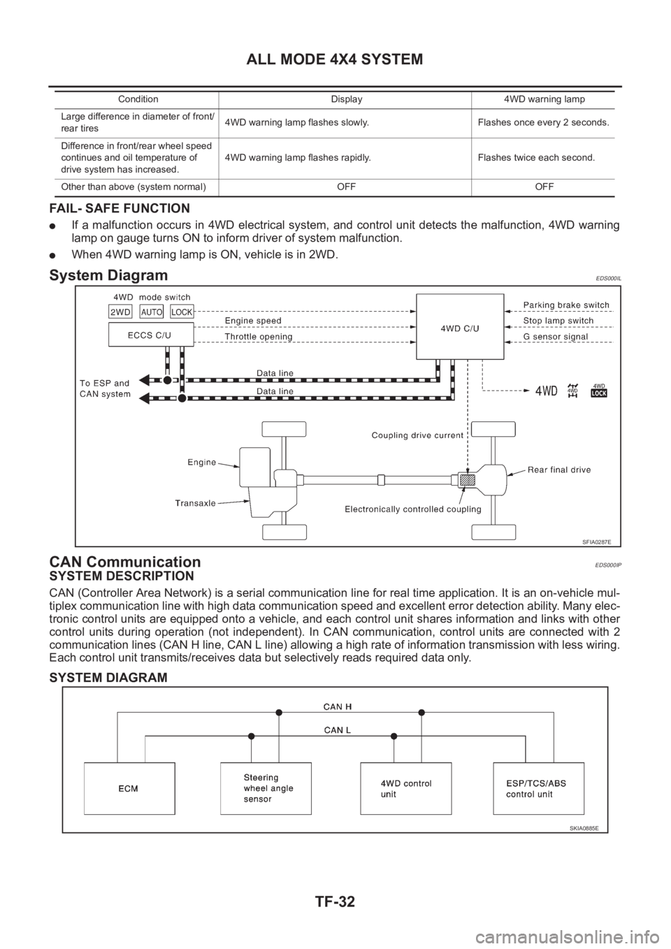
FAIL- SAFE FUNCTION
●If a malfunction occurs in 4WD electrical system, and control unit detects the malfunction, 4WD warning
lamp on gauge turns ON to inform driver of system malfunction.
●When 4WD warning lamp is ON, vehicle is in 2WD.
System DiagramEDS000IL
CAN CommunicationEDS000IP
SYSTEM DESCRIPTION
CAN (Controller Area Network) is a serial communication line for real time application. It is an on-vehicle mul-
tiplex communication line with high data communication speed and excellent error detection ability. Many elec-
tronic control units are equipped onto a vehicle, and each control unit shares information and links with other
control units during operation (not independent). In CAN communication, control units are connected with 2
communication lines (CAN H line, CAN L line) allowing a high rate of information transmission with less wiring.
Each control unit transmits/receives data but selectively reads required data only.
SYSTEM DIAGRAM
Large difference in diameter of front/
rear tires4WD warning lamp flashes slowly. Flashes once every 2 seconds.
Difference in front/rear wheel speed
continues and oil temperature of
drive system has increased.4WD warning lamp flashes rapidly. Flashes twice each second.
Other than above (system normal) OFF OFFCondition Display 4WD warning lamp
SFIA0287E
SKIA0885E
Page 2644 of 3833
TF-34
ALL MODE 4X4 SYSTEM
Circuit Diagram
EDS000IM
TDWA0007E
Page 2645 of 3833
ALL MODE 4X4 SYSTEM
TF-35
C
E
F
G
H
I
J
K
L
MA
B
TF
Wiring DiagramEDS000IN
TDWA0002E
Page 2653 of 3833

TROUBLE DIAGNOSIS
TF-43
C
E
F
G
H
I
J
K
L
MA
B
TF
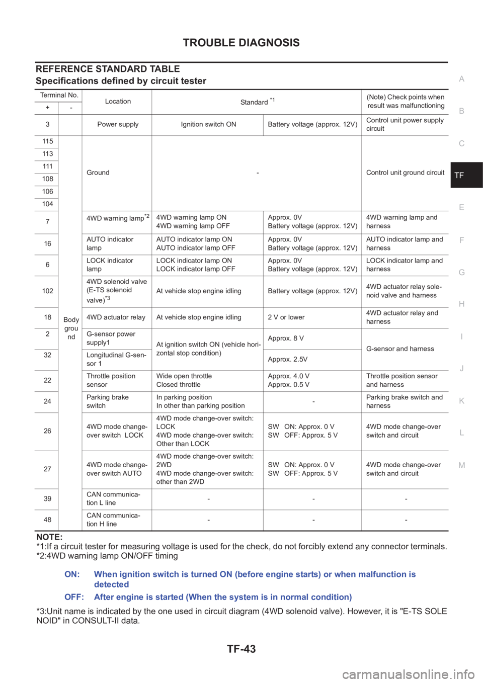
REFERENCE STANDARD TABLE
Specifications defined by circuit tester
NOTE:
*1:If a circuit tester for measuring voltage is used for the check, do not forcibly extend any connector terminals.
*2:4WD warning lamp ON/OFF timing
*3:Unit name is indicated by the one used in circuit diagram (4WD solenoid valve). However, it is "E-TS SOLE
NOID" in CONSULT-II data.
Terminal No.
Location
Standard *1(Note) Check points when
result was malfunctioning
+-
3 Power supply Ignition switch ON Battery voltage (approx. 12V)Control unit power supply
circuit
11 5
Body
grou
ndGround - Control unit ground circuit 11 3
111
108
106
104
74WD warning lamp
*24WD warning lamp ON
4WD warning lamp OFFApprox. 0V
Battery voltage (approx. 12V)4WD warning lamp and
harness
16AUTO indicator
lampAUTO indicator lamp ON
AUTO indicator lamp OFFApprox. 0V
Battery voltage (approx. 12V)AUTO indicator lamp and
harness
6LOCK indicator
lampLOCK indicator lamp ON
LOCK indicator lamp OFFApprox. 0V
Battery voltage (approx. 12V)LOCK indicator lamp and
harness
1024WD solenoid valve
(E-TS solenoid
valve)
*3At vehicle stop engine idling Battery voltage (approx. 12V)4WD actuator relay sole-
noid valve and harness
18 4WD actuator relay At vehicle stop engine idling 2 V or lower4WD actuator relay and
harness
2 G-sensor power
supply1
At ignition switch ON (vehicle hori-
zontal stop condition)Approx. 8 V
G-sensor and harness
32 Longitudinal G-sen-
sor 1Approx. 2.5V
22Throttle position
sensorWide open throttle
Closed throttleApprox. 4.0 V
Approx. 0.5 VThrottle position sensor
and harness
24Parking brake
switchIn parking position
In other than parking position-Parking brake switch and
harness
264WD mode change-
over switch LOCK4WD mode change-over switch:
LOCK
4WD mode change-over switch:
Other than LOCKSW ON: Approx. 0 V
SW OFF: Approx. 5 V4WD mode change-over
switch and circuit
274WD mode change-
over switch AUTO4WD mode change-over switch:
2WD
4WD mode change-over switch:
other than 2WDSW ON: Approx. 0 V
SW OFF: Approx. 5 V4WD mode change-over
switch and circuit
39CAN communica-
tion L line---
48CAN communica-
tion H line---
ON: When ignition switch is turned ON (before engine starts) or when malfunction is
detected
OFF: After engine is started (When the system is in normal condition)