2001 NISSAN X-TRAIL engine control
[x] Cancel search: engine controlPage 2101 of 3833
OVERALL SYSTEM
AT-23
D
E
F
G
H
I
J
K
L
MA
B
AT
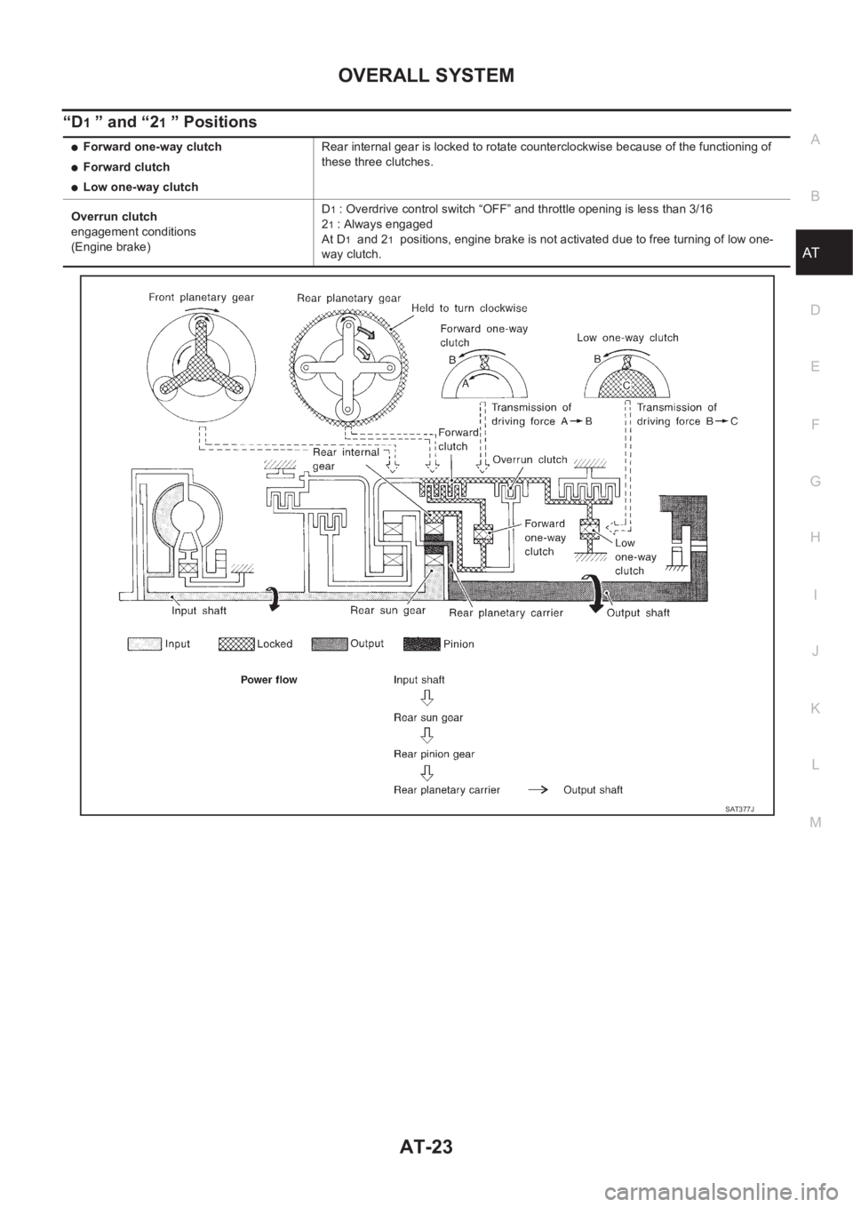
“D1 ” and “21 ” Positions
●Forward one-way clutch
●Forward clutch
●Low one-way clutchRear internal gear is locked to rotate counterclockwise because of the functioning of
these three clutches.
Overrun clutch
engagement conditions
(Engine brake)D
1 : Overdrive control switch “OFF” and throttle opening is less than 3/16
2
1 : Always engaged
At D
1 and 21 positions, engine brake is not activated due to free turning of low one-
way clutch.
SAT377J
Page 2106 of 3833
AT-28
OVERALL SYSTEM
Control System
ECS004QE
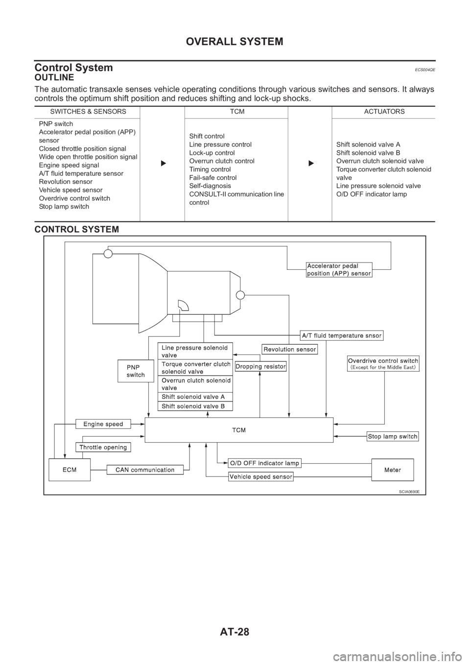
OUTLINE
The automatic transaxle senses vehicle operating conditions through various switches and sensors. It always
controls the optimum shift position and reduces shifting and lock-up shocks.
CONTROL SYSTEM
SWITCHES & SENSORS TCM ACTUATORS
PNP switch
Accelerator pedal position (APP)
sensor
Closed throttle position signal
Wide open throttle position signal
Engine speed signal
A/T fluid temperature sensor
Revolution sensor
Vehicle speed sensor
Overdrive control switch
Stop lamp switchShift control
Line pressure control
Lock-up control
Overrun clutch control
Timing control
Fail-safe control
Self-diagnosis
CONSULT-II communication line
controlShift solenoid valve A
Shift solenoid valve B
Overrun clutch solenoid valve
Torque converter clutch solenoid
valve
Line pressure solenoid valve
O/D OFF indicator lamp
SCIA0690E
Page 2107 of 3833
OVERALL SYSTEM
AT-29
D
E
F
G
H
I
J
K
L
MA
B
AT
TCM FUNCTION
The function of the TCM is to:
●Receive input signals sent from various switches and sensors.
●Determine required line pressure, shifting point, lock-up operation, and engine brake operation.
●Send required output signals to the respective solenoids.
INPUT/OUTPUT SIGNAL OF TCM
Control MechanismECS004QF
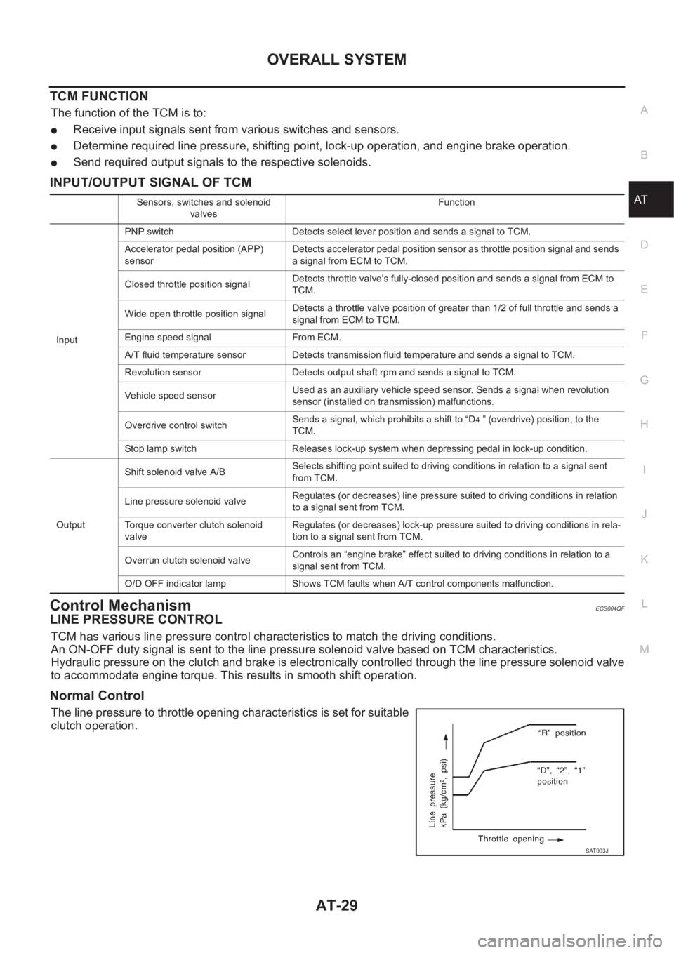
LINE PRESSURE CONTROL
TCM has various line pressure control characteristics to match the driving conditions.
An ON-OFF duty signal is sent to the line pressure solenoid valve based on TCM characteristics.
Hydraulic pressure on the clutch and brake is electronically controlled through the line pressure solenoid valve
to accommodate engine torque. This results in smooth shift operation.
Normal Control
The line pressure to throttle opening characteristics is set for suitable
clutch operation.
Sensors, switches and solenoid
valvesFunction
InputPNP switch Detects select lever position and sends a signal to TCM.
Accelerator pedal position (APP)
sensorDetects accelerator pedal position sensor as throttle position signal and sends
a signal from ECM to TCM.
Closed throttle position signalDetects throttle valve's fully-closed position and sends a signal from ECM to
TCM.
Wide open throttle position signalDetects a throttle valve position of greater than 1/2 of full throttle and sends a
signal from ECM to TCM.
Engine speed signal From ECM.
A/T fluid temperature sensor Detects transmission fluid temperature and sends a signal to TCM.
Revolution sensor Detects output shaft rpm and sends a signal to TCM.
Vehicle speed sensorUsed as an auxiliary vehicle speed sensor. Sends a signal when revolution
sensor (installed on transmission) malfunctions.
Overdrive control switchSends a signal, which prohibits a shift to “D
4 ” (overdrive) position, to the
TCM.
Stop lamp switch Releases lock-up system when depressing pedal in lock-up condition.
OutputShift solenoid valve A/BSelects shifting point suited to driving conditions in relation to a signal sent
from TCM.
Line pressure solenoid valveRegulates (or decreases) line pressure suited to driving conditions in relation
to a signal sent from TCM.
Torque converter clutch solenoid
valveRegulates (or decreases) lock-up pressure suited to driving conditions in rela-
tion to a signal sent from TCM.
Overrun clutch solenoid valveControls an “engine brake” effect suited to driving conditions in relation to a
signal sent from TCM.
O/D OFF indicator lamp Shows TCM faults when A/T control components malfunction.
SAT003J
Page 2108 of 3833
AT-30
OVERALL SYSTEM
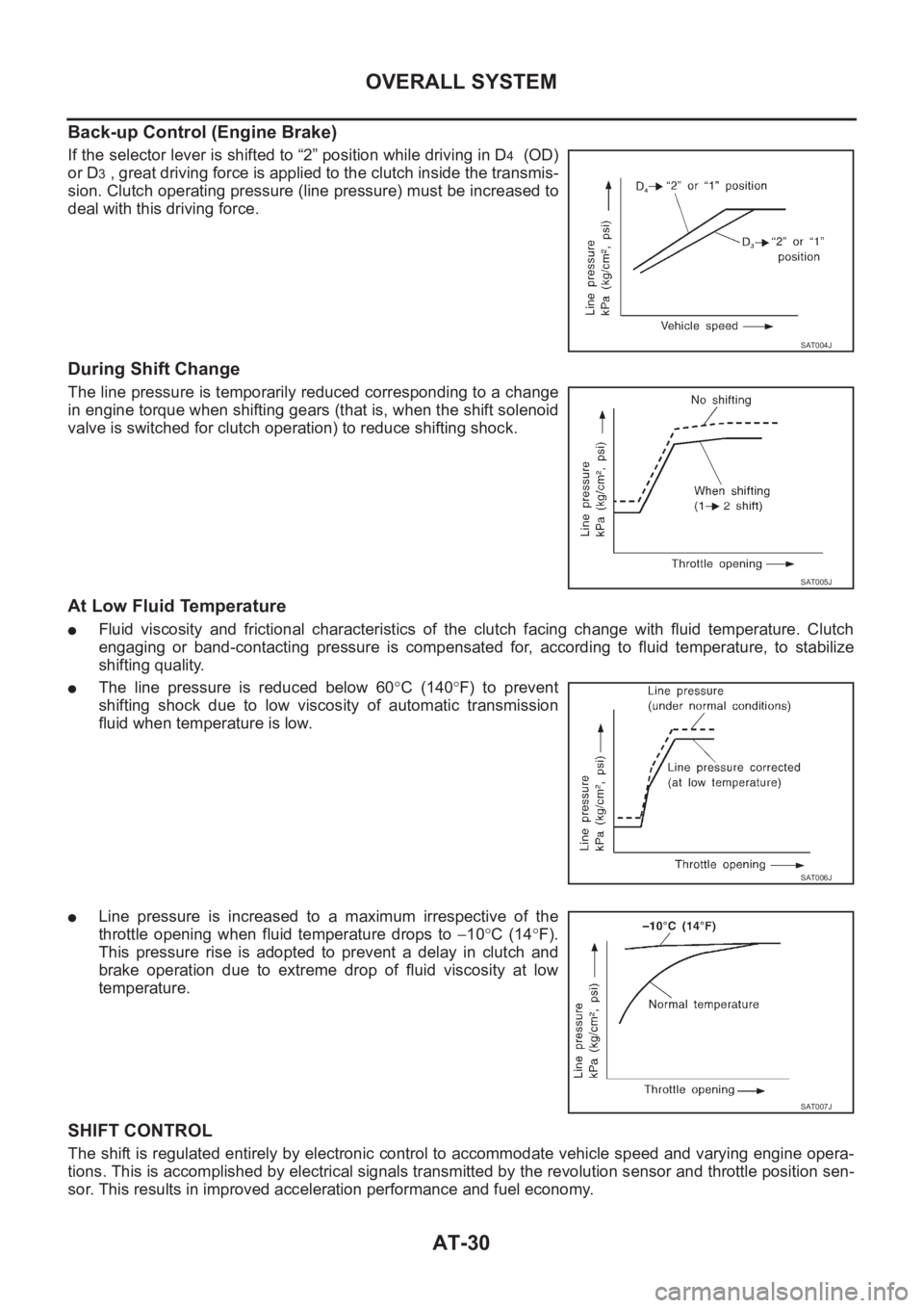
Back-up Control (Engine Brake)
If the selector lever is shifted to “2” position while driving in D4 (OD)
or D
3 , great driving force is applied to the clutch inside the transmis-
sion. Clutch operating pressure (line pressure) must be increased to
deal with this driving force.
During Shift Change
The line pressure is temporarily reduced corresponding to a change
in engine torque when shifting gears (that is, when the shift solenoid
valve is switched for clutch operation) to reduce shifting shock.
At Low Fluid Temperature
●Fluid viscosity and frictional characteristics of the clutch facing change with fluid temperature. Clutch
engaging or band-contacting pressure is compensated for, according to fluid temperature, to stabilize
shifting quality.
●The line pressure is reduced below 60°C (140°F) to prevent
shifting shock due to low viscosity of automatic transmission
fluid when temperature is low.
●Line pressure is increased to a maximum irrespective of the
throttle opening when fluid temperature drops to −10°C (14°F).
This pressure rise is adopted to prevent a delay in clutch and
brake operation due to extreme drop of fluid viscosity at low
temperature.
SHIFT CONTROL
The shift is regulated entirely by electronic control to accommodate vehicle speed and varying engine opera-
tions. This is accomplished by electrical signals transmitted by the revolution sensor and throttle position sen-
sor. This results in improved acceleration performance and fuel economy.
SAT004J
SAT005J
SAT006J
SAT007J
Page 2110 of 3833
AT-32
OVERALL SYSTEM
Torque Converter Clutch Solenoid Valve Control
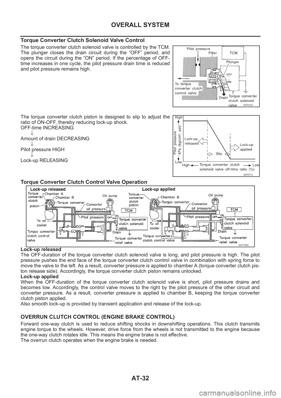
The torque converter clutch solenoid valve is controlled by the TCM.
The plunger closes the drain circuit during the “OFF” period, and
opens the circuit during the “ON” period. If the percentage of OFF-
time increases in one cycle, the pilot pressure drain time is reduced
and pilot pressure remains high.
The torque converter clutch piston is designed to slip to adjust the
ratio of ON-OFF, thereby reducing lock-up shock.
OFF-time INCREASING
↓
Amount of drain DECREASING
↓
Pilot pressure HIGH
↓
Lock-up RELEASING
Torque Converter Clutch Control Valve Operation
Lock-up released
The OFF-duration of the torque converter clutch solenoid valve is long, and pilot pressure is high. The pilot
pressure pushes the end face of the torque converter clutch control valve in combination with spring force to
move the valve to the left. As a result, converter pressure is applied to chamber A (torque converter clutch pis-
ton release side). Accordingly, the torque converter clutch piston remains unlocked.
Lock-up applied
When the OFF-duration of the torque converter clutch solenoid valve is short, pilot pressure drains and
becomes low. Accordingly, the control valve moves to the right by the pilot pressure of the other circuit and
converter pressure. As a result, converter pressure is applied to chamber B, keeping the torque converter
clutch piston applied.
Also smooth lock-up is provided by transient application and release of the lock-up.
OVERRUN CLUTCH CONTROL (ENGINE BRAKE CONTROL)
Forward one-way clutch is used to reduce shifting shocks in downshifting operations. This clutch transmits
engine torque to the wheels. However, drive force from the wheels is not transmitted to the engine because
the one-way clutch rotates idle. This means the engine brake is not effective.
The overrun clutch operates when the engine brake is needed.
SAT010J
SAT011J
AAT155A
Page 2111 of 3833
OVERALL SYSTEM
AT-33
D
E
F
G
H
I
J
K
L
MA
B
AT
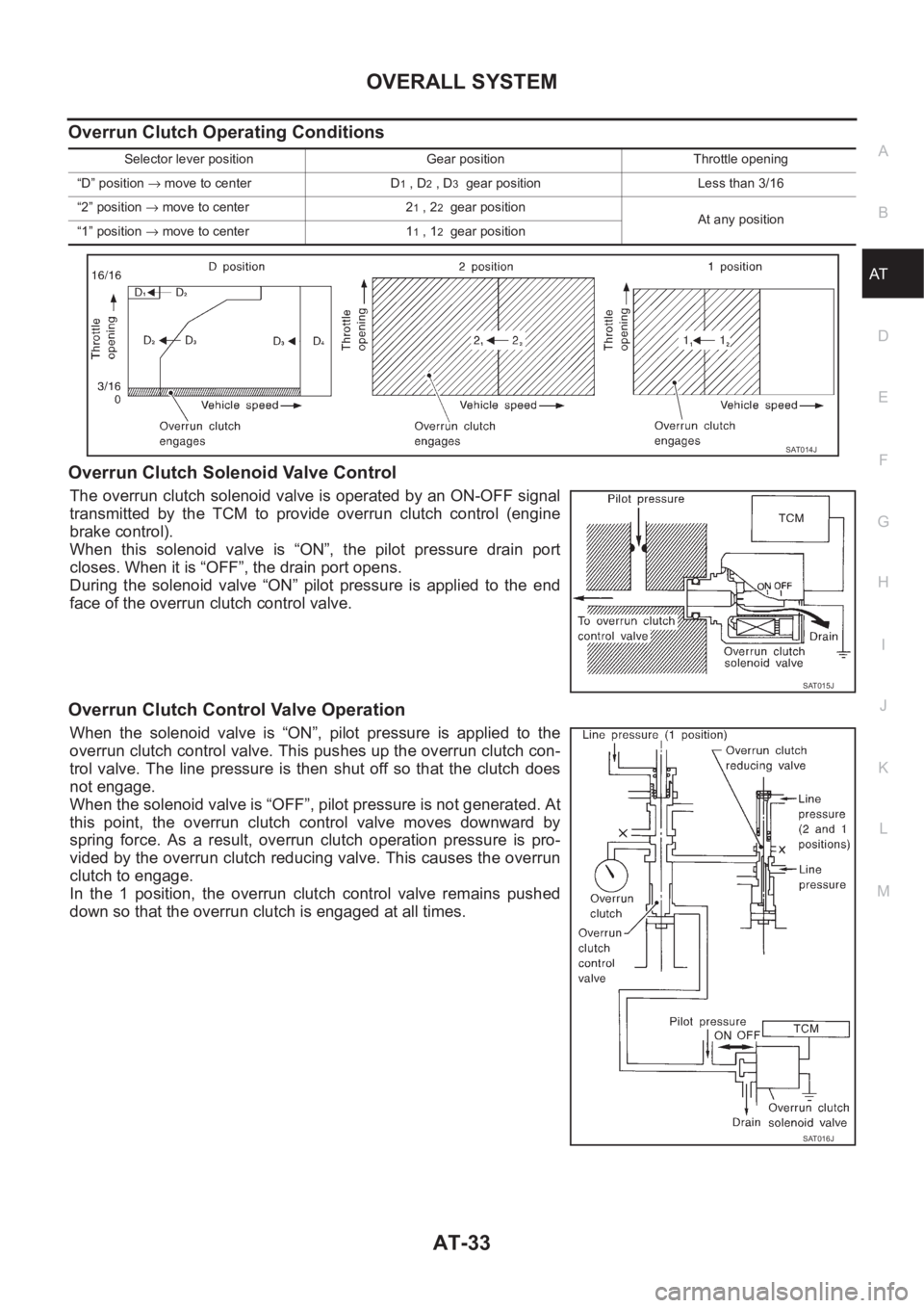
Overrun Clutch Operating Conditions
Overrun Clutch Solenoid Valve Control
The overrun clutch solenoid valve is operated by an ON-OFF signal
transmitted by the TCM to provide overrun clutch control (engine
brake control).
When this solenoid valve is “ON”, the pilot pressure drain port
closes. When it is “OFF”, the drain port opens.
During the solenoid valve “ON” pilot pressure is applied to the end
face of the overrun clutch control valve.
Overrun Clutch Control Valve Operation
When the solenoid valve is “ON”, pilot pressure is applied to the
overrun clutch control valve. This pushes up the overrun clutch con-
trol valve. The line pressure is then shut off so that the clutch does
not engage.
When the solenoid valve is “OFF”, pilot pressure is not generated. At
this point, the overrun clutch control valve moves downward by
spring force. As a result, overrun clutch operation pressure is pro-
vided by the overrun clutch reducing valve. This causes the overrun
clutch to engage.
In the 1 position, the overrun clutch control valve remains pushed
down so that the overrun clutch is engaged at all times.
Selector lever position Gear position Throttle opening
“D” position → move to center D
1 , D2 , D3 gear position Less than 3/16
“2” position → move to center 2
1 , 22 gear position
At any position
“1” position → move to center 1
1 , 12 gear position
SAT014J
SAT015J
SAT016J
Page 2112 of 3833
AT-34
OVERALL SYSTEM
Control Valve
ECS004QG
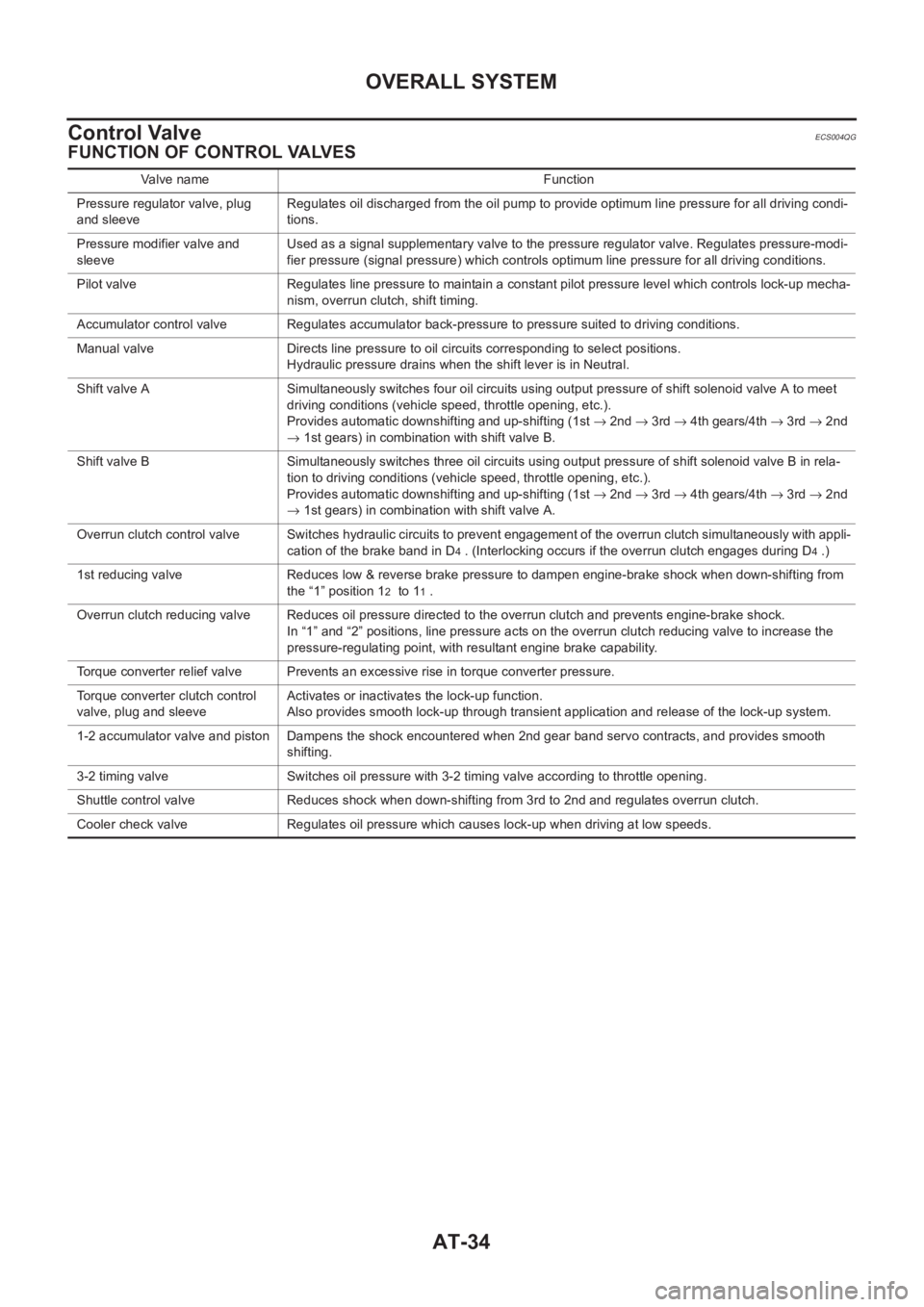
FUNCTION OF CONTROL VALVES
Valve name Function
Pressure regulator valve, plug
and sleeveRegulates oil discharged from the oil pump to provide optimum line pressure for all driving condi-
tions.
Pressure modifier valve and
sleeveUsed as a signal supplementary valve to the pressure regulator valve. Regulates pressure-modi-
fier pressure (signal pressure) which controls optimum line pressure for all driving conditions.
Pilot valve Regulates line pressure to maintain a constant pilot pressure level which controls lock-up mecha-
nism, overrun clutch, shift timing.
Accumulator control valve Regulates accumulator back-pressure to pressure suited to driving conditions.
Manual valve Directs line pressure to oil circuits corresponding to select positions.
Hydraulic pressure drains when the shift lever is in Neutral.
Shift valve A Simultaneously switches four oil circuits using output pressure of shift solenoid valve A to meet
driving conditions (vehicle speed, throttle opening, etc.).
Provides automatic downshifting and up-shifting (1st → 2nd → 3rd → 4th gears/4th → 3rd → 2nd
→ 1st gears) in combination with shift valve B.
Shift valve B Simultaneously switches three oil circuits using output pressure of shift solenoid valve B in rela-
tion to driving conditions (vehicle speed, throttle opening, etc.).
Provides automatic downshifting and up-shifting (1st → 2nd → 3rd → 4th gears/4th → 3rd → 2nd
→ 1st gears) in combination with shift valve A.
Overrun clutch control valve Switches hydraulic circuits to prevent engagement of the overrun clutch simultaneously with appli-
cation of the brake band in D
4 . (Interlocking occurs if the overrun clutch engages during D4 .)
1st reducing valve Reduces low & reverse brake pressure to dampen engine-brake shock when down-shifting from
the “1” position 1
2 to 11 .
Overrun clutch reducing valve Reduces oil pressure directed to the overrun clutch and prevents engine-brake shock.
In “1” and “2” positions, line pressure acts on the overrun clutch reducing valve to increase the
pressure-regulating point, with resultant engine brake capability.
Torque converter relief valve Prevents an excessive rise in torque converter pressure.
Torque converter clutch control
valve, plug and sleeveActivates or inactivates the lock-up function.
Also provides smooth lock-up through transient application and release of the lock-up system.
1-2 accumulator valve and piston Dampens the shock encountered when 2nd gear band servo contracts, and provides smooth
shifting.
3-2 timing valve Switches oil pressure with 3-2 timing valve according to throttle opening.
Shuttle control valve Reduces shock when down-shifting from 3rd to 2nd and regulates overrun clutch.
Cooler check valve Regulates oil pressure which causes lock-up when driving at low speeds.
Page 2121 of 3833
![NISSAN X-TRAIL 2001 Service Repair Manual ON BOARD DIAGNOSTIC SYSTEM DESCRIPTION
AT-43
[EURO-OBD]
D
E
F
G
H
I
J
K
L
MA
B
AT
X: Applicable
—: Not applicable
*1: These malfunctions cannot be displayed by MIL if another malfunction is assigned NISSAN X-TRAIL 2001 Service Repair Manual ON BOARD DIAGNOSTIC SYSTEM DESCRIPTION
AT-43
[EURO-OBD]
D
E
F
G
H
I
J
K
L
MA
B
AT
X: Applicable
—: Not applicable
*1: These malfunctions cannot be displayed by MIL if another malfunction is assigned](/manual-img/5/57405/w960_57405-2120.png)
ON BOARD DIAGNOSTIC SYSTEM DESCRIPTION
AT-43
[EURO-OBD]
D
E
F
G
H
I
J
K
L
MA
B
AT
X: Applicable
—: Not applicable
*1: These malfunctions cannot be displayed by MIL if another malfunction is assigned to lamp MIL.
*2: Refer to EC-58, "
Malfunction Indicator (MI)" (QR25DE) or EC-790, "Malfunction Indicator (MI)" (QR20DE). Overrun clutch solenoid valve
●TCM detects an improper voltage
drop when it tries to operate the
solenoid valve.X P1760
OVERRUN CLUTCH
S/VO/R CLUCH SOL/
CIRC
T/C clutch solenoid valve
●TCM detects an improper voltage
drop when it tries to operate the
solenoid valve.X P0740
T/C CLUTCH SOL/V TCC SOLENOID/
CIRC
Line pressure solenoid valve
●TCM detects an improper voltage
drop when it tries to operate the
solenoid valve.X P0745
LINE PRESSURE S/
VL/PRESS SOL/CIRC
Accelerator pedal position (APP) sensor
●TCM receives an excessively low
or high voltage from the sensor.
X P1705
THROTTLE POSI
SENTP SEN/CIRC A/T
Engine speed signal
●TCM does not receive the proper
voltage signal from the ECM.X P0725
ENGINE SPEED SIG
A/T fluid temperature sensor
●TCM receives an excessively low
or high voltage from the sensor.
X P0710
BATT/FLUID TEMP
SENATF TEMP SEN/
CIRC
CAN communication
●When a malfunction is detected in
CAN communication line
X U1000
CAN COMM CIR-
CUIT—
TCM (RAM)
●TCM memory (RAM) is malfunc-
tioning.
——
CONTROL UNIT
(RAM)—
TCM (ROM)
●TCM memory (ROM) is malfunc-
tioning.
——
CONTROL UNIT
(ROM)—
TCM (EEP ROM)
●TCM memory (EEP ROM) is mal-
functioning.
——
CONT UNIT (EEP
ROM)— Detected items
(Screen terms for CONSULT-II, “SELF
DIAGNOSIS” test mode)
Malfunction is detected when...TCM self-diagnosis EURO-OBD (DTC)
Available by O/D OFF
indicator lampAvailable by malfunc-
tion indicator*2,
“ENGINE” on CON-
SULT-II or GST “A/T” “ENGINE”