2001 NISSAN X-TRAIL engine control
[x] Cancel search: engine controlPage 1940 of 3833
![NISSAN X-TRAIL 2001 Service Repair Manual FL-16
[YD22DDTi]
FUEL FILTER
Air Bleeding
EBS00BLB
After fuel filter is replaced and after fuel system components are
removed/installed, bleed air from fuel path as follows:
1. Move priming p NISSAN X-TRAIL 2001 Service Repair Manual FL-16
[YD22DDTi]
FUEL FILTER
Air Bleeding
EBS00BLB
After fuel filter is replaced and after fuel system components are
removed/installed, bleed air from fuel path as follows:
1. Move priming p](/manual-img/5/57405/w960_57405-1939.png)
FL-16
[YD22DDTi]
FUEL FILTER
Air Bleeding
EBS00BLB
After fuel filter is replaced and after fuel system components are
removed/installed, bleed air from fuel path as follows:
1. Move priming pump up and down to bleed air from fuel path.
2. When air is bled, pumping of priming pump becomes heavy stop
operation at that time.
3. Crank the engine until it starts. Do not crank the engine for more
than 30 seconds.
4. If the engine does not starts, stop cranking and repeat step 1
above.
5. If the engine does not operate smoothly after it has started, race
it two or three times.
6. If air cannot be bled easily (pumping of priming pump does not become heavy), disconnect feed-side of
hose between fuel filter and electronically controlled fuel injection pump. After that, operate priming pump
and confirm that fuel comes out.
CAUTION:
Prepare a tray to collect fuel. Prevent fuel from adhering to rubber parts, especially the engine
mount insulator.
Draining Water from Fuel FilterEBS00MRU
1. Prepare a tray at the drain hose open end.
2. Loosen drain cock, and operate priming pump to drain water
from fuel filter.
CAUTION:
●Water in filter is drained with fuel. Prepare larger capacity
pan than fuel filter volume.
●Drained water is mixed with fuel. Prevent fuel from adher-
ing to rubber parts such as engine mount insulator.
3. After draining, close drain cock by hand.
CAUTION:
If drain cock is tightened excessively, it may be damaged
and fuel will leak. Do not use tools to tighten drain cock.
4. Bleed air in fuel piping. Refer to FL-16, "
Air Bleeding" .
5. Start engine and check for fuel leakage.
SBIA0137E
SBIA0138E
Page 1955 of 3833
ACC-1
ACCELERATOR CONTROL SYSTEM
B ENGINE
CONTENTS
C
D
E
F
G
H
I
J
K
L
M
SECTION
A
ACC
ACCELERATOR CONTROL SYSTEM
ACCELERATOR CONTROL SYSTEM ...................... 2
Removal and Installation .......................................... 2
QR20DE AND QR25DE ........................................ 2
YD22DDTI ............................................................. 2
REMOVAL ............................................................. 2
INSTALLATION ..................................................... 3
INSPECTION AFTER INSTALLATION ................. 3SERVICE DATA AND SPECIFICATIONS (SDS) ........ 4
Tightening Torque ..................................................... 4
QR20DE AND QR25DE ........................................ 4
YD22DDTI ............................................................. 4
Page 1976 of 3833
CL-18
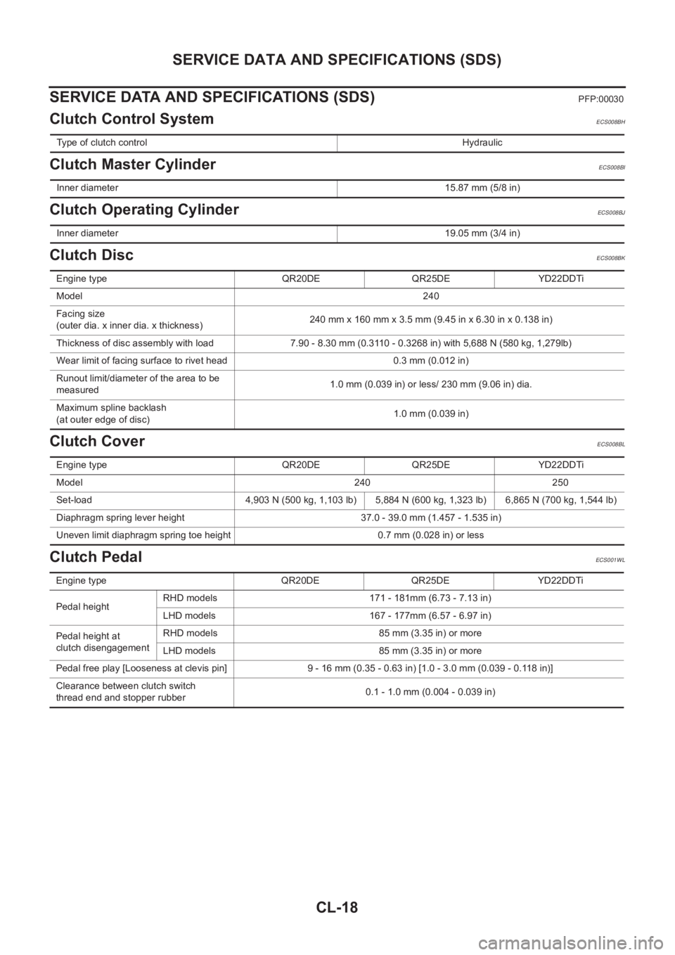
SERVICE DATA AND SPECIFICATIONS (SDS)
SERVICE DATA AND SPECIFICATIONS (SDS)
PFP:00030
Clutch Control SystemECS008BH
Clutch Master CylinderECS008BI
Clutch Operating CylinderECS008BJ
Clutch DiscECS008BK
Clutch CoverECS008BL
Clutch PedalECS001WL
Type of clutch controlHydraulic
Inner diameter15.87 mm (5/8 in)
Inner diameter19.05 mm (3/4 in)
Engine type QR20DE QR25DE YD22DDTi
Model240
Facing size
(outer dia. x inner dia. x thickness)240 mm x 160 mm x 3.5 mm (9.45 in x 6.30 in x 0.138 in)
Thickness of disc assembly with load 7.90 - 8.30 mm (0.3110 - 0.3268 in) with 5,688 N (580 kg, 1,279lb)
Wear limit of facing surface to rivet head 0.3 mm (0.012 in)
Runout limit/diameter of the area to be
measured1.0 mm (0.039 in) or less/ 230 mm (9.06 in) dia.
Maximum spline backlash
(at outer edge of disc)1.0 mm (0.039 in)
Engine type QR20DE QR25DE YD22DDTi
Model 240<0003000300030003000300030003000300030003000300030003000300030003000300030003000300030003000300030003000300030003000300030003000300030003000300030003000300030003000300030003000300030003000300030003000300
030003000300030003[ 250
Set-load 4,903 N (500 kg, 1,103 lb) 5,884 N (600 kg, 1,323 lb) 6,865 N (700 kg, 1,544 lb)
Diaphragm spring lever height 37.0 - 39.0 mm (1.457 - 1.535 in)
Uneven limit diaphragm spring toe height 0.7 mm (0.028 in) or less
Engine type QR20DE QR25DE YD22DDTi
Pedal height RHD models 171 - 181mm (6.73 - 7.13 in)
LHD models 167 - 177mm (6.57 - 6.97 in)
Pedal height at
clutch disengagement RHD models 85 mm (3.35 in) or more
LHD models 85 mm (3.35 in) or more
Pedal free play [Looseness at clevis pin] 9 - 16 mm (0.35 - 0.63 in) [1.0 - 3.0 mm (0.039 - 0.118 in)]
Clearance between clutch switch
thread end and stopper rubber 0.1 - 1.0 mm (0.004 - 0.039 in)
Page 1991 of 3833
TRANSAXLE ASSEMBLY
MT-15
D
E
F
G
H
I
J
K
L
MA
B
MT
TRANSAXLE ASSEMBLYPFP:32010
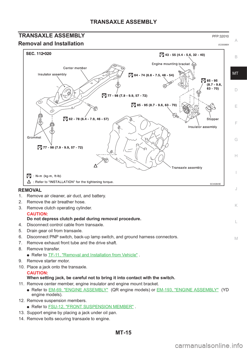
Removal and InstallationECS008BX
REMOVAL
1. Remove air cleaner, air duct, and battery.
2. Remove the air breather hose.
3. Remove clutch operating cylinder.
CAUTION:
Do not depress clutch pedal during removal procedure.
4. Disconnect control cable from transaxle.
5. Drain gear oil from transaxle.
6. Disconnect PNP switch, back-up lamp switch, and ground harness connectors.
7. Remove exhaust front tube and the drive shaft.
8. Remove transfer.
●Refer to TF-11, "Removal and Installation from Vehicle" .
9. Remove starter motor.
10. Place a jack onto the transaxle.
CAUTION:
When setting jack, be careful not to bring it into contact with the switch.
11. Remove center member, engine insulator and engine mount bracket.
●Refer to EM-69, "ENGINE ASSEMBLY" (QR engine models) or EM-193, "ENGINE ASSEMBLY" (YD
engine models).
12. Remove suspension members.
●Refer to FSU-12, "FRONT SUSPENSION MEMBER" .
13. Support engine by placing a jack under oil pan.
14. Remove bolts securing transaxle to engine.
SCIA0845E
Page 2079 of 3833
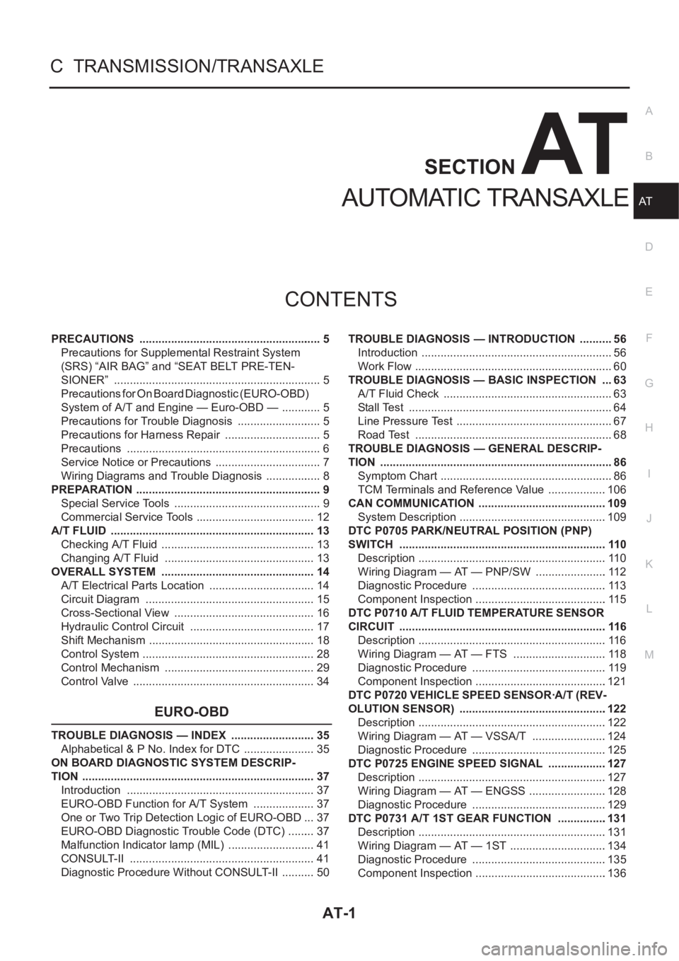
AT-1
AUTOMATIC TRANSAXLE
C TRANSMISSION/TRANSAXLE
CONTENTS
D
E
F
G
H
I
J
K
L
M
SECTION
A
B
AT
AUTOMATIC TRANSAXLE
PRECAUTIONS .......................................................... 5
Precautions for Supplemental Restraint System
(SRS) “AIR BAG” and “SEAT BELT PRE-TEN-
SIONER” .................................................................. 5
Precautions for On Board Diagnostic (EURO-OBD)
System of A/T and Engine — Euro-OBD — ............. 5
Precautions for Trouble Diagnosis ........................... 5
Precautions for Harness Repair ............................... 5
Precautions .............................................................. 6
Service Notice or Precautions .................................. 7
Wiring Diagrams and Trouble Diagnosis .................. 8
PREPARATION ........................................................... 9
Special Service Tools ............................................... 9
Commercial Service Tools ...................................... 12
A/T FLUID ................................................................. 13
Checking A/T Fluid ................................................. 13
Changing A/T Fluid ............................................. ... 13
OVERALL SYSTEM ................................................. 14
A/T Electrical Parts Location .................................. 14
Circuit Diagram ...................................................... 15
Cross-Sectional View ............................................. 16
Hydraulic Control Circuit ........................................ 17
Shift Mechanism ..................................................... 18
Control System ....................................................... 28
Control Mechanism ................................................ 29
Control Valve .......................................................... 34
EURO-OBD
TROUBLE DIAGNOSIS — INDEX ........................... 35
Alphabetical & P No. Index for DTC ....................... 35
ON BOARD DIAGNOSTIC SYSTEM DESCRIP-
TION .......................................................................... 37
Introduction ............................................................ 37
EURO-OBD Function for A/T System .................... 37
One or Two Trip Detection Logic of EURO-OBD ... 37
EURO-OBD Diagnostic Trouble Code (DTC) ......... 37
Malfunction Indicator lamp (MIL) ............................ 41
CONSULT-II ........................................................... 41
Diagnostic Procedure Without CONSULT-II ........... 50TROUBLE DIAGNOSIS — INTRODUCTION ........... 56
Introduction ............................................................. 56
Work Flow ............................................................... 60
TROUBLE DIAGNOSIS — BASIC INSPECTION .... 63
A/T Fluid Check ...................................................... 63
Stall Test ................................................................. 64
Line Pressure Test .................................................. 67
Road Test ............................................................... 68
TROUBLE DIAGNOSIS — GENERAL DESCRIP-
TION .......................................................................... 86
Symptom Chart ....................................................... 86
TCM Terminals and Reference Value ...................106
CAN COMMUNICATION .........................................109
System Description ...............................................109
DTC P0705 PARK/NEUTRAL POSITION (PNP)
SWITCH ..................................................................110
Description ............................................................110
Wiring Diagram — AT — PNP/SW .......................112
Diagnostic Procedure ...........................................113
Component Inspection ..........................................115
DTC P0710 A/T FLUID TEMPERATURE SENSOR
CIRCUIT ..................................................................116
Description ............................................................116
Wiring Diagram — AT — FTS ..............................118
Diagnostic Procedure ...........................................119
Component Inspection ..........................................121
DTC P0720 VEHICLE SPEED SENSOR·A/T (REV-
OLUTION SENSOR) ...............................................122
Description ............................................................122
Wiring Diagram — AT — VSSA/T ........................124
Diagnostic Procedure ...........................................125
DTC P0725 ENGINE SPEED SIGNAL ...................127
Description ............................................................127
Wiring Diagram — AT — ENGSS .........................128
Diagnostic Procedure ...........................................129
DTC P0731 A/T 1ST GEAR FUNCTION ...............
.131
Description ............................................................131
Wiring Diagram — AT — 1ST ...............................134
Diagnostic Procedure ...........................................135
Component Inspection ..........................................136
Page 2080 of 3833
AT-2
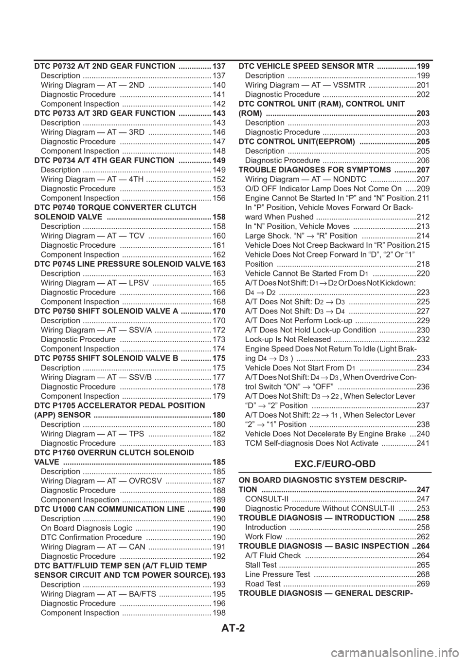
DTC P0732 A/T 2ND GEAR FUNCTION ................137
Description ............................................................137
Wiring Diagram — AT — 2ND ..............................140
Diagnostic Procedure ...........................................141
Component Inspection ..........................................142
DTC P0733 A/T 3RD GEAR FUNCTION ................143
Description ............................................................143
Wiring Diagram — AT — 3RD ..............................146
Diagnostic Procedure ...........................................147
Component Inspection ..........................................148
DTC P0734 A/T 4TH GEAR FUNCTION ................149
Description ............................................................149
Wiring Diagram — AT — 4TH ...............................152
Diagnostic Procedure ...........................................153
Component Inspection ..........................................156
DTC P0740 TORQUE CONVERTER CLUTCH
SOLENOID VALVE .................................................158
Description ............................................................158
Wiring Diagram — AT — TCV ..............................160
Diagnostic Procedure ...........................................161
Component Inspection ..........................................162
DTC P0745 LINE PRESSURE SOLENOID VALVE .163
Description ............................................................163
Wiring Diagram — AT — LPSV ............................165
Diagnostic Procedure ...........................................166
Component Inspection ..........................................168
DTC P0750 SHIFT SOLENOID VALVE A ...............170
Description ............................................................170
Wiring Diagram — AT — SSV/A ...........................172
Diagnostic Procedure ...........................................173
Component Inspection ..........................................174
DTC P0755 SHIFT SOLENOID VALVE B ...............175
Description ............................................................175
Wiring Diagram — AT — SSV/B ...........................177
Diagnostic Procedure ...........................................178
Component Inspection ..........................................179
DTC P1705 ACCELERATOR PEDAL POSITION
(APP) SENSOR .......................................................180
Description ............................................................180
Wiring Diagram — AT — TPS ..............................182
Diagnostic Procedure ...........................................183
DTC P1760 OVERRUN CLUTCH SOLENOID
VALVE .....................................................................185
Description ............................................................185
Wiring Diagram — AT — OVRCSV ......................187
Diagnostic Procedure ...........................................188
Component Inspection ..........................................189
DTC U1000 CAN COMMUNICATION LINE ...........
.190
Description ............................................................190
On Board Diagnosis Logic ....................................190
DTC Confirmation Procedure ...............................190
Wiring Diagram — AT — CAN ..............................191
Diagnostic Procedure ...........................................192
DTC BATT/FLUID TEMP SEN (A/T FLUID TEMP
SENSOR CIRCUIT AND TCM POWER SOURCE) .193
Description ............................................................193
Wiring Diagram — AT — BA/FTS .........................195
Diagnostic Procedure ...........................................196
Component Inspection ..........................................198DTC VEHICLE SPEED SENSOR MTR ...................199
Description ............................................................199
Wiring Diagram — AT — VSSMTR .......................201
Diagnostic Procedure ............................................202
DTC CONTROL UNIT (RAM), CONTROL UNIT
(ROM) ......................................................................203
Description ............................................................203
Diagnostic Procedure ............................................203
DTC CONTROL UNIT(EEPROM) ...........................205
Description ............................................................205
Diagnostic Procedure ............................................206
TROUBLE DIAGNOSES FOR SYMPTOMS ...........207
Wiring Diagram — AT — NONDTC ......................207
O/D OFF Indicator Lamp Does Not Come On ......209
Engine Cannot Be Started In “P” and “N” Position .211
In “P” Position, Vehicle Moves Forward Or Back-
ward When Pushed ...............................................212
In “N” Position, Vehicle Moves ..............................213
Large Shock. “N” → “R” Position ..........................214
Vehicle Does Not Creep Backward In “R” Position .215
Vehicle Does Not Creep Forward In “D”, “2” Or “1”
Position .................................................................218
Vehicle Cannot Be Started From D
1 .....................220
A/T Does Not Shift: D
1→ D2 Or Does Not Kickdown:
D
4→ D2 ...............................................................
.223
A/T Does Not Shift: D
2→ D3 ................................225
A/T Does Not Shift: D
3→ D4 ................................227
A/T Does Not Perform Lock-up .............................229
A/T Does Not Hold Lock-up Condition ..................230
Lock-up Is Not Released .......................................232
Engine Speed Does Not Return To Idle (Light Brak-
ing D
4→ D3 ) ........................................................233
Vehicle Does Not Start From D
1 ...........................234
A / T D o e s N o t S h i f t : D
4→ D3 , W h e n O v e r d r i v e C o n -
trol Switch “ON” → “OFF” .....................................236
A/T Does Not Shift: D
3→ 22 , W h e n S e l e c t o r L e v e r
“D” → “2” Position .................................................237
A/T Does Not Shift: 2
2→ 11 , When Selector Lever
“2” → “1” Position ..................................................238
Vehicle Does Not Decelerate By Engine Brake ....240
TCM Self-diagnosis Does Not Activate .................241
EXC.F/EURO-OBD
ON BOARD DIAGNOSTIC SYSTEM DESCRIP-
TION ........................................................................247
CONSULT-II ..........................................................247
Diagnostic Procedure Without CONSULT-II .........253
TROUBLE DIAGNOSIS — INTRODUCTION .........258
Introduction ...........................................................258
Work Flow .............................................................262
TROUBLE DIAGNOSIS — BASIC INSPECTION ...264
A/T Fluid Check ....................................................264
Stall Test ................................................................265
Line Pressure Test ................................................268
Road Test ..............................................................269
TROUBLE DIAGNOSIS — GENERAL DESCRIP-
Page 2081 of 3833
AT-3
D
E
F
G
H
I
J
K
L
MA
B
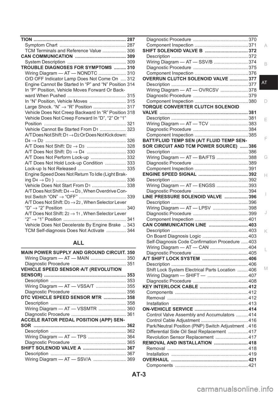
AT TION ........................................................................ 287
Symptom Chart .................................................... 287
TCM Terminals and Reference Value ................... 306
CAN COMMUNICATION ........................................ 309
System Description .............................................. 309
TROUBLE DIAGNOSES FOR SYMPTOMS .......... 310
Wiring Diagram — AT — NONDTC ...................... 310
O/D OFF Indicator Lamp Does Not Come On ..... 312
Engine Cannot Be Started In “P” and “N” Position . 314
In “P” Position, Vehicle Moves Forward Or Back-
ward When Pushed .............................................. 315
In “N” Position, Vehicle Moves ............................. 315
Large Shock. “N” → “R” Position .......................... 317
Vehicle Does Not Creep Backward In “R” Position . 318
Vehicle Does Not Creep Forward In “D”, “2” Or “1”
Position ................................................................ 321
Vehicle Cannot Be Started From D
1 ..................... 323
A/T Does Not Shift: D
1→ D2 Or Does Not Kick down:
D
4→ D2 ............................................................... 326
A/T Does Not Shift: D
2→ D3 ............................... 328
A/T Does Not Shift: D
3→ D4 ............................... 330
A/T Does Not Perform Lock-up ............................ 332
A/T Does Not Hold Lock-up Condition ................. 333
Lock-up Is Not Released ...................................... 335
Engine Speed Does Not Return To Idle (Light Brak-
ing D
4→ D3 ) ....................................................... 336
Vehicle Does Not Start From D
1 ........................... 338
A/T Does Not Shift: D
4→ D3 , When Overdrive Con-
trol Switch “ON” → “OFF” ..................................... 339
A/T Does Not Shift: D
3→ 22 , W h e n S e l e c t o r L e v e r
“D”→ “2” Position ................................................ 340
A/T Does Not Shift: 2
2→ 11 , W h e n S e l e c t o r L e v e r
“2” → “1” Position ................................................. 341
Vehicle Does Not Decelerate By Engine Brake ... 343
TCM Self-diagnosis Does Not Activate ................ 344
ALL
MAIN POWER SUPPLY AND GROUND CIRCUIT . 350
Wiring Diagram — AT — MAIN ............................ 350
Diagnostic Procedure ........................................... 351
VEHICLE SPEED SENSOR·A/T (REVOLUTION
SENSOR) ................................................................ 353
Description ........................................................... 353
Wiring Diagram — AT — VSSA/T ........................ 355
Diagnostic Procedure ........................................... 356
DTC VEHICLE SPEED SENSOR MTR .................. 358
Description ........................................................... 358
Wiring Diagram — AT — VSSMTR ...................... 360
Diagnostic Procedure ........................................... 361
ACCELE RATOR PEDAL POSITION (APP) SEN-
SOR ........................................................................ 362
Description ........................................................... 362
Wiring Diagram — AT — TPS .............................. 364
Diagnostic Procedure ........................................... 365
SHIFT SOLENOID VALVE A .................................. 367
Description ........................................................... 367
Wiring Diagram — AT — SSV/A .......................... 369Diagnostic Procedure ...........................................370
Component Inspection ..........................................371
SHIFT SOLENOID VALVE B ..................................372
Description ............................................................372
Wiring Diagram — AT — SSV/B ...........................374
Diagnostic Procedure ...........................................375
Component Inspection ..........................................376
OVERRUN CLUTCH SOLENOID VALVE ...............377
Description ............................................................377
Wiring Diagram — AT — OVRCSV ......................378
Diagnostic Procedure ...........................................379
Component Inspection ..........................................380
TORQUE CONVERTER CLUTCH SOLENOID
VALVE .....................................................................381
Description ............................................................381
Wiring Diagram — AT — TCV ..............................383
Diagnostic Procedure ...........................................384
Component Inspection ..........................................385
BATT/FLUID TEMP SEN (A/T FLUID TEMP SEN-
SOR CIRCUIT AND TCM POWER SOURCE) .......386
Description ............................................................386
Wiring Diagram — AT — BA/FTS .........................388
Diagnostic Procedure ...........................................389
Component Inspection ..........................................391
ENGINE SPEED SIGNAL .......................................392
Description ............................................................392
Wiring Diagram — AT — ENGSS .........................393
Diagnostic Procedure ...........................................394
LINE PRESSURE SOLENOID VALVE ..................
.396
Description ............................................................396
Wiring Diagram — AT — LPSV ............................398
Diagnostic Procedure ...........................................399
Component Inspection ..........................................401
CAN COMMUNICATION LINE ...............................403
Description ............................................................403
On Board Diagnosis Logic ....................................403
Self-Diagnosis Code Confirmation Procedure ......403
Wiring Diagram — AT — CAN ..............................404
Diagnostic Procedure ...........................................405
A/T SHIFT LOCK SYSTEM ....................................406
Description ............................................................406
Shift Lock System Electrical Parts Location .........406
Wiring Diagram — SHIFT — ................................407
Diagnostic Procedure ...........................................408
KEY INTERLOCK CABLE ......................................412
Components .........................................................412
Removal ...............................................................412
Installation ............................................................413
ON-VEHICLE SERVICE ..........................................414
Control Valve Assembly and Accumulators ..........414
Control Cable Adjustment .....................................416
Park/Neutral Position (PNP) Switch Adjustment ..416
Differential Side Oil Seal Replacement ................417
Revolution Sensor Replacement ..........................417
REMOVAL AND INSTALLATION ...........................418
Removal ...............................................................418
Installation ............................................................419
OVERHAUL ............................................................421
Components .........................................................421
Page 2097 of 3833
OVERALL SYSTEM
AT-19
D
E
F
G
H
I
J
K
L
MA
B
AT
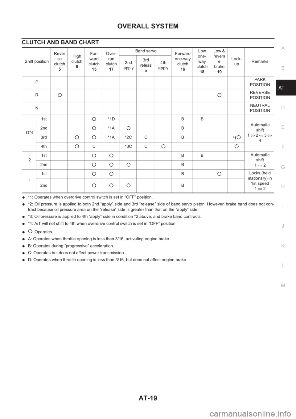
CLUTCH AND BAND CHART
●*1: Operates when overdrive control switch is set in “OFF” position.
●*2: Oil pressure is applied to both 2nd “apply” side and 3rd “release” side of band servo piston. However, brake band does not con-
tract because oil pressure area on the “release” side is greater than that on the “apply” side.
●*3: Oil pressure is applied to 4th “apply” side in condition *2 above, and brake band contracts.
●*4: A/T will not shift to 4th when overdrive control switch is set in “OFF” position.
●: Operates.
●A: Operates when throttle opening is less than 3/16, activating engine brake.
●B: Operates during “progressive” acceleration.
●C: Operates but does not affect power transmission.
●D: Operates when throttle opening is less than 3/16, but does not affect engine brake. Shift positionRever
se
clutch
5High
clutch
6For-
ward
clutch
15Over-
run
clutch
17Band servo
Forward
one-way
clutch
16Low
one-
way
clutch
18Low &
revers
e
brake
19Lock-
upRemarks
2nd
apply3rd
releas
e4th
apply
PPA R K
POSITION
RREVERSE
POSITION
NNEUTRAL
POSITION
D*41st *1D B B
Automatic
shift
1⇔ 2 ⇔ 3 ⇔
4 2nd *1A B
3rd *1A *2C C B
*1
4th C *3C C
21stBBAutomatic
shift
1⇔ 2 2ndB
11stBLocks (held
stationary) in
1st speed
1⇐ 2 2ndB