Page 2902 of 3833
![NISSAN X-TRAIL 2001 Service Repair Manual BRC-118
[ESP/TCS/ABS]
TROUBLE DIAGNOSIS
Symptom 7: SLIP Indicator Lamp Does Not Illuminate
EFS001AY
Inspection procedure
1. SLIP INDICATOR LAMP BURNED-OUT BULB INSPECTION
Check for continuity between NISSAN X-TRAIL 2001 Service Repair Manual BRC-118
[ESP/TCS/ABS]
TROUBLE DIAGNOSIS
Symptom 7: SLIP Indicator Lamp Does Not Illuminate
EFS001AY
Inspection procedure
1. SLIP INDICATOR LAMP BURNED-OUT BULB INSPECTION
Check for continuity between](/manual-img/5/57405/w960_57405-2901.png)
BRC-118
[ESP/TCS/ABS]
TROUBLE DIAGNOSIS
Symptom 7: SLIP Indicator Lamp Does Not Illuminate
EFS001AY
Inspection procedure
1. SLIP INDICATOR LAMP BURNED-OUT BULB INSPECTION
Check for continuity between the power supply terminal of meter and terminal of ABS warning lamp.
Is inspection result OK?
YES >> GO TO 2.
NO >> Circuit malfunction in SLIP indicator lamp or combination meter
2. SLIP INDICATOR LAMP POWER CIRCUIT INSPECTION
Disconnect the meter connector. Check that the voltage between the vehicle-side harness terminal and body
ground is battery voltage (Approx. 12V).
Is inspection result OK?
YES >> GO TO 3.
NO >>
●Fuse inspection
●Inspection for harness and connectors between fuse block and meter
●Check the power supply circuit (battery and ignition switch circuit).
3. SLIP INDICATOR LAMP HARNESS INSPECTION
1. Disconnect connectors for the ESP/TCS/ABS control unit and meter vehicle-side harness.
2. Check the harness between the meter and the ESP/TCS/ABS control unit for an open/shorted circuit.
Is inspection result OK?
YES >> GO TO 4.
NO >> Repair or replace the disconnected harness.
4. SLIP INDICATOR LAMP CONNECTOR INSPECTION
Check connectors for the ESP/TCS/ABS control unit and meter vehicle-side harness.
Is inspection result OK?
YES >> Connect connectors, and perform the self-diagnosis. The vehicle harness has the intermediate
connector. Refer to the vehicle wiring diagram, always check it.
NO >> Repair or replace the disconnected connector.
Symptom 8: During ESP/TCS/ABS Control, Vehicle Behavior is Jerky.EFS001AZ
Inspection procedure
1. ENGINE SPEED SIGNAL INSPECTION
Perform “DATA MONITOR” with CONSULT-II for the ESP/TCS/ABS control unit.
Is the engine speed at idle 400 rpm or higher?
YES >> Normal
NO >> GO TO 2.
2. SELF-DIAGNOSIS RESULT CHECK 1
Perform the ESP/TCS/ABS control unit self-diagnosis.
Is the self-diagnosis results displayed?
YES >> After checking and repairing the applicable item, perform the ESP/TCS/ABS control unit self-
diagnosis again.
NO >> GO TO 3.
Page 2921 of 3833

STEERING COLUMN
PS-11
C
D
E
F
H
I
J
K
L
MA
B
PS
Disassembly and AssemblyEGS00095
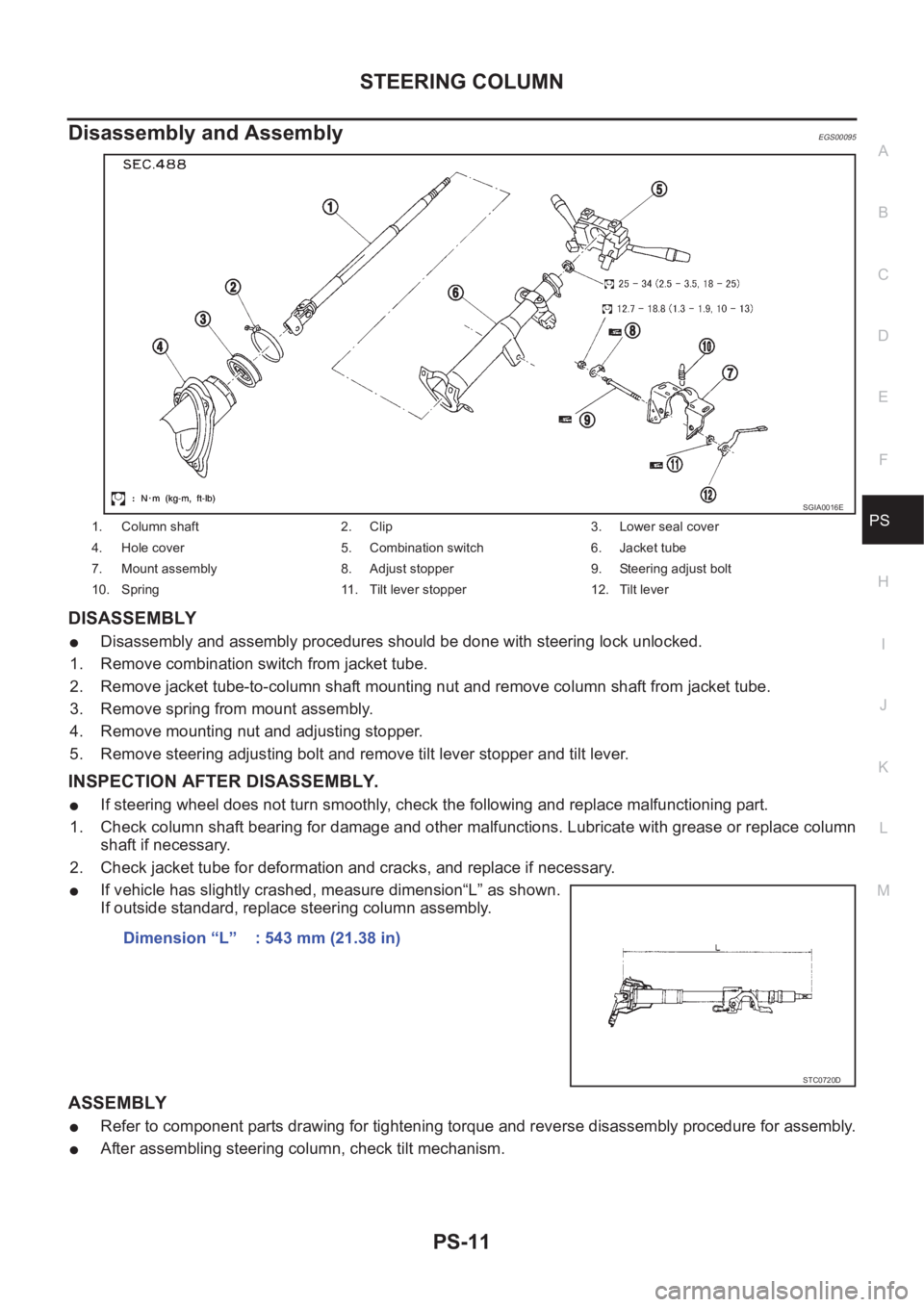
DISASSEMBLY
●Disassembly and assembly procedures should be done with steering lock unlocked.
1. Remove combination switch from jacket tube.
2. Remove jacket tube-to-column shaft mounting nut and remove column shaft from jacket tube.
3. Remove spring from mount assembly.
4. Remove mounting nut and adjusting stopper.
5. Remove steering adjusting bolt and remove tilt lever stopper and tilt lever.
INSPECTION AFTER DISASSEMBLY.
●If steering wheel does not turn smoothly, check the following and replace malfunctioning part.
1. Check column shaft bearing for damage and other malfunctions. Lubricate with grease or replace column
shaft if necessary.
2. Check jacket tube for deformation and cracks, and replace if necessary.
●If vehicle has slightly crashed, measure dimension“L” as shown.
If outside standard, replace steering column assembly.
ASSEMBLY
●Refer to component parts drawing for tightening torque and reverse disassembly procedure for assembly.
●After assembling steering column, check tilt mechanism.
1. Column shaft 2. Clip 3. Lower seal cover
4. Hole cover 5. Combination switch 6. Jacket tube
7. Mount assembly 8. Adjust stopper 9. Steering adjust bolt
10. Spring 11. Tilt lever stopper 12. Tilt lever
SGIA0016E
Dimension “L” : 543 mm (21.38 in)
STC0720D
Page 2988 of 3833

SB-6
SEAT BELT WARNING SYSTEM
SEAT BELT WARNING SYSTEM
PFP:25045
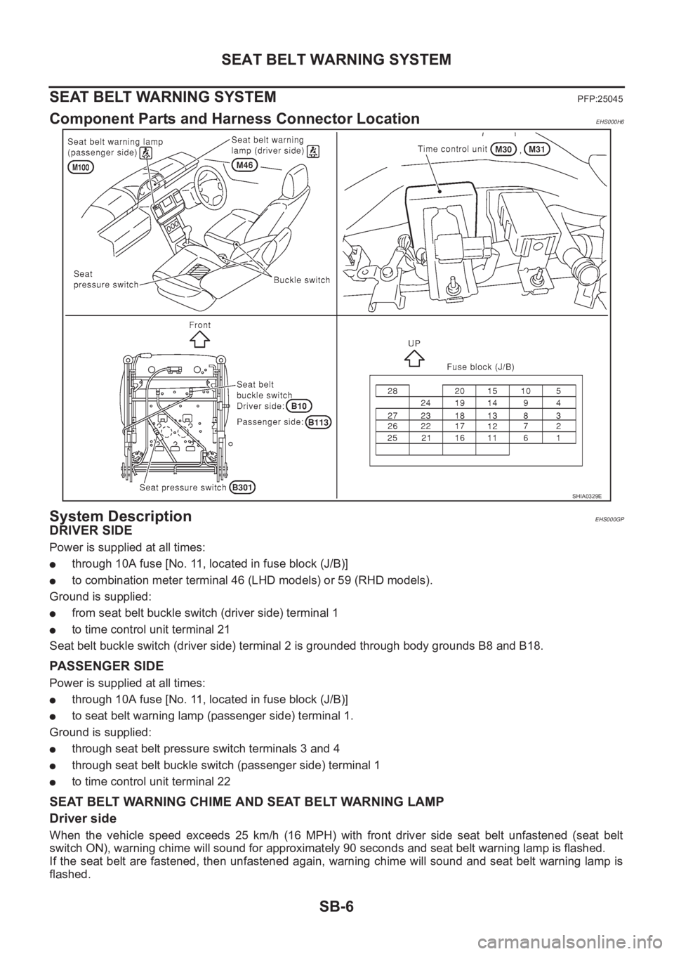
Component Parts and Harness Connector LocationEHS000H6
System DescriptionEHS000GP
DRIVER SIDE
Power is supplied at all times:
●through 10A fuse [No. 11, located in fuse block (J/B)]
●to combination meter terminal 46 (LHD models) or 59 (RHD models).
Ground is supplied:
●from seat belt buckle switch (driver side) terminal 1
●to time control unit terminal 21
Seat belt buckle switch (driver side) terminal 2 is grounded through body grounds B8 and B18.
PASSENGER SIDE
Power is supplied at all times:
●through 10A fuse [No. 11, located in fuse block (J/B)]
●to seat belt warning lamp (passenger side) terminal 1.
Ground is supplied:
●through seat belt pressure switch terminals 3 and 4
●through seat belt buckle switch (passenger side) terminal 1
●to time control unit terminal 22
SEAT BELT WARNING CHIME AND SEAT BELT WARNING LAMP
Driver side
When the vehicle speed exceeds 25 km/h (16 MPH) with front driver side seat belt unfastened (seat belt
switch ON), warning chime will sound for approximately 90 seconds and seat belt warning lamp is flashed.
If the seat belt are fastened, then unfastened again, warning chime will sound and seat belt warning lamp is
flashed.
SHIA0329E
Page 2993 of 3833
SEAT BELT WARNING SYSTEM
SB-11
C
D
E
F
G
I
J
K
L
MA
B
SB
Seat Belt Warning Lamp Inspection (Driver side)EHS000GT
1.FUSE INSPECTION
Check if 10A fuse [No.11, located in fuse block (J/B)] is blown.
OK or NG
OK >> GO TO 2.
NG >> Replace the 10A fuse [No.11, located in fuse block (J/B)].
2.POWER SUPPLY CIRCUIT
1. Disconnect combination meter harness connector.
2. Turn ignition switch “ON”.
3. Check voltage between combination meter harness connector
M46 terminal 46 (LHD models: W/L) or 59 (RHD models: W/L)
and ground.
OK or NG
OK >> GO TO3.
NG >> Repair or replace harness.
3.CHECK SEAT BELT BUCKLE SWITCH GROUND CIRCUIT
1. Connect combination meter.
2. Check continuity between combination meter harness connector
M46 terminal 46 (W/L) and 59 (W/B) (LHD models) or 59 (W/L)
and 48 (W/B) (RHD models)
OK or NG
OK >> GO TO 4.
NG >> Replace combination meter.Battery voltage should exist.
SHIA0303E
Continuity should exist.
PIIA4668E
Page 2994 of 3833
SB-12
SEAT BELT WARNING SYSTEM
4. HARNESS CONTINUITY INSPECTION
1. Turn ignition switch “OFF”.
2. Disconnect time control unit connector and combination meter
connector.
3. Check the following.
LHD models
–Check continuity between combination meter harness connector
M46 terminal 59 (W/B) and time control unit harness connector
M30 terminal 8 (W/B).
–Check continuity between combination meter harness connector
M46 terminal 59 (W/B) and ground.
RHD models
–Check continuity between combination meter harness connector
M46 terminal 48 (W/B) and time control unit harness connector
M30 terminal 8 (W/B).
–Check continuity between combination meter harness connector
M46 terminal 48 (W/B) and ground.
OK or NG
OK >> System is OK.
NG >> Repair or replace harness.Continuity should exist.
Continuity should not exist.
Continuity should exist.
Continuity should not exist.
SHIA0331E
Page 3000 of 3833
SB-18
SEAT BELT WARNING SYSTEM
Vehicle Speed Signal Inspection
EHS000GZ
1. COMBINATION METER CHECK
Check the speed meter in combination meter operates normally.
OK or NG
OK >> GO TO 2.
NG >> Check combination meter system. Refer to DI-12, "
SYMPTOM CHART" (LHD models) or DI-32,
"SYMPTOM CHART" (RHD models).
2. VEHICLE SPEED INPUT SIGNAL INSPECTION
Start the engine, and check the voltage between time control unit harness connector M31 terminal 36 (*).
NOTE:
*: Wire color is different depending on vehicle. Each wire color are as follows:
OK or NG
OK >> System is OK.
NG >> GO TO 3.
Terminal
Vo l ta g e
(+) (–)
36* Ground
Vehicle Wire color
A/T models L/W
M/T models with gasoline engine L/Y
Diesel engine models L/B
SHIA0321EELF1080D
Page 3001 of 3833

SEAT BELT WARNING SYSTEM
SB-19
C
D
E
F
G
I
J
K
L
MA
B
SB
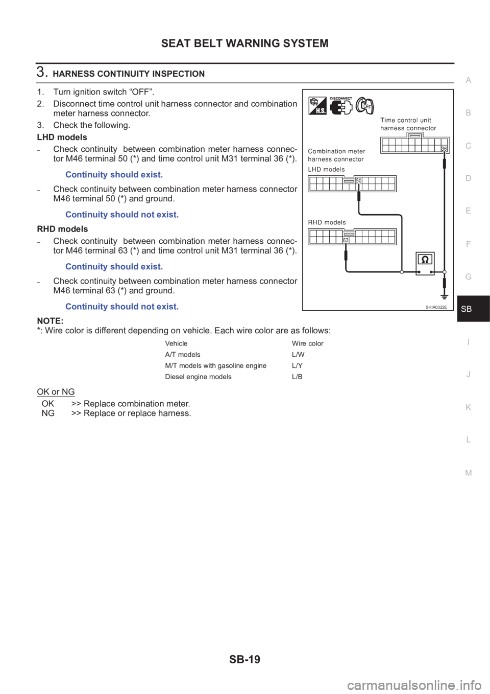
3.HARNESS CONTINUITY INSPECTION
1. Turn ignition switch “OFF”.
2. Disconnect time control unit harness connector and combination
meter harness connector.
3. Check the following.
LHD models
–Check continuity between combination meter harness connec-
tor M46 terminal 50 (*) and time control unit M31 terminal 36 (*).
–Check continuity between combination meter harness connector
M46 terminal 50 (*) and ground.
RHD models
–Check continuity between combination meter harness connec-
tor M46 terminal 63 (*) and time control unit M31 terminal 36 (*).
–Check continuity between combination meter harness connector
M46 terminal 63 (*) and ground.
NOTE:
*: Wire color is different depending on vehicle. Each wire color are as follows:
OK or NG
OK >> Replace combination meter.
NG >> Replace or replace harness.Continuity should exist.
Continuity should not exist.
Continuity should exist.
Continuity should not exist.
Vehicle Wire color
A/T models L/W
M/T models with gasoline engine L/Y
Diesel engine models L/B
SHIA0322E
Page 3030 of 3833
SRS-28
TROUBLE DIAGNOSIS
Trouble Diagnoses: “AIR BAG” Warning Lamp Does Not Turn On
EHS000OC
DIAGNOSTIC PROCEDURE 6
1. CHECK “METER” FUSE
Check the “METER” fuse (No. 11).
Refer to PG-2, "
POWER SUPPLY ROUTING" .
OK or NG
OK >> GO TO 3.
NG >> GO TO 2.
2. CHECK “METER” FUSE AGAIN
Replace meter fuse and turn ignition switch ON.
Is meter fuse blown again?
Yes >> Repair the related harness.
No >>INSPECTION END
3. CHECK HARNESS CONNECTION BETWEEN DIAGNOSIS SENSOR UNIT AND COMBINATION
METER
Disconnect diagnosis sensor unit connector and turn ignition switch “ON”.
●Does “AIR BAG” warning lamp turn on?
Ye s o r N o
Yes >> Replace diagnosis sensor unit.
No >> Check the ground circuit of “AIR BAG” warning lamp.