2001 NISSAN X-TRAIL Combination
[x] Cancel search: CombinationPage 3050 of 3833
SRS-48
COLLISION DIAGNOSIS
For Side Collision
EHS000DG
WHEN THE SIDE AIR BAG IS ACTIVATED IN THE SIDE COLLISION:
1. Replace the following component:
–All parts of front seat back (including front seat back frame) with front side air bag module (on the side on
which front side air bag is activated)
–Diagnosis sensor unit
–Side air bag (Satellite) sensor
2. Check the SRS components and the related parts using the table shown below.
–Replace any SRS components and the related parts showing visible signs of damage (dents, cracks,
deformation).
3. Conduct self-diagnosis using CONSULT-II or “AIR BAG” warning lamp. Refer to SRS-16, "
SRS Operation
Check" . Ensure entire SRS operation properly.
WHEN SRS IS NOT ACTIVATED IN THE SIDE COLLISION:
1. Check the SRS components and the related parts using the table shown below.
–Replace any SRS components and the related parts showing visible signs of damage (dents, cracks,
deformation).
2. Conduct self-diagnosis using CONSULT-II or “AIR BAG” warning lamp. Refer to SRS-16, "
SRS Operation
Check" . Ensure entire SRS operation properly.
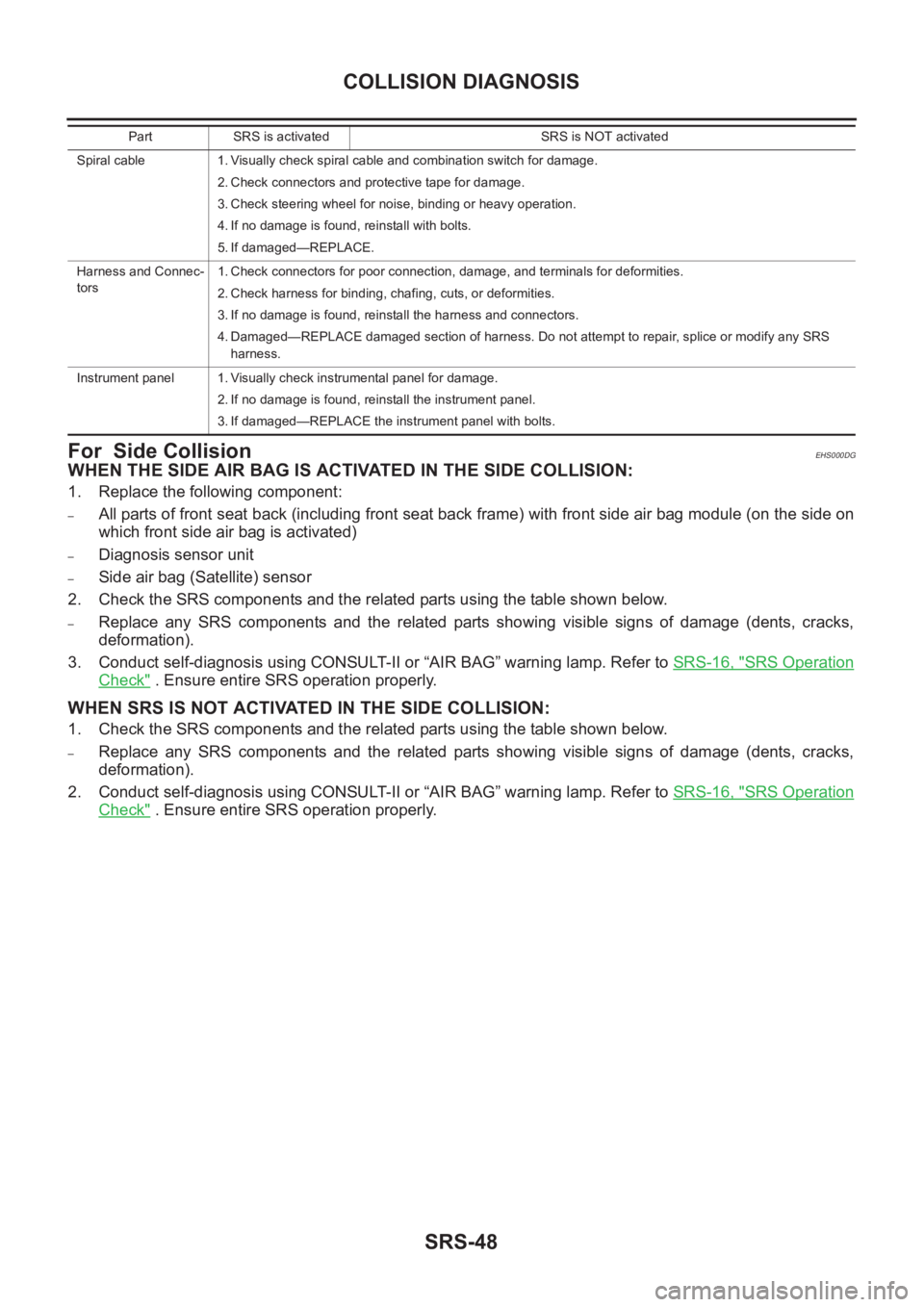
Spiral cable 1. Visually check spiral cable and combination switch for damage.
2. Check connectors and protective tape for damage.
3. Check steering wheel for noise, binding or heavy operation.
4. If no damage is found, reinstall with bolts.
5. If damaged—REPLACE.
Harness and Connec-
tors1. Check connectors for poor connection, damage, and terminals for deformities.
2. Check harness for binding, chafing, cuts, or deformities.
3. If no damage is found, reinstall the harness and connectors.
4. Damaged—REPLACE damaged section of harness. Do not attempt to repair, splice or modify any SRS
harness.
Instrument panel 1. Visually check instrumental panel for damage.
2. If no damage is found, reinstall the instrument panel.
3. If damaged—REPLACE the instrument panel with bolts. Part SRS is activated SRS is NOT activated
Page 3251 of 3833
IP-1
INSTRUMENT PANEL
I BODY
CONTENTS
C
D
E
F
G
H
J
K
L
M
SECTION
A
B
IP
INSTRUMENT PANEL
PRECAUTIONS .......................................................... 2
Precautions for Supplemental Restraint System
(SRS) “AIR BAG” and “SEAT BELT PRE-TEN-
SIONER” .................................................................. 2
Precautions .............................................................. 2
INSTRUMENT PANEL ASSEMBLY ........................... 3
Component Parts Drawing ....................................... 3
Removal and Installation .......................................... 5
TABLE OF WORK ITEM ....................................... 5
FRONT SPEAKER GRILLE .................................. 6
INSTRUMENT FINISHER ..................................... 6
CUP HOLDER ....................................................... 6
CLUSTER LID A ................................................... 6
COMBINATION METER ....................................... 6
POCKET ............................................................... 6
STEERING COLUMN COVER ............................. 6
INSTRUMENT LOWER DRIVER PANEL ............. 7
MIRROR CONTROL SWITCH .............................. 7
GPS ANTENNA .................................................... 7
CLUSTER LID C ................................................... 7CLUSTER LID FINISHER ..................................... 7
AUDIO UNIT AND POCKET ................................. 7
HEATER CONTROL FINISHER ............................ 8
CD AUTO–CHANGER AND POCKET .................. 8
HEATER CONTROLLER ....................................... 8
A/T OR M/T FINISHER ......................................... 8
CONSOLE MASK AND CENTER CONSOLE ....... 8
LOWER INSTRUMENT COVER ........................... 8
INSTRUMENT LOWER CENTER PANEL ............ 8
GLOVE BOX ......................................................... 9
LOWER INSTRUMENT PANEL ............................ 9
GLOVE BOX COVER ............................................ 9
FRONT PASSENGER AIR BAG MODULE ........... 9
INSTRUMENT REINFORCEMENT ....................... 9
INSTRUMENT MASK ............................................ 9
FRONT PILLAR GARNISH ................................... 9
INSTRUMENT PANEL .......................................... 9
Disassembly and Assembly .................................... 10
CONSOLE BOX ASSEMBLY .............................. 10
Page 3254 of 3833
IP-4
INSTRUMENT PANEL ASSEMBLY
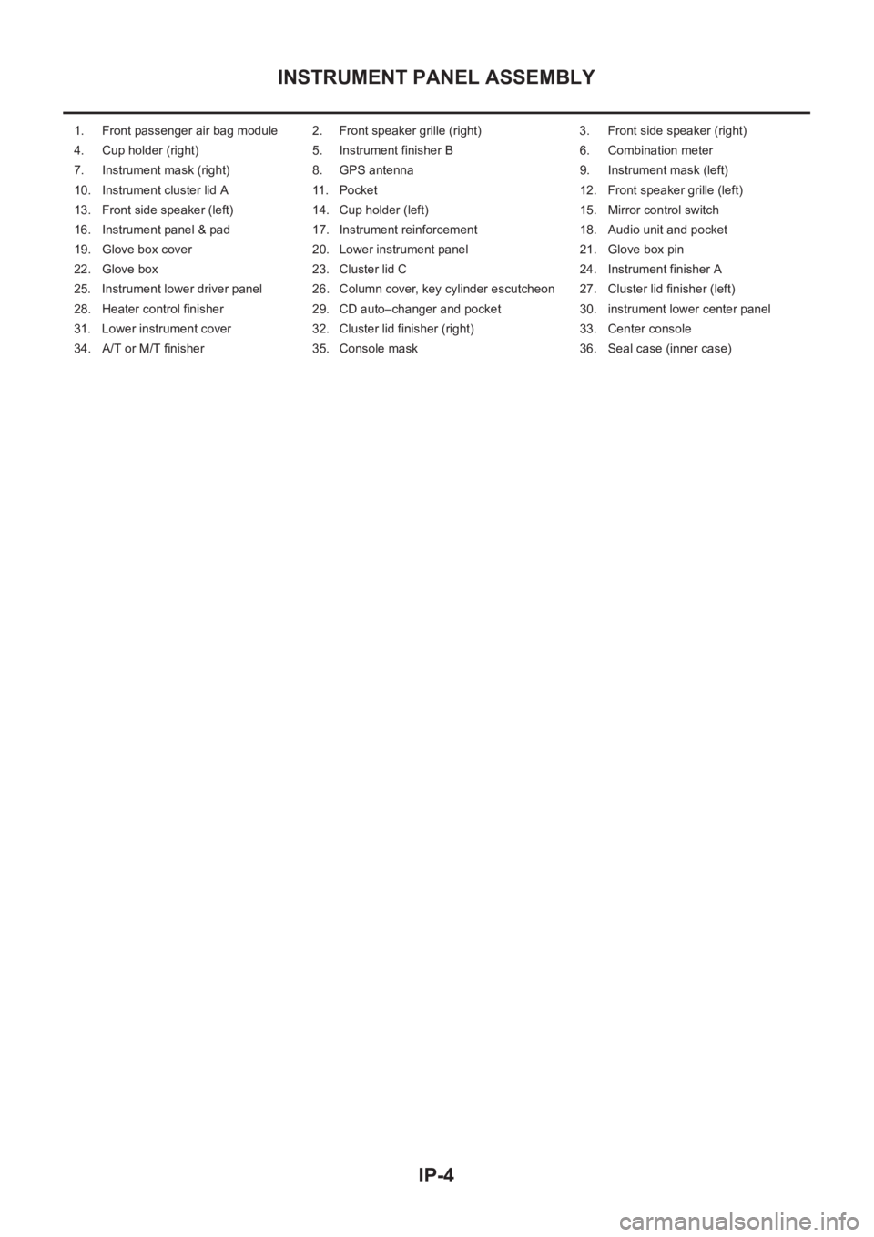
1. Front passenger air bag module 2. Front speaker grille (right) 3. Front side speaker (right)
4. Cup holder (right) 5. Instrument finisher B 6. Combination meter
7. Instrument mask (right) 8. GPS antenna 9. Instrument mask (left)
10. Instrument cluster lid A 11. Pocket 12. Front speaker grille (left)
13. Front side speaker (left) 14. Cup holder (left) 15. Mirror control switch
16. Instrument panel & pad 17. Instrument reinforcement 18. Audio unit and pocket
19. Glove box cover 20. Lower instrument panel 21. Glove box pin
22. Glove box 23. Cluster lid C 24. Instrument finisher A
25. Instrument lower driver panel 26. Column cover, key cylinder escutcheon 27. Cluster lid finisher (left)
28. Heater control finisher 29. CD auto–changer and pocket 30. instrument lower center panel
31. Lower instrument cover 32. Cluster lid finisher (right) 33. Center console
34. A/T or M/T finisher 35. Console mask 36. Seal case (inner case)
Page 3255 of 3833
![NISSAN X-TRAIL 2001 Service Repair Manual INSTRUMENT PANEL ASSEMBLY
IP-5
C
D
E
F
G
H
J
K
L
MA
B
IP
Removal and InstallationEIS000NI
TABLE OF WORK ITEM
[ ]: The number shows the removal order.
ComponentsInstrument
panelCombination
meterNavig NISSAN X-TRAIL 2001 Service Repair Manual INSTRUMENT PANEL ASSEMBLY
IP-5
C
D
E
F
G
H
J
K
L
MA
B
IP
Removal and InstallationEIS000NI
TABLE OF WORK ITEM
[ ]: The number shows the removal order.
ComponentsInstrument
panelCombination
meterNavig](/manual-img/5/57405/w960_57405-3254.png)
INSTRUMENT PANEL ASSEMBLY
IP-5
C
D
E
F
G
H
J
K
L
MA
B
IP
Removal and InstallationEIS000NI
TABLE OF WORK ITEM
[ ]: The number shows the removal order.
ComponentsInstrument
panelCombination
meterNavigation
DisplayAudio
Console
Up Down
Front speaker grille [1]
Instrument finisher A, B [2] [1]
Cup holder [3]
Instrument cluster lid A [4] [2]
Combination meter [5] [3]
Pocket [6]
Key cylinder escutcheon and steer-
ing column cover[7]
Instrument lower driver panel [8]
Mirror control switch [9]
GPS antenna [10]
Cluster lid C [11] [1] [1]
Cluster lid finisher [12] [1] [1]
Audio unit and pocket [13] [2] [2]
Heater control finisher [14] [2]
CD auto–changer and pocket [15] [3]
Heater controller [16]
A/T(M/T,CVT) finisher [17] [2]
Console mask [18] [3]
Center console [19] [4]
Lower instrument cover [20]
instrument lower center panel [21]
Glove box [22]
Lower instrument panel [23]
Glove box cover [24]
Front passenger air bag module [25]
Instrument reinforcement [26]
Instrument mask [27]
Front pillar garnish [28]
Instrument panel [29]
Page 3256 of 3833
IP-6
INSTRUMENT PANEL ASSEMBLY
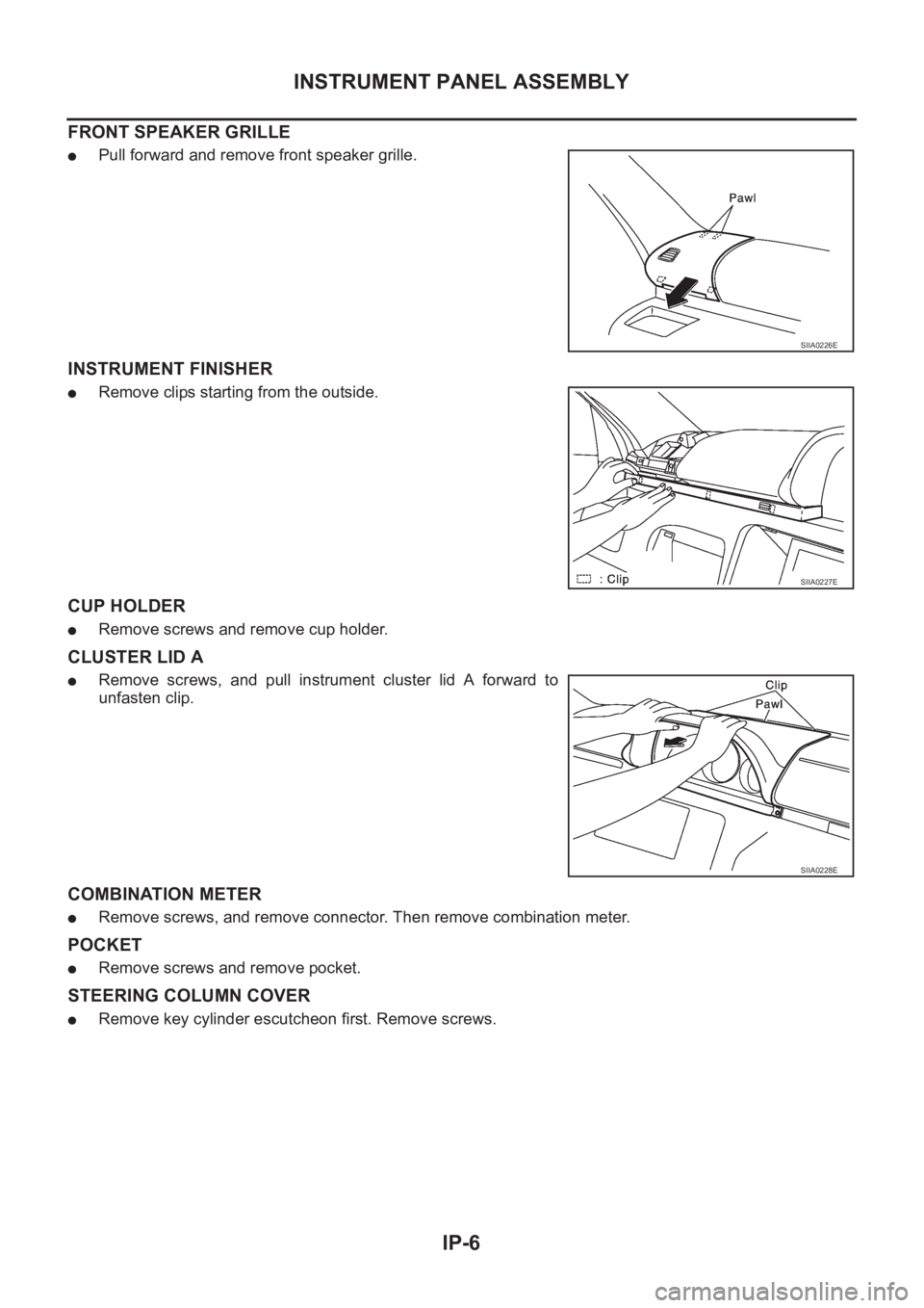
FRONT SPEAKER GRILLE
●Pull forward and remove front speaker grille.
INSTRUMENT FINISHER
●Remove clips starting from the outside.
CUP HOLDER
●Remove screws and remove cup holder.
CLUSTER LID A
●Remove screws, and pull instrument cluster lid A forward to
unfasten clip.
COMBINATION METER
●Remove screws, and remove connector. Then remove combination meter.
POCKET
●Remove screws and remove pocket.
STEERING COLUMN COVER
●Remove key cylinder escutcheon first. Remove screws.
SIIA0226E
SIIA0227E
SIIA0228E
Page 3468 of 3833
SC-12
CHARGING SYSTEM
CHARGING SYSTEM
PFP:00011
System Description EKS00316
The alternator provides DC voltage to operate the vehicle's electrical system and to keep the battery charged.
The voltage output is controlled by the IC regulator.
Power is supplied at all times
●to alternator terminal 4 (S)
●through 10A fuse (No.34, located in the fuse and fusible link box)
●to alternator terminal B
●through 120A (Gasoline engine models) or 100A (Diesel engine models) fusible link (letter A, located in
the fuse and fusible link box).
Terminal B supplies power to charge the battery and operate the vehicle's electrical system. Output voltage is
controlled by the IC regulator at terminal 4 (S) detecting the input voltage. The charging circuit is protected by
the 120A (Gasoline engine models) or 100A (Diesel engine models) link.
The alternator is grounded to the engine block.
With the ignition switch in the ON or START position, power is supplied
●through 10A fuse [No. 11, located in the fuse block (J/B)]
●to combination meter terminal 46 (LHD models) or terminal 59 (RHD models) for the charge warning
lamp.
Ground is supplied with power and ground supplied
●to terminal 64 (LHD models) or terminal 54 ( RHD models) of the combination meter
●through terminal 3 (L) of the alternator
●to terminal E of the alternator
●through body ground E30.
The charge warning lamp will illuminate. When the alternator is providing sufficient voltage with the engine
running, the ground is opened and the charge warning lamp will go off.
If the charge warning lamp illuminates with the engine running, a malfunction is indicated.
Page 3491 of 3833
LT-1
LIGHTING SYSTEM
K ELECTRICAL
CONTENTS
C
D
E
F
G
H
I
J
L
M
SECTION
A
B
LT
LIGHTING SYSTEM
PRECAUTION ............................................................ 3
Precautions for Supplemental Restraint System
(SRS) “AIR BAG” and “SEAT BELT PRE-TEN-
SIONER” .................................................................. 3
Precaution ................................................................ 3
Wiring Diagrams and Trouble Diagnosis .................. 3
HEADLAMP ................................................................ 4
System Description .................................................. 4
DESCRIPTION ...................................................... 4
LOW BEAM OPERATION ..................................... 4
HIGH BEAM OPERATION/FLASH-TO-PASS
OPERATION ......................................................... 4
Wiring Diagram — H/LAMP — ................................. 5
Trouble Diagnoses ................................................... 6
Aiming Adjustment ................................................... 6
LOW BEAM ........................................................... 7
Bulb Replacement .................................................... 8
HEAD LAMP ......................................................... 8
CLEARANCE LAMP ............................................. 8
Removal and Installation .......................................... 8
REMOVAL ............................................................. 8
INSTALLATION ..................................................... 8
HEADLAMP - DAYTIME LIGHT SYSTEM - ............... 9
System Description .................................................. 9
DESCRIPTION ...................................................... 9
HEADLAMP OPERATION (DAYTIME LIGHT
CANCEL OPERATION) ........................................ 9
DAYTIME LIGHT OPERATION ............................. 9
Schematic .............................................................. 10
Wiring Diagram -DTRL- ........................................... 11
Trouble Diagnoses ................................................. 14
DAYTIME LIGHT CONTROL UNIT INSPECTION
TABLE ................................................................. 14
Bulb Replacement .................................................. 14
Aiming Adjustment ................................................. 14
HEADLAMP AIMING CONTROL ............................. 15
Wiring Diagram -H/AIM- ......................................... 15
Removal and Installation ........................................ 16
Switch Circuit Inspection ........................................ 16
TURN SIGNAL AND HAZARD WARNING LAMPS ... 17System Description ................................................. 17
TURN SIGNAL OPERATION .............................. 17
HAZARD LAMP OPERATION ............................. 17
Wiring Diagram — TURN — ................................... 19
Trouble Diagnoses ................................................. 21
Electrical Components Inspection .......................... 21
COMBINATION FLASHER UNIT CHECK ........
... 21
Bulb Replacement .................................................. 22
FRONT TURN SIGNAL LAMP ............................ 22
SIDE TURN SIGNAL LAMP ................................ 22
REAR TURN SIGNAL LAMP .............................. 22
Removal and Installation for Front Turn Signal Lamp ... 22
REMOVAL ........................................................... 22
INSTALLATION ................................................... 22
Removal and Installation for Side Turn Signal Lamp ... 23
Removal and Installation for Rear Turn Signal Lamp ... 23
LIGHTING AND TURN SIGNAL SWITCH ................ 24
Removal and Installation ........................................ 24
Switch Circuit Inspection ........................................ 24
HAZARD SWITCH .................................................... 25
Removal and Installation ........................................ 25
REMOVAL ........................................................... 25
INSTALLATION ................................................... 25
STOP LAMP .............................................................. 26
Wiring Diagram — STOP/L — ................................ 26
Bulb Replacement .................................................. 27
STOP LAMP ........................................................ 27
HIGH-MOUNTED STOP LAMP ........................... 27
Removal and Installation ........................................ 27
STOP LAMP ........................................................ 27
HIGH-MOUNTED STOP LAMP ........................... 27
BACK-UP LAMP ....................................................... 28
Wiring Diagram — BACK/L — ................................ 28
Bulb Replacement .................................................. 29
Removal and Installation ........................................ 29
PARKING, LICENSE PLATE AND TAIL LAMPS ..... 30
Wiring Diagram — TAIL/L — .................................. 30
Bulb Replacement .................................................. 32
PARKING AND TAIL LAMPS .............................. 32
Page 3492 of 3833
LT-2
LICENSE PLATE LAMP ...................................... 32
Removal and Installation ........................................ 32
PARKING AND TAIL LAMPS ............................... 32
LICENSE PLATE LAMP ...................................... 32
FRONT FOG LAMP .................................................. 33
System Description ................................................. 33
DESCRIPTION .................................................... 33
FOG LAMP OPERATION .................................... 33
Wiring Diagram — F/FOG — .................................. 34
Aiming Adjustment .................................................. 35
Bulb Replacement .................................................. 36
Removal and Installation ........................................ 36
REMOVAL ........................................................... 36
INSTALLATION .................................................... 36
REAR FOG LAMP .................................................. ... 37
Wiring Diagram -R/FOG-/Without Front Fog Lamp ... 37
Wiring Diagram -R/FOG-/With Front Fog Lamp ..... 38
Bulb Replacement .................................................. 39
Removal and Installation ........................................ 39
REMOVAL ........................................................... 39
INSTALLATION .................................................... 39
CLEARANCE LAMP/TAIL LAMP ............................. 40
Bulb Replacement (Clearance Lamp) .................... 40
Bulb Replacement (Taillamp) .................................. 40
Removal and Installation of Clearance Lamp ......... 40
Removal and Installation of Taillamp ...................... 40
HIGH-MOUNTED STOP LAMP ................................ 41
Bulb Replacement .................................................. 41
Removal and Installation ........................................ 41
REAR COMBINATION LAMP ................................... 42
Wiring Diagram —STOP/L— .................................. 42
Bulb Replacement .................................................. 43
Removal and Installation ........................................ 43
REMOVAL ........................................................... 43
INSTALLATION .................................................... 43COMBINATION SWITCH .......................................... 44
Removal and Installation ......................................... 44
Switch Circuit Inspection ...................................... ... 44
ILLUMINATION .......................................................... 45
System Description ................................................. 45
Schematic ............................................................... 46
Wiring Diagram -ILL-/LHD MODELS ...................... 47
Wiring Diagram -ILL-/RHD MODELS ...................... 51
INTERIOR ROOM LAMP .......................................
... 55
System Description ................................................. 55
POWER SUPPLY AND GROUND ....................... 55
SWITCH OPERATION ......................................... 55
INTERIOR ROOM LAMP TIMER OPERATION ... 56
ON-OFF CONTROL ............................................. 56
Wiring Diagram -ROOM/L- ...................................... 57
Interior Room Lamp Timer Does Not Operate ........ 59
Interior Room Lamp Timer Does Not Cancel .......... 62
Bulb Replacement ................................................... 64
INTERIOR ROOM LAMP ..................................... 64
LUGGAGE ROOM LAMP .................................... 64
Removal and Installation ......................................... 64
INTERIOR ROOM LAMP ..................................... 64
LUGGAGE ROOM LAMP .................................... 64
SPOT LAMPS ............................................................ 65
Wiring Diagram -INT/L- ........................................... 65
Bulb Replacement ................................................... 66
SPOT LAMP (WITHOUT SUNROOF) ................. 66
SPOT LAMP (WITH SUNROOF) ......................... 66
Removal and Installation ......................................... 66
SPOT LAMP (WITHOUT SUNROOF) ................. 66
SPOT LAMP (WITH SUNROOF) ......................... 66
BULB SPECIFICATIONS .......................................... 67
Headlamp ................................................................ 67
Exterior Lamp .......................................................... 67
Interior Lamp/Illumination ........................................ 67