Page 3566 of 3833
DI-8
COMBINATION METERS (LHD MODELS)
Wiring Diagram — METER —
EKS002ZB
TKWA0086E
Page 3567 of 3833
COMBINATION METERS (LHD MODELS)
DI-9
C
D
E
F
G
H
I
J
L
MA
B
DI
TKWA0087E
Page 3568 of 3833
DI-10
COMBINATION METERS (LHD MODELS)
Meter/Gauge Operation and Odo/Trip Meter Segment Check in Diagnosis Mode
EKS002ZC
DIAGNOSIS FUNCTION
●Odo/trip meter segment can be checked in diagnosis mode.
●Meters/gauges can be checked in diagnosis mode.
HOW TO ALTERNATE DIAGNOSIS MODE
1. Turn ignition switch to ON and change odo/trip meter to “TRIP A” or “TRIP B”.
2. Turn ignition switch to OFF.
3. Turn ignition switch to ON when pushing odo/trip meter switch.
4. Confirm that trip meter indicates “000.0”.
5. Push odo/trip meter switch more than three times within 5 seconds.
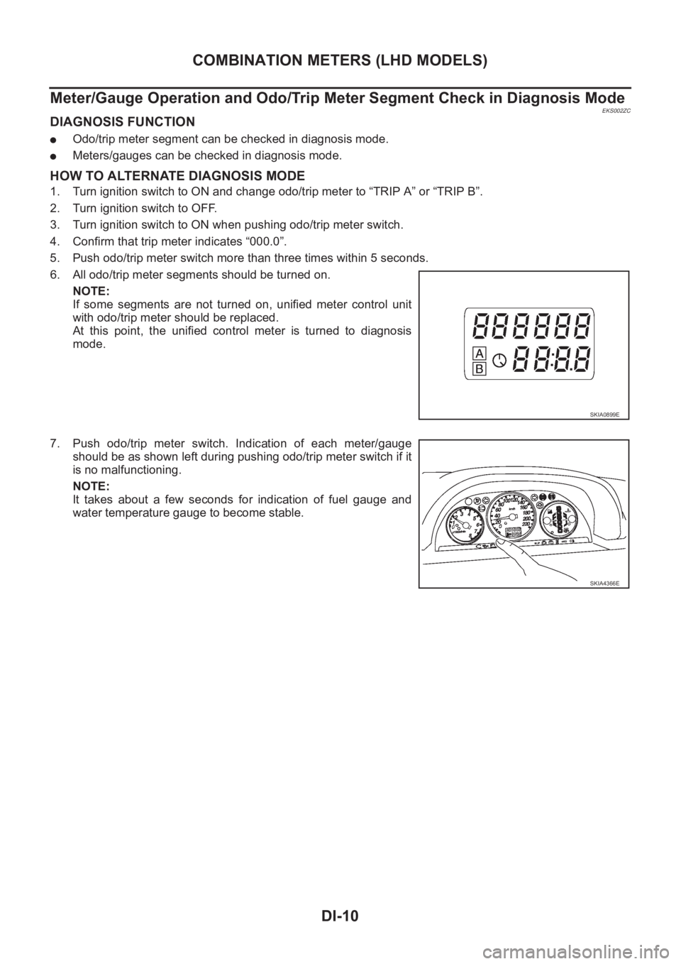
6. All odo/trip meter segments should be turned on.
NOTE:
If some segments are not turned on, unified meter control unit
with odo/trip meter should be replaced.
At this point, the unified control meter is turned to diagnosis
mode.
7. Push odo/trip meter switch. Indication of each meter/gauge
should be as shown left during pushing odo/trip meter switch if it
is no malfunctioning.
NOTE:
It takes about a few seconds for indication of fuel gauge and
water temperature gauge to become stable.
SKIA0899E
SKIA4366E
Page 3569 of 3833
COMBINATION METERS (LHD MODELS)
DI-11
C
D
E
F
G
H
I
J
L
MA
B
DI
Trouble DiagnosesEKS002ZD
PRELIMINARY CHECK
1.CHECK WARNING LAMPS
1. Turn ignition switch ON.
2. Warning lamps should illuminate (seat belt warning or door warning etc.).
Do warning lamps illuminate?
Ye s > > G O T O 2 .
No >> Power supply and ground circuit check. Refer to DI-13, "
Power Supply and Ground Circuit Check"
.
2.CHECK DIAGNOSIS MODE OPERATION
Preform diagnosis mode. Refer to DI-10, "
Meter/Gauge Operation and Odo/Trip Meter Segment Check in
Diagnosis Mode" .
Can diagnosis mode be activated?
Ye s > > G O T O 3 .
No >> Power supply and ground circuit check. Refer to DI-13, "
Power Supply and Ground Circuit Check"
3.SEGMENTS CHECK
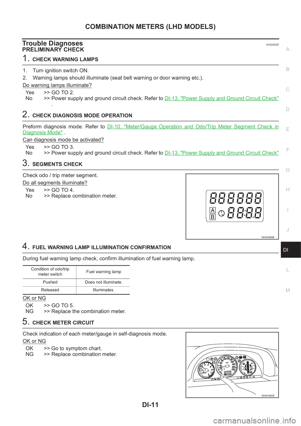
Check odo / trip meter segment.
Do all segments illuminate?
Ye s > > G O T O 4 .
No >> Replace combination meter.
4.FUEL WARNING LAMP ILLUMINATION CONFIRMATION
During fuel warning lamp check, confirm illumination of fuel warning lamp.
OK or NG
OK >> GO TO 5.
NG >> Replace the combination meter.
5.CHECK METER CIRCUIT
Check indication of each meter/gauge in self-diagnosis mode.
OK or NG
OK >> Go to symptom chart.
NG >> Replace combination meter.
SKIA0899E
Condition of odo/trip
meter switchFuel warning lamp
Pushed Does not illuminate.
Released Illuminates.
SKIA4366E
Page 3570 of 3833
DI-12
COMBINATION METERS (LHD MODELS)
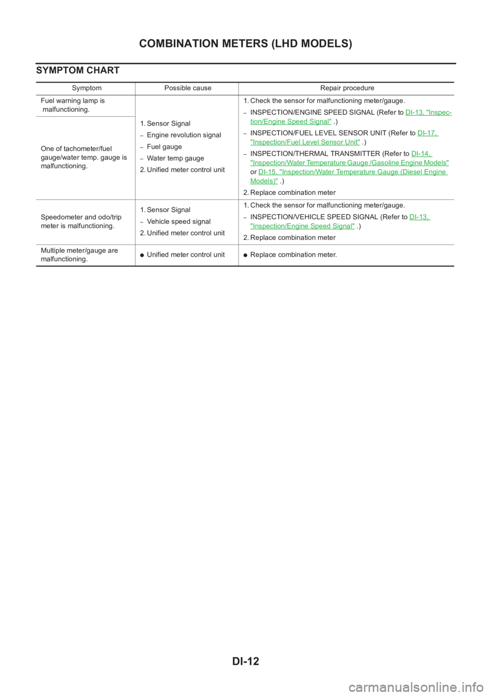
SYMPTOM CHART
Symptom Possible cause Repair procedure
Fuel warning lamp is
malfunctioning.
1. Sensor Signal
–Engine revolution signal
–Fuel gauge
–Water temp gauge
2. Unified meter control unit 1. Check the sensor for malfunctioning meter/gauge.
–INSPECTION/ENGINE SPEED SIGNAL (Refer to DI-13, "Inspec-
tion/Engine Speed Signal" .)
–INSPECTION/FUEL LEVEL SENSOR UNIT (Refer to DI-17,
"Inspection/Fuel Level Sensor Unit" .)
–INSPECTION/THERMAL TRANSMITTER (Refer to DI-14,
"Inspection/Water Temperature Gauge /Gasoline Engine Models"
or DI-15, "Inspection/Water Temperature Gauge (Diesel Engine
Models)" .)
2. Replace combination meter One of tachometer/fuel
gauge/water temp. gauge is
malfunctioning.
Speedometer and odo/trip
meter is malfunctioning.1. Sensor Signal
–Vehicle speed signal
2. Unified meter control unit 1. Check the sensor for malfunctioning meter/gauge.–INSPECTION/VEHICLE SPEED SIGNAL (Refer to DI-13,
"Inspection/Engine Speed Signal" .)
2. Replace combination meter
Multiple meter/gauge are
malfunctioning.
●Unified meter control unit●Replace combination meter.
Page 3571 of 3833
COMBINATION METERS (LHD MODELS)
DI-13
C
D
E
F
G
H
I
J
L
MA
B
DI
Power Supply and Ground Circuit CheckEKS002ZE
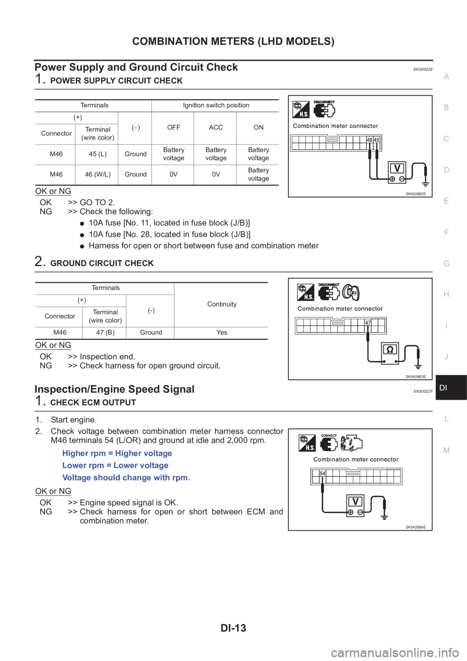
1.POWER SUPPLY CIRCUIT CHECK
OK or NG
OK >> GO TO 2.
NG >> Check the following:
●10A fuse [No. 11, located in fuse block (J/B)]
●10A fuse [No. 28, located in fuse block (J/B)]
●Harness for open or short between fuse and combination meter
2.GROUND CIRCUIT CHECK
OK or NG
OK >> Inspection end.
NG >> Check harness for open ground circuit.
Inspection/Engine Speed SignalEKS002ZF
1.CHECK ECM OUTPUT
1. Start engine.
2. Check voltage between combination meter harness connector
M46 terminals 54 (L/OR) and ground at idle and 2,000 rpm.
OK or NG
OK >> Engine speed signal is OK.
NG >> Check harness for open or short between ECM and
combination meter.
Terminals Ignition switch position
(+)
(−)OFF ACC ON
ConnectorTerminal
(wire color)
M46 45 (L) GroundBattery
voltageBattery
voltageBattery
voltage
M46 46 (W/L) Ground 0V 0VBattery
voltage
SKIA0982E
Terminals
Continuity (+)
(-)
ConnectorTerminal
(wire color)
M46 47 (B) Ground Yes
SKIA0983E
Higher rpm = Higher voltage
Lower rpm = Lower voltage
Voltage should change with rpm.
SKIA0984E
Page 3572 of 3833
DI-14
COMBINATION METERS (LHD MODELS)
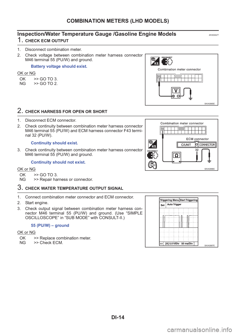
Inspection/Water Temperature Gauge /Gasoline Engine Models
EKS002ZT
1. CHECK ECM OUTPUT
1. Disconnect combination meter.
2. Check voltage between combination meter harness connector
M46 terminal 55 (PU/W) and ground.
OK or NG
OK >> GO TO 3.
NG >> GO TO 2.
2. CHECK HARNESS FOR OPEN OR SHORT
1. Disconnect ECM connector.
2. Check continuity between combination meter harness connector
M46 terminal 55 (PU/W) and ECM harness connector F43 termi-
nal 32 (PU/W).
3. Check continuity between combination meter harness connector
M46 terminal 55 (PU/W) and ground.
OK or NG
OK >> GO TO 3.
NG >> Repair harness or connector.
3. CHECK WATER TEMPERATURE OUTPUT SIGNAL
1. Connect combination meter connector and ECM connector.
2. Start engine.
3. Check output signal between combination meter harness con-
nector M46 terminal 55 (PU/W) and ground. (Use “SIMPLE
OSCILLOSCOPE” in “SUB MODE” with CONSULT-II.)
OK or NG
OK >> Replace combination meter.
NG >> Check ECM.Battery voltage should exist.
SKIA0985E
Continuity should exist.
Continuity should not exist.
SKIA0986E
55 (PU/W) – ground
SKIA0987E
Page 3573 of 3833
COMBINATION METERS (LHD MODELS)
DI-15
C
D
E
F
G
H
I
J
L
MA
B
DI
Inspection/Water Temperature Gauge (Diesel Engine Models)EKS002ZG
1.CHECK THERMAL TRANSMITTER
Refer to DI-22, "
THERMAL TRANSMITTER CHECK" .
OK or NG
OK >> GO TO 2.
NG >> Replace thermal transmitter.
2.CHECK HARNESS FOR OPEN OR SHORT
1. Disconnect combination meter connector and thermal transmit-
ter connector.
2. Check continuity between combination meter harness connector
M46 terminal 55 (PU/W) and thermal transmitter harness con-
nector F23 terminal 1 (PU/W).
3. Check continuity between combination meter harness connector
M46 terminal 55 (PU/W) and ground.
OK or NG
OK >> Thermal transmitter is OK.
NG >> Replace harness or connector.Continuity should exist.
Continuity should not exist.
SKIA0988E