2001 NISSAN X-TRAIL Combination
[x] Cancel search: CombinationPage 3632 of 3833
WW-4
FRONT WIPER AND WASHER SYSTEM
FRONT WIPER AND WASHER SYSTEM
PFP:28810
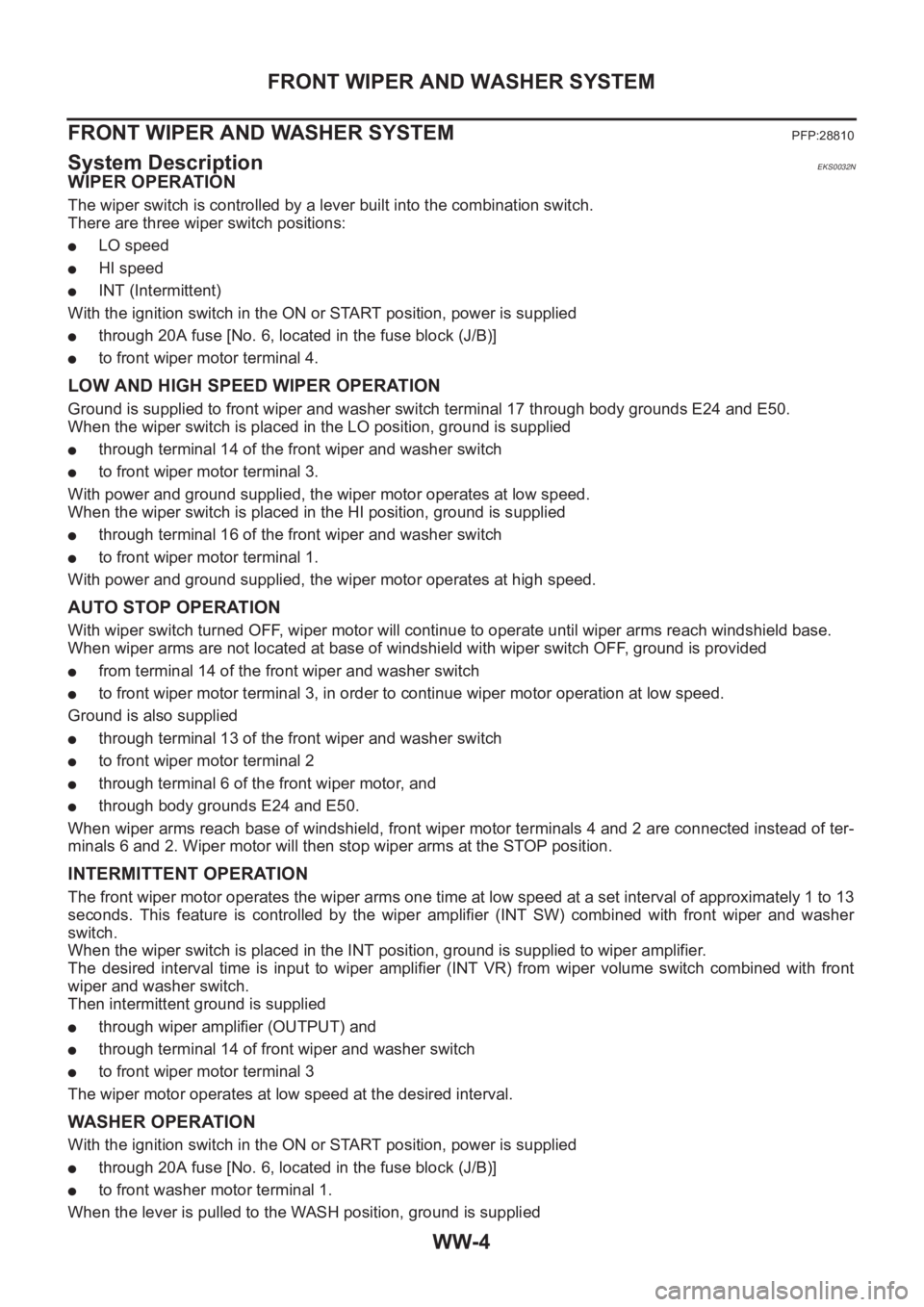
System DescriptionEKS0032N
WIPER OPERATION
The wiper switch is controlled by a lever built into the combination switch.
There are three wiper switch positions:
●LO speed
●HI speed
●INT (Intermittent)
With the ignition switch in the ON or START position, power is supplied
●through 20A fuse [No. 6, located in the fuse block (J/B)]
●to front wiper motor terminal 4.
LOW AND HIGH SPEED WIPER OPERATION
Ground is supplied to front wiper and washer switch terminal 17 through body grounds E24 and E50.
When the wiper switch is placed in the LO position, ground is supplied
●through terminal 14 of the front wiper and washer switch
●to front wiper motor terminal 3.
With power and ground supplied, the wiper motor operates at low speed.
When the wiper switch is placed in the HI position, ground is supplied
●through terminal 16 of the front wiper and washer switch
●to front wiper motor terminal 1.
With power and ground supplied, the wiper motor operates at high speed.
AUTO STOP OPERATION
With wiper switch turned OFF, wiper motor will continue to operate until wiper arms reach windshield base.
When wiper arms are not located at base of windshield with wiper switch OFF, ground is provided
●from terminal 14 of the front wiper and washer switch
●to front wiper motor terminal 3, in order to continue wiper motor operation at low speed.
Ground is also supplied
●through terminal 13 of the front wiper and washer switch
●to front wiper motor terminal 2
●through terminal 6 of the front wiper motor, and
●through body grounds E24 and E50.
When wiper arms reach base of windshield, front wiper motor terminals 4 and 2 are connected instead of ter-
minals 6 and 2. Wiper motor will then stop wiper arms at the STOP position.
INTERMITTENT OPERATION
The front wiper motor operates the wiper arms one time at low speed at a set interval of approximately 1 to 13
seconds. This feature is controlled by the wiper amplifier (INT SW) combined with front wiper and washer
switch.
When the wiper switch is placed in the INT position, ground is supplied to wiper amplifier.
The desired interval time is input to wiper amplifier (INT VR) from wiper volume switch combined with front
wiper and washer switch.
Then intermittent ground is supplied
●through wiper amplifier (OUTPUT) and
●through terminal 14 of front wiper and washer switch
●to front wiper motor terminal 3
The wiper motor operates at low speed at the desired interval.
WASHER OPERATION
With the ignition switch in the ON or START position, power is supplied
●through 20A fuse [No. 6, located in the fuse block (J/B)]
●to front washer motor terminal 1.
When the lever is pulled to the WASH position, ground is supplied
Page 3635 of 3833
FRONT WIPER AND WASHER SYSTEM
WW-7
C
D
E
F
G
H
I
J
L
MA
B
WW
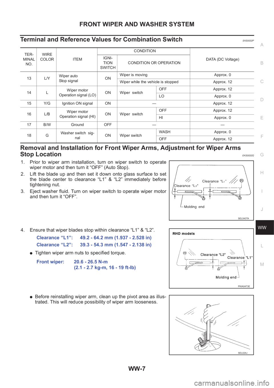
Terminal and Reference Values for Combination SwitchEKS0032P
Removal and Installation for Front Wiper Arms, Adjustment for Wiper Arms
Stop Location
EKS0032Q
1. Prior to wiper arm installation, turn on wiper switch to operate
wiper motor and then turn it “OFF” (Auto Stop).
2. Lift the blade up and then set it down onto glass surface to set
the blade center to clearance “L1” & “L2” immediately before
tightening nut.
3. Eject washer fluid. Turn on wiper switch to operate wiper motor
and then turn it “OFF”.
4. Ensure that wiper blades stop within clearance “L1” & “L2”.
●Tighten wiper arm nuts to specified torque.
●Before reinstalling wiper arm, clean up the pivot area as illus-
trated. This will reduce possibility of wiper arm looseness.
TER-
MINAL
NO.WIRE
COLOR ITEM CONDITION
DATA (DC Voltage) IGNI-
TION
SWITCHCONDITION OR OPERATION
13 L/YWiper auto
Stop signalONWiper is moving Approx. 0
Wiper while the vehicle is stopped Approx. 12
14 LWiper motor
Operation signal (LO)ON Wiper switchOFF Approx. 12
LO Approx. 0
15 Y/G Ignition ON signal ON — Approx. 12
16 L/BWiper motor
Operation signal (HI)ON Wiper switchOFF Approx. 12
HI Approx. 0
17 B/W Ground OFF — —
18 GWasher switch sig-
nalON Wiper switchWASH Approx. 0
OFF Approx. 12
SEL543TA
Clearance “L1”: 49.2 - 64.2 mm (1.937 - 2.528 in)
Clearance “L2”: 39.3 - 54.3 mm (1.547 - 2.138 in)
Front wiper: 20.6 - 26.5 N-m
(2.1 - 2.7 kg-m, 16 - 19 ft-lb)
PKIA0473E
SEL024J
Page 3643 of 3833
REAR WIPER AND WASHER SYSTEM
WW-15
C
D
E
F
G
H
I
J
L
MA
B
WW
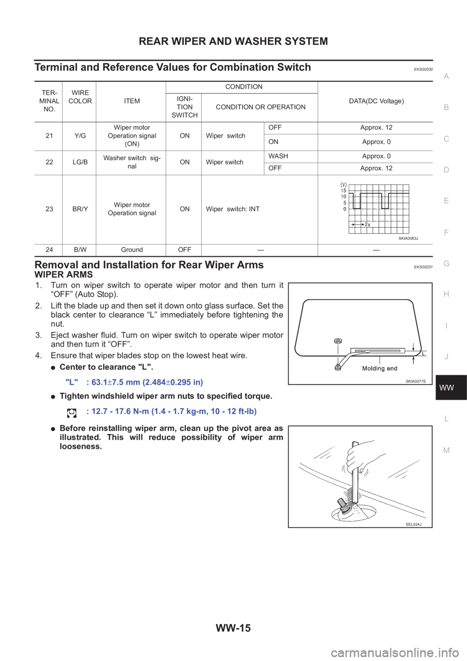
Terminal and Reference Values for Combination SwitchEKS00330
Removal and Installation for Rear Wiper Arms EKS00331
WIPER ARMS
1. Turn on wiper switch to operate wiper motor and then turn it
“OFF” (Auto Stop).
2. Lift the blade up and then set it down onto glass surface. Set the
black center to clearance “L” immediately before tightening the
nut.
3. Eject washer fluid. Turn on wiper switch to operate wiper motor
and then turn it “OFF”.
4. Ensure that wiper blades stop on the lowest heat wire.
●Center to clearance "L".
●Tighten windshield wiper arm nuts to specified torque.
●Before reinstalling wiper arm, clean up the pivot area as
illustrated. This will reduce possibility of wiper arm
looseness.
TER-
MINAL
NO.WIRE
COLOR ITEM CONDITION
DATA(DC Voltage) IGNI-
TION
SWITCHCONDITION OR OPERATION
21 Y/GWiper motor
Operation signal
(ON)ON Wiper switchOFF Approx. 12
ON Approx. 0
22 LG/BWasher switch sig-
nalON Wiper switchWASH Approx. 0
OFF Approx. 12
23 BR/YWiper motor
Operation signalON Wiper switch: INT
24 B/W Ground OFF — —
SKIA0083J
"L" : 63.1±7.5 mm (2.484±0.295 in)
: 12.7 - 17.6 N-m (1.4 - 1.7 kg-m, 10 - 12 ft-lb)SKIA0077E
SEL024J
Page 3659 of 3833
TIME CONTROL UNIT
BCS-3
C
D
E
F
G
H
I
J
L
MA
B
BCS
TIME CONTROL UNITPFP:28491
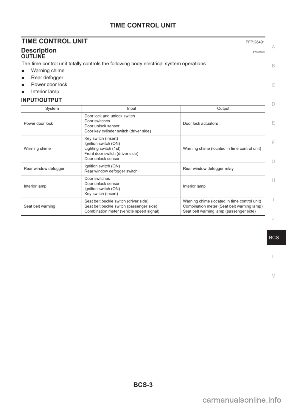
DescriptionEKS002ZU
OUTLINE
The time control unit totally controls the following body electrical system operations.
●Warning chime
●Rear defogger
●Power door lock
●Interior lamp
INPUT/OUTPUT
System Input Output
Power door lockDoor lock and unlock switch
Door switches
Door unlock sensor
Door key cylinder switch (driver side)Door lock actuators
Warning chimeKey switch (Insert)
Ignition switch (ON)
Lighting switch (1st)
Front door switch (driver side)
Door unlock sensorWarning chime (located in time control unit)
Rear window defoggerIgnition switch (ON)
Rear window defogger switchRear window defogger relay
Interior lampDoor switches
Door unlock sensor
Ignition switch (ON)
Key switch (Insert)Interior lamp
Seat belt warningSeat belt buckle switch (driver side)
Seat belt buckle switch (passenger side)
Combination meter (vehicle speed signal)Warning chime (located in time control unit)
Combination meter (Seat belt warning lamp)
Seat belt warning lamp (passenger side)
Page 3661 of 3833
TIME CONTROL UNIT
BCS-5
C
D
E
F
G
H
I
J
L
MA
B
BCS
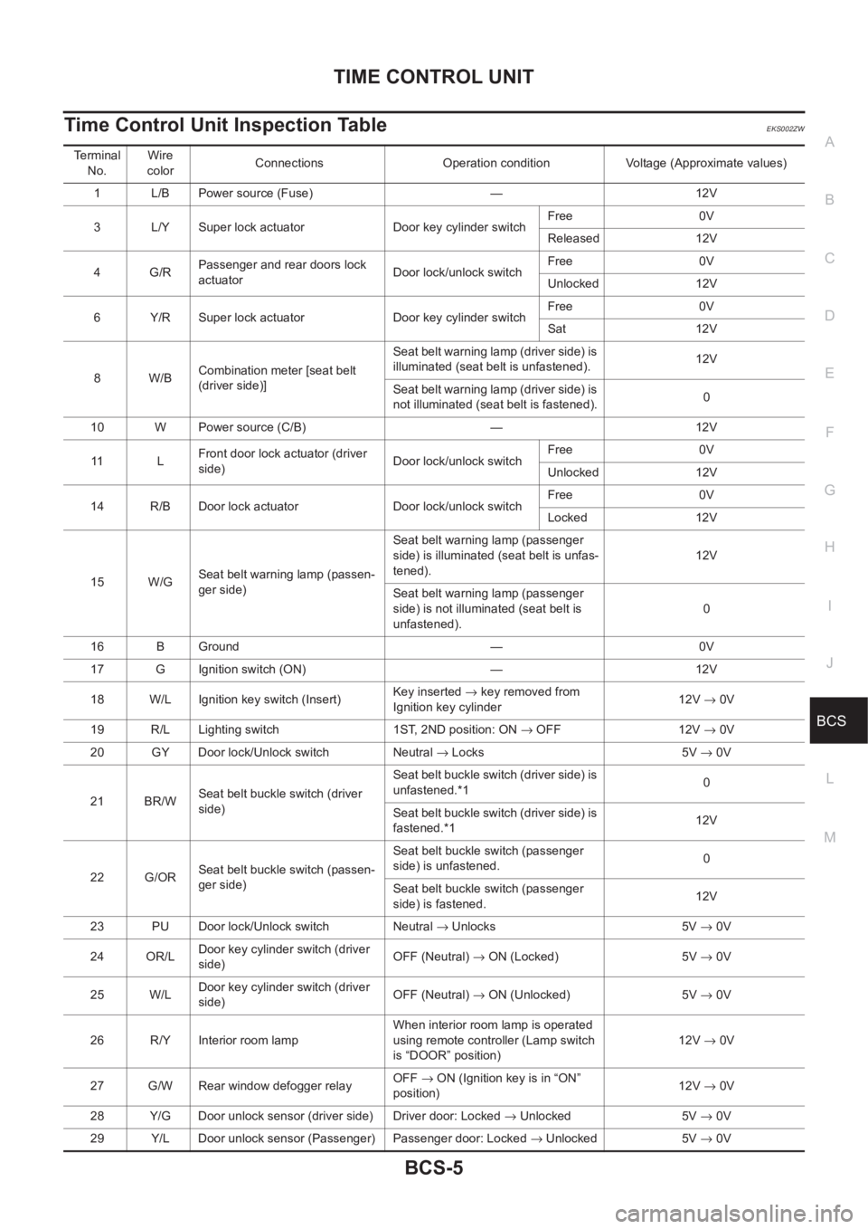
Time Control Unit Inspection TableEKS002ZW
Terminal
No.Wire
colorConnections Operation condition Voltage (Approximate values)
1 L/B Power source (Fuse) — 12V
3 L/Y Super lock actuator Door key cylinder switchFree 0V
Released 12V
4G/RPassenger and rear doors lock
actuatorDoor lock/unlock switchFree 0V
Unlocked 12V
6 Y/R Super lock actuator Door key cylinder switchFree 0V
Sat 12V
8W/BCombination meter [seat belt
(driver side)]Seat belt warning lamp (driver side) is
illuminated (seat belt is unfastened).12V
Seat belt warning lamp (driver side) is
not illuminated (seat belt is fastened).0
10 W Power source (C/B) — 12V
11 LFront door lock actuator (driver
side)Door lock/unlock switchFree 0V
Unlocked 12V
14 R/B Door lock actuator Door lock/unlock switchFree 0V
Locked 12V
15 W/GSeat belt warning lamp (passen-
ger side)Seat belt warning lamp (passenger
side) is illuminated (seat belt is unfas-
tened).12V
Seat belt warning lamp (passenger
side) is not illuminated (seat belt is
unfastened).0
16 B Ground — 0V
17 G Ignition switch (ON) — 12V
18 W/L Ignition key switch (Insert)Key inserted → key removed from
Ignition key cylinder12V → 0V
19 R/L Lighting switch 1ST, 2ND position: ON → OFF 12V → 0V
20 GY Door lock/Unlock switch Neutral → Locks 5V → 0V
21 BR/WSeat belt buckle switch (driver
side)Seat be lt buckle switch (d river side) is
unfastened.*10
Seat be lt buckle switch (d river side) is
fastened.*112V
22 G/ORSeat belt buckle switch (passen-
ger side)Seat belt buckle switch (passenger
side) is unfastened.0
Seat belt buckle switch (passenger
side) is fastened.12V
23 PU Door lock/Unlock switch Neutral → Unlocks 5V → 0V
24 OR/LDoor key cylinder switch (driver
side)OFF (Neutral) → ON (Locked) 5V → 0V
25 W/LDoor key cylinder switch (driver
side)OFF (Neutral) → ON (Unlocked) 5V → 0V
26 R/Y Interior room lampWhen interior room lamp is operated
using remote controller (Lamp switch
is “DOOR” position)12V → 0V
27 G/W Rear window defogger relayOFF→ ON (Ignition key is in “ON”
position)12V → 0V
28 Y/G Door unlock sensor (driver side) Driver door: Locked → Unlocked 5V → 0V
29 Y/L Door unlock sensor (Passenger) Passenger door: Locked → Unlocked 5V → 0V
Page 3662 of 3833
BCS-6
TIME CONTROL UNIT
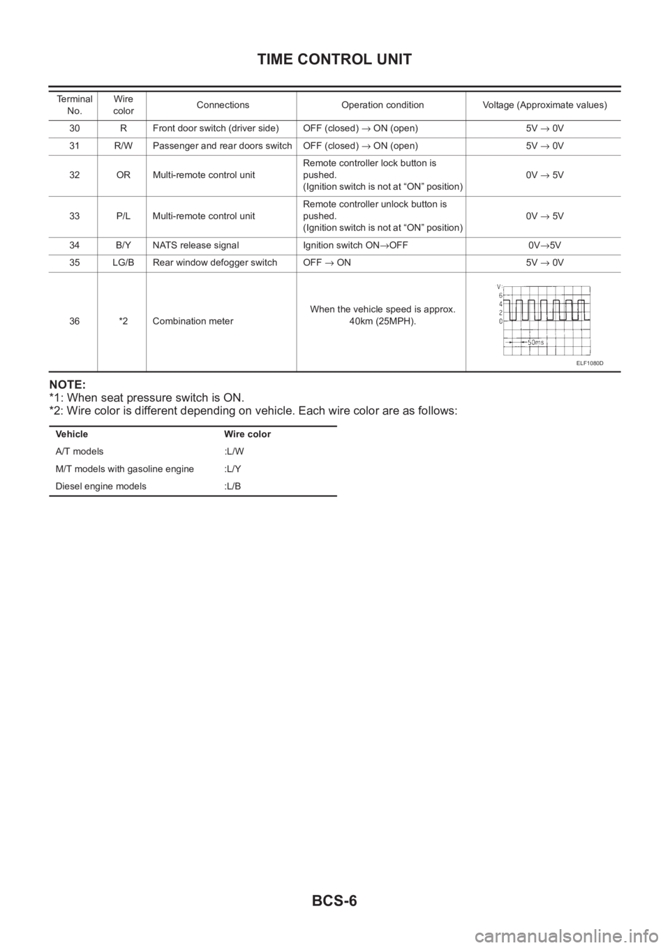
NOTE:
*1: When seat pressure switch is ON.
*2: Wire color is different depending on vehicle. Each wire color are as follows:
30 R Front door switch (driver side) OFF (closed) → ON (open) 5V → 0V
31 R/W Passenger and rear doors switch OFF (closed) → ON (open) 5V → 0V
32 OR Multi-remote control unitRemote controller lock button is
pushed.
(Ignition switch is not at “ON” position)0V → 5V
33 P/L Multi-remote control unitRemote controller unlock button is
pushed.
(Ignition switch is not at “ON” position)0V → 5V
34 B/Y NATS release signal Ignition switch ON→OFF 0V→5V
35 LG/B Rear window defogger switch OFF → ON 5V → 0V
36 *2 Combination meterWhen the vehicle speed is approx.
40km (25MPH). Te r m i n a l
No.Wire
colorConnections Operation condition Voltage (Approximate values)
ELF1080D
Vehicle Wire color
A/T models :L/W
M/T models with gasoline engine :L/Y
Diesel engine models :L/B
Page 3827 of 3833
IDX-3
A
C
D
E
F
G
H
I
J
K
L B
IDX
ALPHABETICAL INDEX
MTC-17,MTC-21
Blower resistor ................................................ MTC-22
Blower unit ...................................... ATC-116,MTC-21
Boring/horning cylinder block(QR20DE•QR25DE) .......
EM-93
Brake booster .................................................... BR-17
Brake fluid change ............................................... BR-9
Brake fluid level ................................................. MA-39
Brake fluid level and line check ........................... BR-9
Brake hydraulic line ........................................... BR-11
Brake inspection ................................................ MA-39
Brake lines and cables inspection ..................... MA-39
Brake master cylinder ........................................ BR-13
Brake pedal ......................................................... BR-6
Brake switch .... EC-349,EC-625,EC-1068,EC-1301,
EC-1558
BRK/SW - Wiring diagram EC-351,EC-627,EC-1070,
EC-1303
,EC-1559
Bulb specifications .............................................. LT-67
Bumper, front ......................................................... EI-6
Bumper, rear .......................................................... EI-9
C
Camshaft inspection(QR20DE•QR25DE) .......... EM-51
Camshaft inspection(YD22DDTi) .................... EM-159
Camshaft position sensor (CMPS) ................ EC-1484
Camshaft position sensor (PHASE) . EC-233,EC-557,
EC-962
,EC-1246
Camshaft(QR20DE•QR25DE) ........................... EM-46
Camshaft(YD22DDTi) ...................................... EM-158
CAN - Wiring diagram ......... EC-123,EC-514,EC-855,
EC-1200
,EC-1449,LAN-6,LAN-13
CAN (Controller Area Network) LAN-3,LAN-5,LAN-12
CAN Communication .......................................... TF-53
CAN communication ........... EC-122,EC-513,EC-854,
EC-1199
,EC-1448,AT-109,AT-190,AT-309,AT-403,
BRC-54
,BRC-62,BRC-92,BRC-110,LAN-3,LAN-5,
LAN-12
Canister-See EVAP canister ............ EC-427,EC-748,
EC-1114
,EC-1388
CHARGE - Wiring diagram ................................ SC-13
Charging system ................................................ SC-12
Chassis and body maintenance ........................ MA-35
CHIME - Wiring diagram ..................................... DI-59
CIGAR - Wiring diagram .................................. WW-25
Cigarette lighter ............................................... WW-25
Circuit breaker ................................................... PG-12
CKPS - Wiring diagram ................................. EC-1481
Clearance lamp ........................................ LT-4,LT-40
Clock ................................................................... DI-70
CLOCK - Wiring diagram .................................... DI-70
Closed loop control EC-34,EC-444,EC-766,EC-1130
Clutch cover ....................................................... CL-15
Clutch disc ......................................................... CL-15
Clutch master cylinder ......................................... CL-9
Clutch operating cylinder ................................... CL-11
Clutch pedal ......................................................... CL-5
Clutch release bearing ....................................... CL-13
Clutch release mechanism ................................ CL-13
Clutch withdrawal lever ...................................... CL-13
CMPS - Wiring diagram ................................. EC-1486
Coil spring (rear) ............................................... RSU-8
Collision diagnosis .......................................... SRS-47
Combination meter .................................... DI-4,DI-24
Combination switch ................................. LT-24,LT-44
Common rail fuel pressure sensor ................. EC-1468
Component Location (auto A/C) ......... ATC-34,MTC-4
Compression pressure(QR20DE•QR25DE) ..... EM-59
Compression pressure(YD22DDTi) ................ EM-182
Compressor clutch removal and installation .. ATC-135
Compressor special service tool ...................... ATC-14
Condenser ..................................................... ATC-143
Connecting rod bearing clearance(QR20DE•QR25DE)
EM-91
Connecting rod bearing clearance(YD22DDTi) EM-216
Connecting rod bushing clearance(QR20DE•QR25DE)
EM-91
Connecting rod bushing clearance(YD22DDTi) EM-210
Connecting rod(QR20DE•QR25DE) ................. EM-91
Connecting rod(YD22DDTi) .............. EM-207,EM-212
Console box - See Instrument panel .......... IP-3,IP-10
CONSULT for engine ........... EC-94,EC-486,EC-826,
EC-1173
,EC-1431
CONSULT for VDC ......................................... BRC-80
Control lever (M/T) ............................................. MT-13
Control unit ..................................... ATC-111,MTC-20
Control units (terminal arrangement) ................. PG-71
Controller Area Network (CAN) LAN-3,LAN-5,LAN-12
Converter housing installation ........... AT-419,AT-514
COOL/F - Wiring diagram EC-327,EC-607,EC-1054,
EC-1291
,EC-1510
Coolant replacement(QR20DE•QR25DE) ........ MA-19
Coolant replacement(YD22DDTi) ..................... MA-27
Cooling circuit (engine)(QR20DE•QR25DE) ....... CO-7
Cooling circuit (engine)(YD22DDTi) ................. CO-27
Cooling fan control system(QR20DE•QR25DE) CO-12
Cooling fan motor EC-336,EC-616,EC-1063,EC-1300
Cooling fan relay EC-336,EC-616,EC-1063,EC-1300
Cooling fan(QR20DE•QR25DE) ....................... CO-12
Cooling fan(YD22DDTi) .................................... CO-33
Coupling sleeve (M/T) ........................... MT-18,MT-23
Cowl top .............................................................. EI-12
Cowl top cover .................................................... EI-12
Crankcase ventilation system ........................ EC-1402
Crankcase ventilation system - See Positive crankcase
ventilation .......... EC-428
,EC-749,EC-1115,EC-1389
Crankshaft position sensor (POS) .... EC-227,EC-551,
EC-956
,EC-1240
Crankshaft position sensor (TDC) ................. EC-1479
Crankshaft(QR20DE•QR25DE) ........................ EM-74
CRFPS - Wiring diagram ............................... EC-1469
Cylinder block boring(QR20DE•QR25DE) ........ EM-94
Cylinder block boring(YD22DDTi) ................... EM-214
Cylinder block(QR20DE•QR25DE) ................... EM-73
Cylinder block(YD22DDTi) .............................. EM-197
Cylinder head bolt tightening(QR20DE•QR25DE) ........
EM-61