2001 NISSAN X-TRAIL Combination
[x] Cancel search: CombinationPage 2086 of 3833

AT-8
PRECAUTIONS
●Converter is contaminated with engine coolant containing antifreeze.
●Internal failure of stator roller clutch.
●Heavy clutch debris due to overheating (blue converter).
●Steel particles or clutch lining material found in fluid filter or on magnet when no internal parts in unit are
worn or damaged — indicates that lining material came from converter.
The torque converter should not be replaced if:
●The fluid has an odor, is discolored, and there is no evidence of metal or clutch facing particles.
●The threads in one or more of the converter bolt holes are damaged.
●Transaxle failure did not display evidence of damaged or worn internal parts, steel particles or clutch plate
lining material in unit and inside the fluid filter.
●Vehicle has been exposed to high mileage (only). The exception may be where the torque converter
clutch dampener plate lining has seen excess wear by vehicles operated in heavy and/or constant traffic,
such as taxi, delivery or police use.
EURO-OBD SELF-DIAGNOSIS — EURO-OBD —
●A/T self-diagnosis is performed by the TCM in combination with the ECM. The results can be read through
the blinking pattern of the O/D OFF indicator lamp or the malfunction indicator lamp (MIL). Refer to the
table on AT- 4 2 , "
SELF-DIAGNOSTIC RESULT TEST MODE" for the indicator used to display each self-
diagnostic result.
●The self-diagnostic results indicated by the MIL are automatically stored in both the ECM and TCM mem-
ories.
Always perform the procedure “HOW TO ERASE DTC” on AT- 3 9 , "
HOW TO ERASE DTC" to com-
plete the repair and avoid unnecessary blinking of the MIL.
●The following self-diagnostic items can be detected using ECM self-diagnostic results mode* only when
the O/D OFF indicator lamp does not indicate any malfunctions.
–PNP switch
–A/T 1st, 2nd, 3rd, or 4th gear function
*: For details of EURO-OBD, refer to EC-44, "
ON BOARD DIAGNOSTIC (OBD) SYSTEM" (QR25DE) or EC-
777, "ON BOARD DIAGNOSTIC (OBD) SYSTEM" (QR20DE).
●Certain systems and components, especially those related to EURO-OBD, may use a new style
slide-locking type harness connector.
For description and how to disconnect, refer to PG-68, "
HARNESS CONNECTOR" .
Wiring Diagrams and Trouble DiagnosisECS004Q4
When you read wiring diagrams, refer to the following:
●GI-13, "How to Read Wiring Diagrams"
●PG-2, "POWER SUPPLY ROUTING"
When you perform trouble diagnosis, refer to the following:
●GI-10, "HOW TO FOLLOW TEST GROUPS IN TROUBLE DIAGNOSES"
●GI-23, "How to Perform Efficient Diagnosis for an Electrical Incident"
Page 2110 of 3833

AT-32
OVERALL SYSTEM
Torque Converter Clutch Solenoid Valve Control
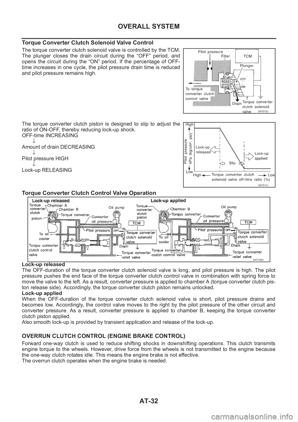
The torque converter clutch solenoid valve is controlled by the TCM.
The plunger closes the drain circuit during the “OFF” period, and
opens the circuit during the “ON” period. If the percentage of OFF-
time increases in one cycle, the pilot pressure drain time is reduced
and pilot pressure remains high.
The torque converter clutch piston is designed to slip to adjust the
ratio of ON-OFF, thereby reducing lock-up shock.
OFF-time INCREASING
↓
Amount of drain DECREASING
↓
Pilot pressure HIGH
↓
Lock-up RELEASING
Torque Converter Clutch Control Valve Operation
Lock-up released
The OFF-duration of the torque converter clutch solenoid valve is long, and pilot pressure is high. The pilot
pressure pushes the end face of the torque converter clutch control valve in combination with spring force to
move the valve to the left. As a result, converter pressure is applied to chamber A (torque converter clutch pis-
ton release side). Accordingly, the torque converter clutch piston remains unlocked.
Lock-up applied
When the OFF-duration of the torque converter clutch solenoid valve is short, pilot pressure drains and
becomes low. Accordingly, the control valve moves to the right by the pilot pressure of the other circuit and
converter pressure. As a result, converter pressure is applied to chamber B, keeping the torque converter
clutch piston applied.
Also smooth lock-up is provided by transient application and release of the lock-up.
OVERRUN CLUTCH CONTROL (ENGINE BRAKE CONTROL)
Forward one-way clutch is used to reduce shifting shocks in downshifting operations. This clutch transmits
engine torque to the wheels. However, drive force from the wheels is not transmitted to the engine because
the one-way clutch rotates idle. This means the engine brake is not effective.
The overrun clutch operates when the engine brake is needed.
SAT010J
SAT011J
AAT155A
Page 2112 of 3833

AT-34
OVERALL SYSTEM
Control Valve
ECS004QG
FUNCTION OF CONTROL VALVES
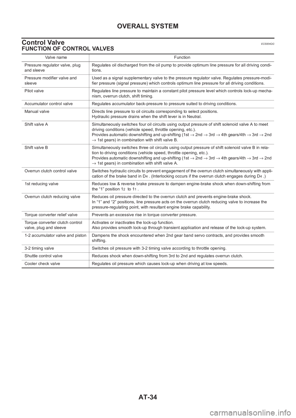
Valve name Function
Pressure regulator valve, plug
and sleeveRegulates oil discharged from the oil pump to provide optimum line pressure for all driving condi-
tions.
Pressure modifier valve and
sleeveUsed as a signal supplementary valve to the pressure regulator valve. Regulates pressure-modi-
fier pressure (signal pressure) which controls optimum line pressure for all driving conditions.
Pilot valve Regulates line pressure to maintain a constant pilot pressure level which controls lock-up mecha-
nism, overrun clutch, shift timing.
Accumulator control valve Regulates accumulator back-pressure to pressure suited to driving conditions.
Manual valve Directs line pressure to oil circuits corresponding to select positions.
Hydraulic pressure drains when the shift lever is in Neutral.
Shift valve A Simultaneously switches four oil circuits using output pressure of shift solenoid valve A to meet
driving conditions (vehicle speed, throttle opening, etc.).
Provides automatic downshifting and up-shifting (1st → 2nd → 3rd → 4th gears/4th → 3rd → 2nd
→ 1st gears) in combination with shift valve B.
Shift valve B Simultaneously switches three oil circuits using output pressure of shift solenoid valve B in rela-
tion to driving conditions (vehicle speed, throttle opening, etc.).
Provides automatic downshifting and up-shifting (1st → 2nd → 3rd → 4th gears/4th → 3rd → 2nd
→ 1st gears) in combination with shift valve A.
Overrun clutch control valve Switches hydraulic circuits to prevent engagement of the overrun clutch simultaneously with appli-
cation of the brake band in D
4 . (Interlocking occurs if the overrun clutch engages during D4 .)
1st reducing valve Reduces low & reverse brake pressure to dampen engine-brake shock when down-shifting from
the “1” position 1
2 to 11 .
Overrun clutch reducing valve Reduces oil pressure directed to the overrun clutch and prevents engine-brake shock.
In “1” and “2” positions, line pressure acts on the overrun clutch reducing valve to increase the
pressure-regulating point, with resultant engine brake capability.
Torque converter relief valve Prevents an excessive rise in torque converter pressure.
Torque converter clutch control
valve, plug and sleeveActivates or inactivates the lock-up function.
Also provides smooth lock-up through transient application and release of the lock-up system.
1-2 accumulator valve and piston Dampens the shock encountered when 2nd gear band servo contracts, and provides smooth
shifting.
3-2 timing valve Switches oil pressure with 3-2 timing valve according to throttle opening.
Shuttle control valve Reduces shock when down-shifting from 3rd to 2nd and regulates overrun clutch.
Cooler check valve Regulates oil pressure which causes lock-up when driving at low speeds.
Page 2277 of 3833
![NISSAN X-TRAIL 2001 Service Repair Manual DTC VEHICLE SPEED SENSOR MTR
AT-199
[EURO-OBD]
D
E
F
G
H
I
J
K
L
MA
B
AT
DTC VEHICLE SPEED SENSOR MTRPFP:24814
DescriptionECS004SM
The vehicle speed sensor·MTR is built into the speedometer assem-
bl NISSAN X-TRAIL 2001 Service Repair Manual DTC VEHICLE SPEED SENSOR MTR
AT-199
[EURO-OBD]
D
E
F
G
H
I
J
K
L
MA
B
AT
DTC VEHICLE SPEED SENSOR MTRPFP:24814
DescriptionECS004SM
The vehicle speed sensor·MTR is built into the speedometer assem-
bl](/manual-img/5/57405/w960_57405-2276.png)
DTC VEHICLE SPEED SENSOR MTR
AT-199
[EURO-OBD]
D
E
F
G
H
I
J
K
L
MA
B
AT
DTC VEHICLE SPEED SENSOR MTRPFP:24814
DescriptionECS004SM
The vehicle speed sensor·MTR is built into the speedometer assem-
bly. The sensor functions as an auxiliary device to the revolution sen-
sor when it is malfunctioning. The TCM will then use a signal sent
from the vehicle speed sensor·MTR.
TCM TERMINALS AND REFERENCE VALUE
Remarks: Specification data are reference values.
ON BOARD DIAGNOSIS LOGIC
SCIA0716E
Te r m i -
nal No.Wire color Item ConditionJudgement stan-
dard
(Approx.)
40 L/BVehicle speed
sensorWhen moving vehicle at 2 to 3 km/h
(1 to 2 MPH) for 1 m (3 ft) or more.Voltage varies
between less
than 1V and
more than 4.5V
Diagnostic trouble code Malfunction is detected when... Check items (Possible cause)
: VHCL SPEED SEN·MTR
TCM does not receive the proper voltage
signal from the sensor.
●Harness or connectors
(The sensor circuit is open or shorted.)
●Combination meter
●4WD/ABS control unit : 2nd judgement flicker
Page 2280 of 3833
![NISSAN X-TRAIL 2001 Service Repair Manual AT-202
[EURO-OBD]
DTC VEHICLE SPEED SENSOR MTR
Diagnostic Procedure
ECS004SO
1. CHECK INPUT SIGNAL
With CONSULT-II
1. Start engine.
2. Select “TCM INPUT SIGNALS” in “DATA MONITOR” mode NISSAN X-TRAIL 2001 Service Repair Manual AT-202
[EURO-OBD]
DTC VEHICLE SPEED SENSOR MTR
Diagnostic Procedure
ECS004SO
1. CHECK INPUT SIGNAL
With CONSULT-II
1. Start engine.
2. Select “TCM INPUT SIGNALS” in “DATA MONITOR” mode](/manual-img/5/57405/w960_57405-2279.png)
AT-202
[EURO-OBD]
DTC VEHICLE SPEED SENSOR MTR
Diagnostic Procedure
ECS004SO
1. CHECK INPUT SIGNAL
With CONSULT-II
1. Start engine.
2. Select “TCM INPUT SIGNALS” in “DATA MONITOR” mode for
“A/T” with CONSULT-II.
3. Read out the value of “VHCL/S SE·MTR” while driving.
Check the value changes according to driving speed.
Without CONSULT-II
1. Start engine.
2. Check voltage between TCM terminal 40 and ground while driv-
ing at 2 to 3 km/h (1 to 2 MPH) for 1 m (3 ft) or more.
OK or NG
OK >> GO TO 2.
NG >> Check the following items. If any items are damaged,
repair or replace damaged parts.
●Combination meter
Refer to DI-4, "
COMBINATION METERS (LHD MODELS)" or DI-24, "COMBINATION
METERS (RHD MODELS)" .
●Harness for short or open between TCM and combination meter
●4WD/ABS control unit
Refer to BRC-24, "
SELF-DIAGNOSIS" .
●Harness for short or open between 4WD/ABS control unit and combination meter
2. CHECK DTC
Perform Diagnostic Trouble Code (DTC) confirmation procedure. Refer to AT- 2 0 0 , "
DIAGNOSTIC TROUBLE
CODE (DTC) CONFIRMATION PROCEDURE" .
OK or NG
OK >>INSPECTION END
NG >> 1. Perform TCM input/output signal inspection.
2. If NG, recheck TCM pin terminals for damage or loose connection with harness connector.
SAT614J
Voltage: Voltage varies between less than 1V and
more than 4.5V.
SCIA0717E
Page 2436 of 3833
![NISSAN X-TRAIL 2001 Service Repair Manual AT-358
[ALL]
DTC VEHICLE SPEED SENSOR MTR
DTC VEHICLE SPEED SENSOR MTR
PFP:24814
DescriptionECS004TM
The vehicle speed sensor·MTR is built into the speedometer assem-
bly. The sensor functions as an NISSAN X-TRAIL 2001 Service Repair Manual AT-358
[ALL]
DTC VEHICLE SPEED SENSOR MTR
DTC VEHICLE SPEED SENSOR MTR
PFP:24814
DescriptionECS004TM
The vehicle speed sensor·MTR is built into the speedometer assem-
bly. The sensor functions as an](/manual-img/5/57405/w960_57405-2435.png)
AT-358
[ALL]
DTC VEHICLE SPEED SENSOR MTR
DTC VEHICLE SPEED SENSOR MTR
PFP:24814
DescriptionECS004TM
The vehicle speed sensor·MTR is built into the speedometer assem-
bly. The sensor functions as an auxiliary device to the revolution sen-
sor when it is malfunctioning. The TCM will then use a signal sent
from the vehicle speed sensor·MTR.
TCM TERMINALS AND REFERENCE VALUE
Remarks: Specification data are reference values.
ON BOARD DIAGNOSIS LOGIC
SELF-DIAGNOSIS CODE CONFIRMATION PROCEDURE
After the repair, perform the following procedure to confirm the malfunction is eliminated.
With CONSULT-II
1. Start engine.
2. Select “SELF-DIAG RESULTS” mode for A/T with CONSULT-II.
3. Drive vehicle under the following conditions:
Selector lever in “D” position and vehicle speed higher than 20
km/h (12 MPH).
SCIA0716E
Te r m i -
nal No.Wire color Item ConditionJudgement stan-
dard
(Approx.)
40 L/BVehicle speed
sensorWhen moving vehicle at 2 to 3 km/h
(1 to 2 MPH) for 1 m (3 ft) or more.Voltage varies
between less
than 0V and
more than 4.5V
Diagnostic trouble code Malfunction is detected when... Check items (Possible cause)
: VHCL SPEED SEN·MTR
TCM does not receive the proper voltage
signal from the sensor.
●Harness or connectors
(The sensor circuit is open or shorted.)
●Combination meter
●4WD/ABS control unit : 2nd judgement flicker
SAT014K
Page 2439 of 3833
![NISSAN X-TRAIL 2001 Service Repair Manual DTC VEHICLE SPEED SENSOR MTR
AT-361
[ALL]
D
E
F
G
H
I
J
K
L
MA
B
AT
Diagnostic ProcedureECS004TO
1.CHECK INPUT SIGNAL
With CONSULT-II
1. Start engine.
2. Select “TCM INPUT SIGNALS” in “DATA MONI NISSAN X-TRAIL 2001 Service Repair Manual DTC VEHICLE SPEED SENSOR MTR
AT-361
[ALL]
D
E
F
G
H
I
J
K
L
MA
B
AT
Diagnostic ProcedureECS004TO
1.CHECK INPUT SIGNAL
With CONSULT-II
1. Start engine.
2. Select “TCM INPUT SIGNALS” in “DATA MONI](/manual-img/5/57405/w960_57405-2438.png)
DTC VEHICLE SPEED SENSOR MTR
AT-361
[ALL]
D
E
F
G
H
I
J
K
L
MA
B
AT
Diagnostic ProcedureECS004TO
1.CHECK INPUT SIGNAL
With CONSULT-II
1. Start engine.
2. Select “TCM INPUT SIGNALS” in “DATA MONITOR” mode for “A/T” with CONSULT-II.
3. Read out the value of “VHCL/S SE·MTR” while driving.
Check the value changes according to driving speed.
Without CONSULT-II
1. Start engine.
2. Check voltage between TCM terminal 40 and ground while driv-
ing at 2 to 3 km/h (1 to 2 MPH) for 1 m (3 ft) or more.
OK or NG
OK >> GO TO 2
NG >> Check the following items. If any items are damaged, repair or replace damaged parts.
●Combination meter
Refer to DI-4, "
COMBINATION METERS (LHD MODELS)" or DI-24, "COMBINATION
METERS (RHD MODELS)" .
●Harness for short or open between TCM and combination meter
●4WD/ABS control unit
Refer to BRC-24, "
SELF-DIAGNOSIS" .
●Harness for short or open between 4WD/ABS control unit and combination meter
2.CHECK DTC
Perform Self-diagnosis Code confirmation procedure, AT- 3 5 8 , "
SELF-DIAGNOSIS CODE CONFIRMATION
PROCEDURE" .
OK or NG
OK >>INSPECTION END
NG >> 1. Perform TCM input/output signal inspection.
2. If NG, recheck TCM pin terminals for damage or loose connection with harness connector. Voltage: Voltage varies between less than 1V and
more than 4.5V.
SAT614J
SCIA0717E
Page 2665 of 3833

TROUBLE DIAGNOSIS
TF-55
C
E
F
G
H
I
J
K
L
MA
B
TF
Trouble Diagnoses for SymptomsEDS000IS
4WD INDICATOR LAMP DOSE NOT COME ON FOR APPROXIMATELY 1 SECOND WHEN THE
IGNITION SWITCH IS TURNED TO ON
Inspection Procedure
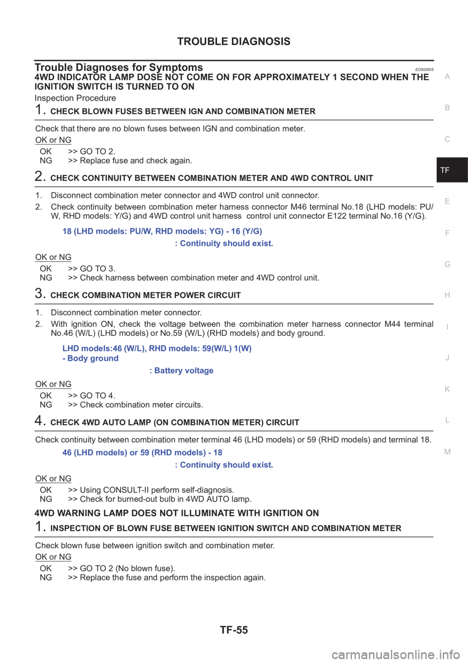
1.CHECK BLOWN FUSES BETWEEN IGN AND COMBINATION METER
Check that there are no blown fuses between IGN and combination meter.
OK or NG
OK >> GO TO 2.
NG >> Replace fuse and check again.
2.CHECK CONTINUITY BETWEEN COMBINATION METER AND 4WD CONTROL UNIT
1. Disconnect combination meter connector and 4WD control unit connector.
2. Check continuity between combination meter harness connector M46 terminal No.18 (LHD models: PU/
W, RHD models: Y/G) and 4WD control unit harness control unit connector E122 terminal No.16 (Y/G).
OK or NG
OK >> GO TO 3.
NG >> Check harness between combination meter and 4WD control unit.
3.CHECK COMBINATION METER POWER CIRCUIT
1. Disconnect combination meter connector.
2. With ignition ON, check the voltage between the combination meter harness connector M44 terminal
No.46 (W/L) (LHD models) or No.59 (W/L) (RHD models) and body ground.
OK or NG
OK >> GO TO 4.
NG >> Check combination meter circuits.
4.CHECK 4WD AUTO LAMP (ON COMBINATION METER) CIRCUIT
Check continuity between combination meter terminal 46 (LHD models) or 59 (RHD models) and terminal 18.
OK or NG
OK >> Using CONSULT-II perform self-diagnosis.
NG >> Check for burned-out bulb in 4WD AUTO lamp.
4WD WARNING LAMP DOES NOT ILLUMINATE WITH IGNITION ON
1.INSPECTION OF BLOWN FUSE BETWEEN IGNITION SWITCH AND COMBINATION METER
Check blown fuse between ignition switch and combination meter.
OK or NG
OK >> GO TO 2 (No blown fuse).
NG >> Replace the fuse and perform the inspection again.18 (LHD models: PU/W, RHD models: YG) - 16 (Y/G)
: Continuity should exist.
LHD models:46 (W/L), RHD models: 59(W/L) 1(W)
- Body ground
: Battery voltage
46 (LHD models) or 59 (RHD models) - 18
: Continuity should exist.