Page 3032 of 3833
SRS-30
DRIVER AIR BAG MODULE
CAUTION:
●Always work from the side of driver air bag module.
●Always place driver air bag module with pad side facing
upward.
●Do not insert any foreign objects (screwdriver, etc.) into
driver air bag module.
●Do not attempt to disassemble driver air bag module.
●Do not use old bolts after removal; replace with new bolts.
●Do not expose the driver air bag module to temperatures
exceeding 90°C(194°F).
●Replace air bag module if it has been dropped or sustained
an impact.
●Do not allow oil, grease or water to come in contact with the
front passenger air bag module.
INSTALLATION
To install, reverse the removal procedure sequence.
●After installing the air bag module, check that the contact clear-
ance of the horn switch is in the specified range in the right.
●For installing the air bag module, tighten the special bolts with
the center of the horn pad pressed to make the contacts (RH/
LH) ON.
SRS443
SBF814E
SHIA0185E
SHIA0184E
Page 3034 of 3833
SRS-32
DRIVER AIR BAG MODULE
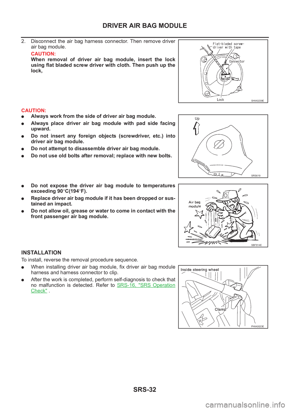
2. Disconnect the air bag harness connector. Then remove driver
air bag module.
CAUTION:
When removal of driver air bag module, insert the lock
using flat bladed screw driver with cloth. Then push up the
lock,
CAUTION:
●Always work from the side of driver air bag module.
●Always place driver air bag module with pad side facing
upward.
●Do not insert any foreign objects (screwdriver, etc.) into
driver air bag module.
●Do not attempt to disassemble driver air bag module.
●Do not use old bolts after removal; replace with new bolts.
●Do not expose the driver air bag module to temperatures
exceeding 90°C(194°F).
●Replace driver air bag module if it has been dropped or sus-
tained an impact.
●Do not allow oil, grease or water to come in contact with the
front passenger air bag module.
INSTALLATION
To install, reverse the removal procedure sequence.
●When installing driver air bag module, fix driver air bag module
harness and harness connector to clip.
●After the work is completed, perform self-diagnosis to check that
no malfunction is detected. Refer to SRS-16, "
SRS Operation
Check" .
SHIA0239E
SRS619
SBF814E
PHIA0023E
Page 3037 of 3833
FRONT PASSENGER AIR BAG MODULE
SRS-35
C
D
E
F
G
I
J
K
L
MA
B
SRS
FRONT PASSENGER AIR BAG MODULEPFP:K8515
Removal and InstallationEHS000D9
REMOVAL
CAUTION:
●Before servicing SRS, turn the ignition switch off, disconnect both battery cables and wait at least
3 minutes.
●Always work from the side of or under front passenger air bag module.
1. Remove the glove box. Refer to IP-3, "
INSTRUMENT PANEL ASSEMBLY" .
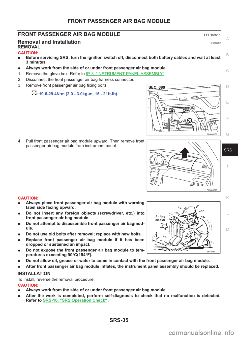
2. Disconnect the front passenger air bag harness connector.
3. Remove front passenger air bag fixing bolts
4. Pull front passenger air bag module upward. Then remove front
passenger air bag module from instrument panel.
CAUTION:
●Always place front passenger air bag module with warning
label side facing upward.
●Do not insert any foreign objects (screwdriver, etc.) into
front passenger air bag module.
●Do not attempt to disassemble front passenger air bagmod-
ule.
●Do not use old bolts after removal; replace with new bolts.
●Replace front passenger air bag module if it has been
dropped or sustained an impact.
●Do not expose the front passenger air bag module to tem-
peratures exceeding 90°C(194°F).
●Do not allow oil, grease or water to come in contact with the front passenger air bag module.
●After front passenger air bag module inflates, the instrument panel assembly should be replaced.
INSTALLATION
To install, reverse the removal procedure.
CAUTION:
●Always work from the side of or under front passenger air bag module.
●After the work is completed, perform self-diagnosis to check that no malfunction is detected.
Refer to SRS-16, "
SRS Operation Check" . : 19.6-29.4N·m (2.0 - 3.0kg-m, 15 - 21ft-lb)
PHIA0027E
PHIA0026E
SBF814E
Page 3172 of 3833
GW-20
REAR WINDOW DEFOGGER
Electrical Components Inspection
EIS0045U
REAR WINDOW DEFOGGER RELAY (WITH DOOR MIRROR DEFOGGER)
Check continuity between terminals 3 and 5, 6 and 7.
REAR WINDOW DEFOGGER RELAY (WITHOUT DOOR MIRROR DEFOGGER)
Check continuity between terminals 3 and 5.
REAR WINDOW DEFOGGER SWITCH
Check continuity between terminals when rear window defogger
switch is pushed and released.
FILAMENT CHECK
1. When measuring voltage, wrap tin foil around the top of the neg-
ative probe.Then press the foil against the wire with your finder.
Condition Continuity
12V direct current supply between ter-
minals 1 and 2Ye s
No current supply No
SEC202B
Condition Continuity
12V direct current supply between ter-
minals 1 and 2Ye s
No current supply No
PIIA2636E
Connector Condition Continuity
M50 1 – 2Rear window defogger
switch is pushed.Ye s
Rear window defogger
switch is released.No
SIIA1203E
SEL122R
Page 3286 of 3833
ATC-10
PRECAUTIONS
●After compressor service operation, turn the compressor shaft by hand more than five turns in
both directions. This will equally distribute lubricant inside the compressor. After the compressor
is installed, let the engine idle and operate the compressor for one hour.
●After replacing the compressor magnet clutch, apply voltage to the new one and check for normal
operation.
Precautions for Service EquipmentEJS000T6
RECOVERY/RECYCLING EQUIPMENT
Be certain to follow the manufacturers instructions for machine operation and machine maintenance. Never
introduce any refrigerant other than that specified into the machine.
ELECTRONIC LEAK DETECTOR
Be certain to follow the manufacturer's instructions for tester operation and tester maintenance.
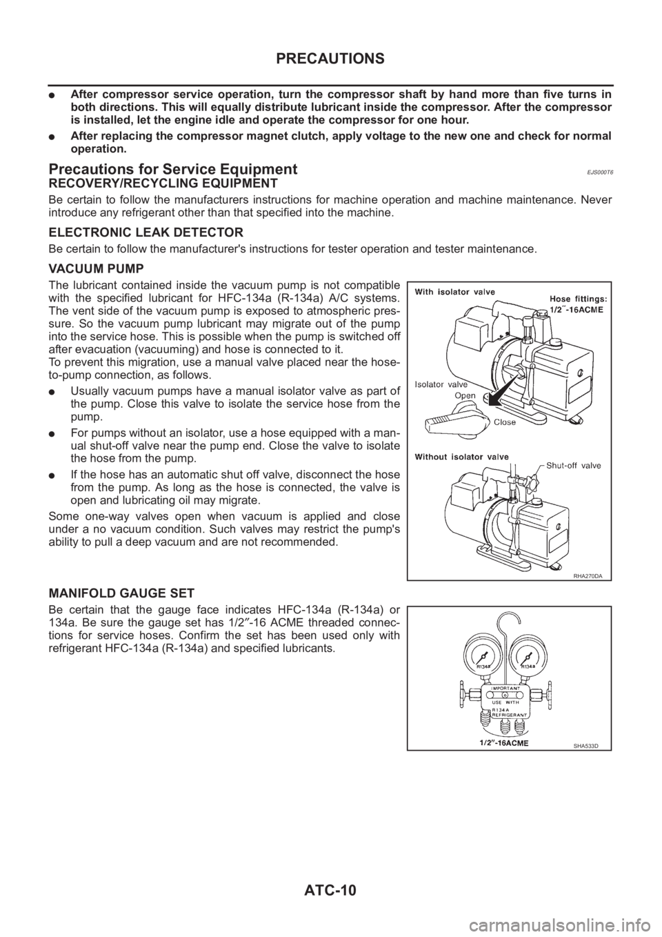
VACUUM PUMP
The lubricant contained inside the vacuum pump is not compatible
with the specified lubricant for HFC-134a (R-134a) A/C systems.
The vent side of the vacuum pump is exposed to atmospheric pres-
sure. So the vacuum pump lubricant may migrate out of the pump
into the service hose. This is possible when the pump is switched off
after evacuation (vacuuming) and hose is connected to it.
To prevent this migration, use a manual valve placed near the hose-
to-pump connection, as follows.
●Usually vacuum pumps have a manual isolator valve as part of
the pump. Close this valve to isolate the service hose from the
pump.
●For pumps without an isolator, use a hose equipped with a man-
ual shut-off valve near the pump end. Close the valve to isolate
the hose from the pump.
●If the hose has an automatic shut off valve, disconnect the hose
from the pump. As long as the hose is connected, the valve is
open and lubricating oil may migrate.
Some one-way valves open when vacuum is applied and close
under a no vacuum condition. Such valves may restrict the pump's
ability to pull a deep vacuum and are not recommended.
MANIFOLD GAUGE SET
Be certain that the gauge face indicates HFC-134a (R-134a) or
134a. Be sure the gauge set has 1/2″-16 ACME threaded connec-
tions for service hoses. Confirm the set has been used only with
refrigerant HFC-134a (R-134a) and specified lubricants.
RHA270DA
SHA533D
Page 3292 of 3833
ATC-16
PREPARATION
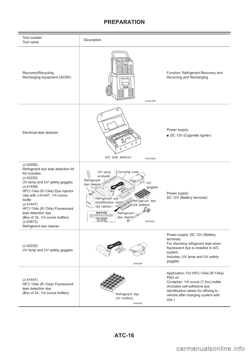
Recovery/Recycling
Recharging equipment (ACR4)Function: Refrigerant Recovery and
Recycling and Recharging
Electrical leak detectorPower supply:
●DC 12V (Cigarette lighter)
(J-43926)
Refrigerant dye leak detection kit
Kit includes:
(J-42220)
UV lamp and UV safety goggles
(J-41459)
HFC-134a (R-134a) Dye injector
Use with J-41447, 1/4 ounce
bottle
(J-41447)
HFC-134a (R-134a) Fluorescent
leak detection dye
(Box of 24, 1/4 ounce bottles)
(J-43872)
Refrigerant dye cleanerPower supply:
DC 12V (Battery terminal)
(J-42220)
UV lamp and UV safety gogglesPower supply: DC 12V (Battery
terminal)
For checking refrigerant leak when
fluorescent dye is installed in A/C
system.
Includes: UV lamp and UV safety
goggles
(J-41447)
HFC-134a (R-134a) Fluorescent
leak detection dye
(Box of 24, 1/4 ounce bottles)Application: For HFC-134a (R-134a)
PAG oil
Container: 1/4 ounce (7.4cc) bottle
(Includes self-adhesive dye
identification labels for affixing to
vehicle after charging system with
dye.) Tool number
Tool nameDescription
RJIA0195E
SHA705EB
ZHA200H
SHA438F
SHA439F
Page 3300 of 3833
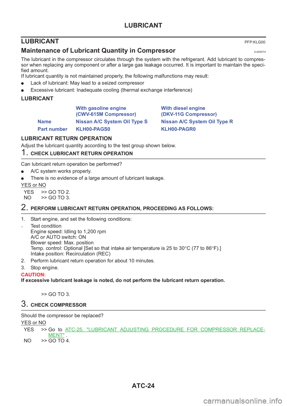
ATC-24
LUBRICANT
LUBRICANT
PFP:KLG00
Maintenance of Lubricant Quantity in CompressorEJS000TH
The lubricant in the compressor circulates through the system with the refrigerant. Add lubricant to compres-
sor when replacing any component or after a large gas leakage occurred. It is important to maintain the speci-
fied amount.
If lubricant quantity is not maintained properly, the following malfunctions may result:
●Lack of lubricant: May lead to a seized compressor
●Excessive lubricant: Inadequate cooling (thermal exchange interference)
LUBRICANT
LUBRICANT RETURN OPERATION
Adjust the lubricant quantity according to the test group shown below.
1. CHECK LUBRICANT RETURN OPERATION
Can lubricant return operation be performed?
●A/C system works properly.
●There is no evidence of a large amount of lubricant leakage.
YES or NO
YES >> GO TO 2.
NO >> GO TO 3.
2. PERFORM LUBRICANT RETURN OPERATION, PROCEEDING AS FOLLOWS:
1. Start engine, and set the following conditions:
–Test condition
Engine speed: Idling to 1,200 rpm
A/C or AUTO switch: ON
Blower speed: Max. position
Temp. control: Optional [Set so that intake air temperature is 25 to 30°C (77 to 86°F).]
Intake position: Recirculation (REC)
2. Perform lubricant return operation for about 10 minutes.
3. Stop engine.
CAUTION:
If excessive lubricant leakage is noted, do not perform the lubricant return operation.
>> GO TO 3.
3. CHECK COMPRESSOR
Should the compressor be replaced?
YES or NO
YES >> Go to AT C - 2 5 , "LUBRICANT ADJUSTING PROCEDURE FOR COMPRESSOR REPLACE-
MENT" .
NO >> GO TO 4.With gasoline engine
(CWV-615M Compressor)With diesel engine
(DKV-11G Compressor)
Name Nissan A/C System Oil Type S Nissan A/C System Oil Type R
Part number KLH00-PAGS0 KLH00-PAGR0
Page 3356 of 3833
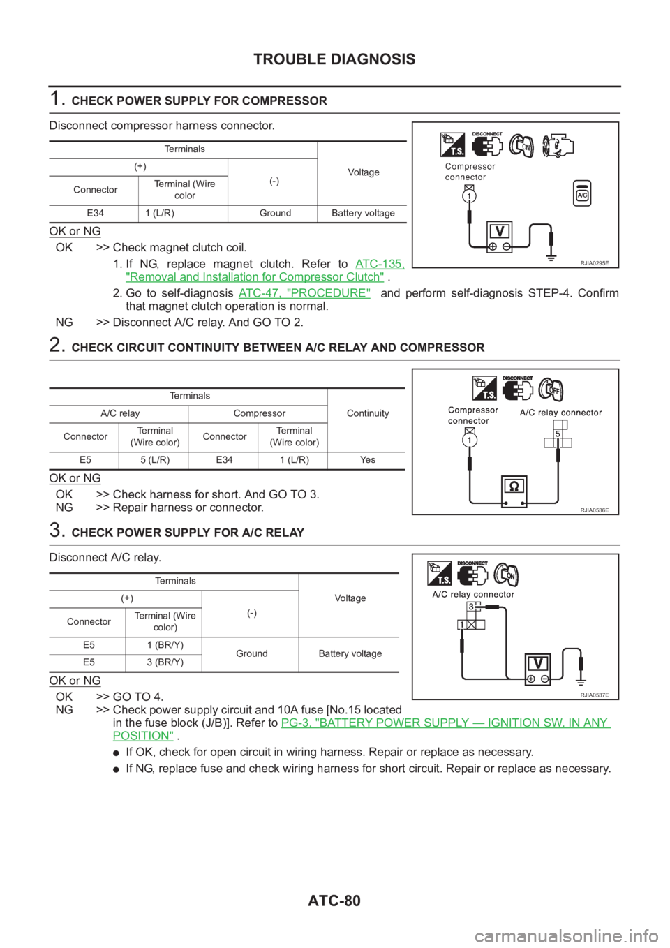
ATC-80
TROUBLE DIAGNOSIS
1. CHECK POWER SUPPLY FOR COMPRESSOR
Disconnect compressor harness connector.
OK or NG
OK >> Check magnet clutch coil.
1. If NG, replace magnet clutch. Refer to ATC-135,
"Removal and Installation for Compressor Clutch" .
2. Go to self-diagnosis AT C - 4 7 , "
PROCEDURE" and perform self-diagnosis STEP-4. Confirm
that magnet clutch operation is normal.
NG >> Disconnect A/C relay. And GO TO 2.
2. CHECK CIRCUIT CONTINUITY BETWEEN A/C RELAY AND COMPRESSOR
OK or NG
OK >> Check harness for short. And GO TO 3.
NG >> Repair harness or connector.
3. CHECK POWER SUPPLY FOR A/C RELAY
Disconnect A/C relay.
OK or NG
OK >> GO TO 4.
NG >> Check power supply circuit and 10A fuse [No.15 located
in the fuse block (J/B)]. Refer to PG-3, "
BATTERY POWER SUPPLY — IGNITION SW. IN ANY
POSITION" .
●If OK, check for open circuit in wiring harness. Repair or replace as necessary.
●If NG, replace fuse and check wiring harness for short circuit. Repair or replace as necessary.
Te r m i n a l s
Voltag e (+)
(-)
ConnectorTe r m i n a l ( W i r e
color
E34 1 (L/R) Ground Battery voltage
RJIA0295E
Terminals
Continuity A/C relay Compressor
ConnectorTerminal
(Wire color)ConnectorTerminal
(Wire color)
E5 5 (L/R) E34 1 (L/R) Yes
RJIA0536E
Te r m i n a l s
Voltage (+)
(-)
ConnectorTe r m i n a l ( W i r e
color)
E5 1 (BR/Y)
Ground Battery voltage
E5 3 (BR/Y)
RJIA0537E