2001 NISSAN X-TRAIL check oil
[x] Cancel search: check oilPage 2701 of 3833
REAR FINAL DRIVE ASSEMBLY
RFD-25
C
E
F
G
H
I
J
K
L
MA
B
RFD
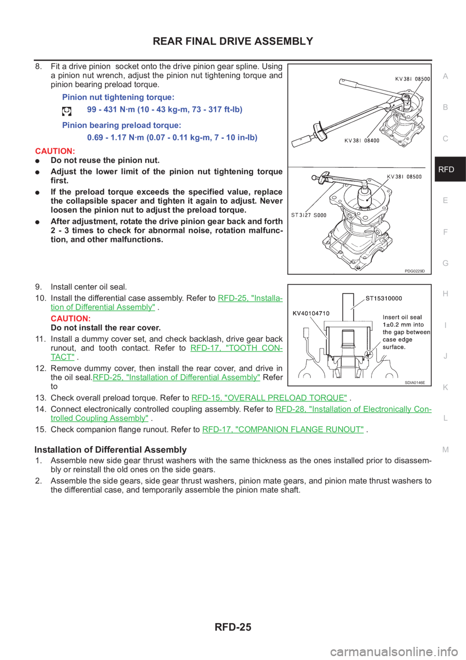
8. Fit a drive pinion socket onto the drive pinion gear spline. Using
a pinion nut wrench, adjust the pinion nut tightening torque and
pinion bearing preload torque.
CAUTION:
●Do not reuse the pinion nut.
●Adjust the lower limit of the pinion nut tightening torque
first.
●If the preload torque exceeds the specified value, replace
the collapsible spacer and tighten it again to adjust. Never
loosen the pinion nut to adjust the preload torque.
●After adjustment, rotate the drive pinion gear back and forth
2 - 3 times to check for abnormal noise, rotation malfunc-
tion, and other malfunctions.
9. Install center oil seal.
10. Install the differential case assembly. Refer to RFD-25, "
Installa-
tion of Differential Assembly" .
CAUTION:
Do not install the rear cover.
11. Install a dummy cover set, and check backlash, drive gear back
runout, and tooth contact. Refer to RFD-17, "
TOOTH CON-
TA C T" .
12. Remove dummy cover, then install the rear cover, and drive in
the oil seal.RFD-25, "
Installation of Differential Assembly" Refer
to
13. Check overall preload torque. Refer to RFD-15, "
OVERALL PRELOAD TORQUE" .
14. Connect electronically controlled coupling assembly. Refer to RFD-28, "
Installation of Electronically Con-
trolled Coupling Assembly" .
15. Check companion flange runout. Refer to RFD-17, "
COMPANION FLANGE RUNOUT" .
Installation of Differential Assembly
1. Assemble new side gear thrust washers with the same thickness as the ones installed prior to disassem-
bly or reinstall the old ones on the side gears.
2. Assemble the side gears, side gear thrust washers, pinion mate gears, and pinion mate thrust washers to
the differential case, and temporarily assemble the pinion mate shaft. Pinion nut tightening torque:
99 - 431 N·m (10 - 43 kg-m, 73 - 317 ft-lb)
Pinion bearing preload torque:
0.69 - 1.17 N·m (0.07 - 0.11 kg-m, 7 - 10 in-lb)
PDG0229D
SDIA0146E
Page 2703 of 3833
REAR FINAL DRIVE ASSEMBLY
RFD-27
C
E
F
G
H
I
J
K
L
MA
B
RFD
9. Apply differential oil to the side bearings, and assemble new side bearing adjusting shims (2 pieces for
one side) with the same thickness as the ones installed prior to disassembly or re-install the old ones, with
a side bearing outer race to the differential case.
If the side bearing adjusting shims have been already selected, use them.
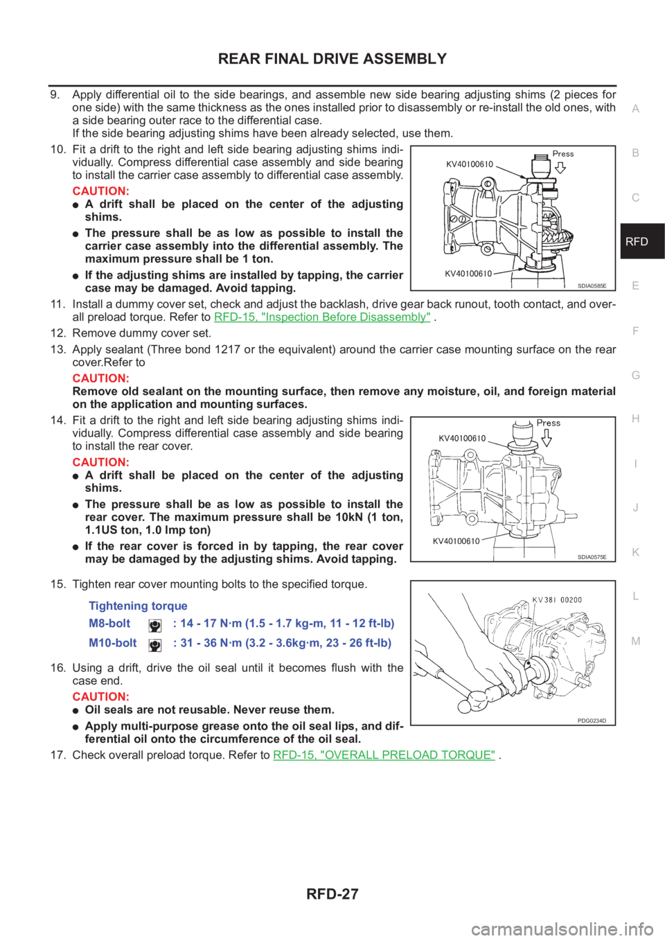
10. Fit a drift to the right and left side bearing adjusting shims indi-
vidually. Compress differential case assembly and side bearing
to install the carrier case assembly to differential case assembly.
CAUTION:
●A drift shall be placed on the center of the adjusting
shims.
●The pressure shall be as low as possible to install the
carrier case assembly into the differential assembly. The
maximum pressure shall be 1 ton.
●If the adjusting shims are installed by tapping, the carrier
case may be damaged. Avoid tapping.
11. Install a dummy cover set, check and adjust the backlash, drive gear back runout, tooth contact, and over-
all preload torque. Refer to RFD-15, "
Inspection Before Disassembly" .
12. Remove dummy cover set.
13. Apply sealant (Three bond 1217 or the equivalent) around the carrier case mounting surface on the rear
cover.Refer to
CAUTION:
Remove old sealant on the mounting surface, then remove any moisture, oil, and foreign material
on the application and mounting surfaces.
14. Fit a drift to the right and left side bearing adjusting shims indi-
vidually. Compress differential case assembly and side bearing
to install the rear cover.
CAUTION:
●A drift shall be placed on the center of the adjusting
shims.
●The pressure shall be as low as possible to install the
rear cover. The maximum pressure shall be 10kN (1 ton,
1.1US ton, 1.0 Imp ton)
●If the rear cover is forced in by tapping, the rear cover
may be damaged by the adjusting shims. Avoid tapping.
15. Tighten rear cover mounting bolts to the specified torque.
16. Using a drift, drive the oil seal until it becomes flush with the
case end.
CAUTION:
●Oil seals are not reusable. Never reuse them.
●Apply multi-purpose grease onto the oil seal lips, and dif-
ferential oil onto the circumference of the oil seal.
17. Check overall preload torque. Refer to RFD-15, "
OVERALL PRELOAD TORQUE" .
SDIA0585E
SDIA0575E
Tightening torque
M8-bolt : 14 - 17 N·m (1.5 - 1.7 kg-m, 11 - 12 ft-lb)
M10-bolt : 31 - 36 N·m (3.2 - 3.6kg·m, 23 - 26 ft-lb)
PDG0234D
Page 2704 of 3833
RFD-28
REAR FINAL DRIVE ASSEMBLY
Installation of Electronically Controlled Coupling Assembly
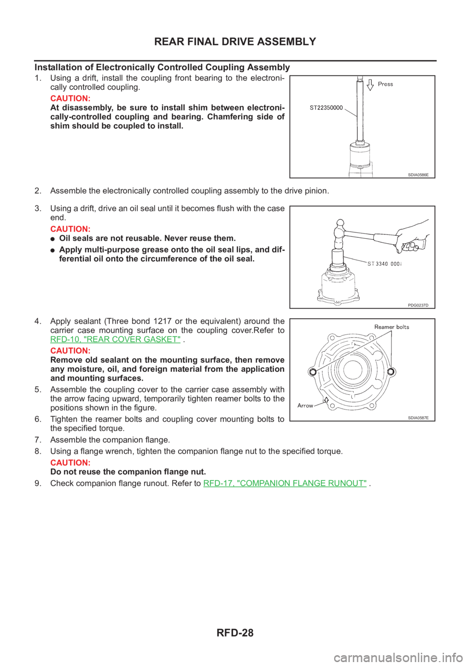
1. Using a drift, install the coupling front bearing to the electroni-
cally controlled coupling.
CAUTION:
At disassembly, be sure to install shim between electroni-
cally-controlled coupling and bearing. Chamfering side of
shim should be coupled to install.
2. Assemble the electronically controlled coupling assembly to the drive pinion.
3. Using a drift, drive an oil seal until it becomes flush with the case
end.
CAUTION:
●Oil seals are not reusable. Never reuse them.
●Apply multi-purpose grease onto the oil seal lips, and dif-
ferential oil onto the circumference of the oil seal.
4. Apply sealant (Three bond 1217 or the equivalent) around the
carrier case mounting surface on the coupling cover.Refer to
RFD-10, "
REAR COVER GASKET" .
CAUTION:
Remove old sealant on the mounting surface, then remove
any moisture, oil, and foreign material from the application
and mounting surfaces.
5. Assemble the coupling cover to the carrier case assembly with
the arrow facing upward, temporarily tighten reamer bolts to the
positions shown in the figure.
6. Tighten the reamer bolts and coupling cover mounting bolts to
the specified torque.
7. Assemble the companion flange.
8. Using a flange wrench, tighten the companion flange nut to the specified torque.
CAUTION:
Do not reuse the companion flange nut.
9. Check companion flange runout. Refer to RFD-17, "
COMPANION FLANGE RUNOUT" .
SDIA0586E
PDG0237D
SDIA0587E
Page 2708 of 3833
FSU-2
PRECAUTIONS
PRECAUTIONS
PFP:00001
CautionEES0006Z
●When installing rubber bushings, final tightening must be carried out under unladen conditions with tires
on flat, level ground. Oil will shorten the life of rubber bushings. Be sure to wipe off any spilled oil.
●“Unladen condition” means that fuel, coolant and lubricant are full and ready for drive. However, spare tire,
jack, and hand tools should be unloaded.
●After installing the removed suspension parts, always check wheel alignment and adjust if necessary.
●Replace the caulking nut with a new one. Install a new nut without wiping the oil off before tightening.
Page 2712 of 3833
FSU-6
FRONT SUSPENSION ASSEMBLY
On-Vehicle Inspection and Service
EES00072
LOOSENESS, BACKLASH AND DAMAGE OF MOUNTING PARTS AND CONNECTIONS
Lift vehicle and inspect the following:
●Check mounting point of each component for looseness, backlash and damage.
●Check lower ball joint end play.
1. Attach a dial gauge so that the contact rests on the brake caliper.
2. Set front wheels in a straight-ahead position. Do not depress brake pedal.
3. Measure axial endplay by placing an iron pry bar or something similar between transverse link and steer-
ing knuckle.
CAUTION:
Be careful not to damage ball joint boot.
4. If axial endplay is outside the standard, remove transverse link and check lower ball joint.
Wheel AlignmentEES00073
DESCRIPTION
●Measure wheel alignment under unladen conditions. “Unladen conditions” means that fuel, coolant, and
lubricant are full. However, spare tire, jack, and hand tools should be unloaded.
PRELIMINARY INSPECTION
1. Check the tires for improper air pressure and wear.
2. Check road wheels for runout.
3. Check wheel bearing axial endplay.
4. Check lower ball joint axial endplay.
5. Check strut operation.
6. Check each mounting point of axle and suspension for looseness and deformation.
7. Check each link and arm for cracks, deformation, and other damage.
8. Check the vehicle posture.
INSPECTION OF CAMBER, CASTER, AND KINGPIN INCLINATION ANGLES
● Camber, caster, and kingpin inclination angles cannot be adjusted.
●Before inspection, mount front wheels onto turning radius gauge. Mount rear wheels onto a stand that has
same height so the vehicle will remain horizontal.
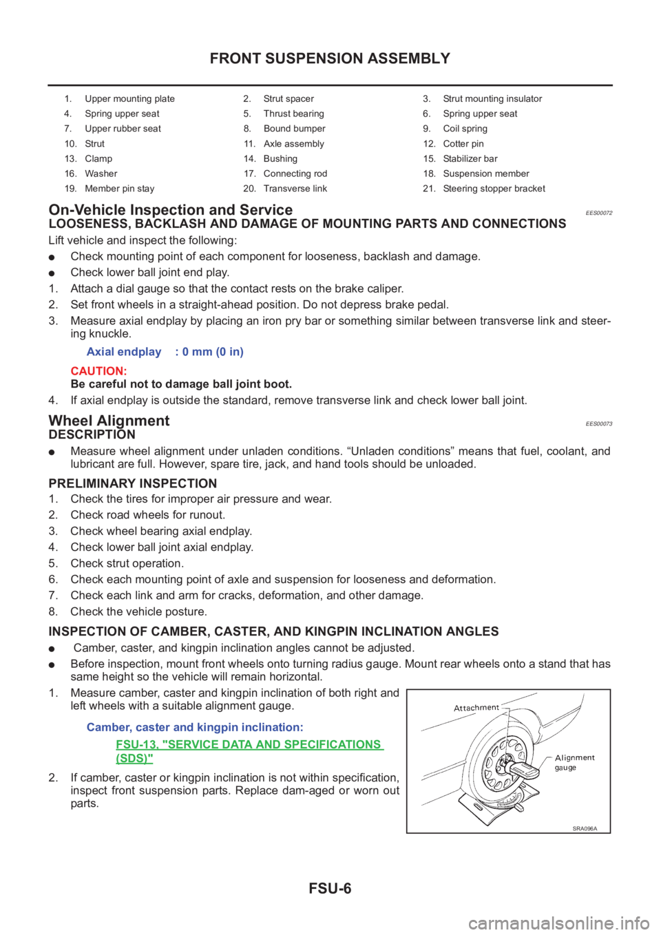
1. Measure camber, caster and kingpin inclination of both right and
left wheels with a suitable alignment gauge.
2. If camber, caster or kingpin inclination is not within specification,
inspect front suspension parts. Replace dam-aged or worn out
parts.
1. Upper mounting plate 2. Strut spacer 3. Strut mounting insulator
4. Spring upper seat 5. Thrust bearing 6. Spring upper seat
7. Upper rubber seat 8. Bound bumper 9. Coil spring
10. Strut 11. Axle assembly 12. Cotter pin
13. Clamp 14. Bushing 15. Stabilizer bar
16. Washer 17. Connecting rod 18. Suspension member
19. Member pin stay 20. Transverse link 21. Steering stopper bracket
Axial endplay : 0 mm (0 in)
Camber, caster and kingpin inclination:
FSU-13, "
SERVICE DATA AND SPECIFICATIONS
(SDS)"
SRA096A
Page 2714 of 3833
FSU-8
COIL SPRING AND SHOCK ABSORBER
COIL SPRING AND SHOCK ABSORBER
PFP:54302
Removal and InstallationEES00074
REMOVAL
1. Remove tires. Remove brake caliper and hung it aside.
CAUTION:
Avoid depressing brake pedal with brake caliper removed.
2. Remove electrical wires of ABS wheel speed sensor from strut.
3. Remove brake hose lock plate.
4. Remove mounting bolts and nuts securing steering knuckle to strut.
5. Remove mounting nuts on upper mounting plate and remove upper mounting plate and strut from vehicle.
INSTALLATION
●Refer to FSU-5, "Components" in “Front Suspension Assembly” for tightening torque. Tighten in the
reverse order of removal.
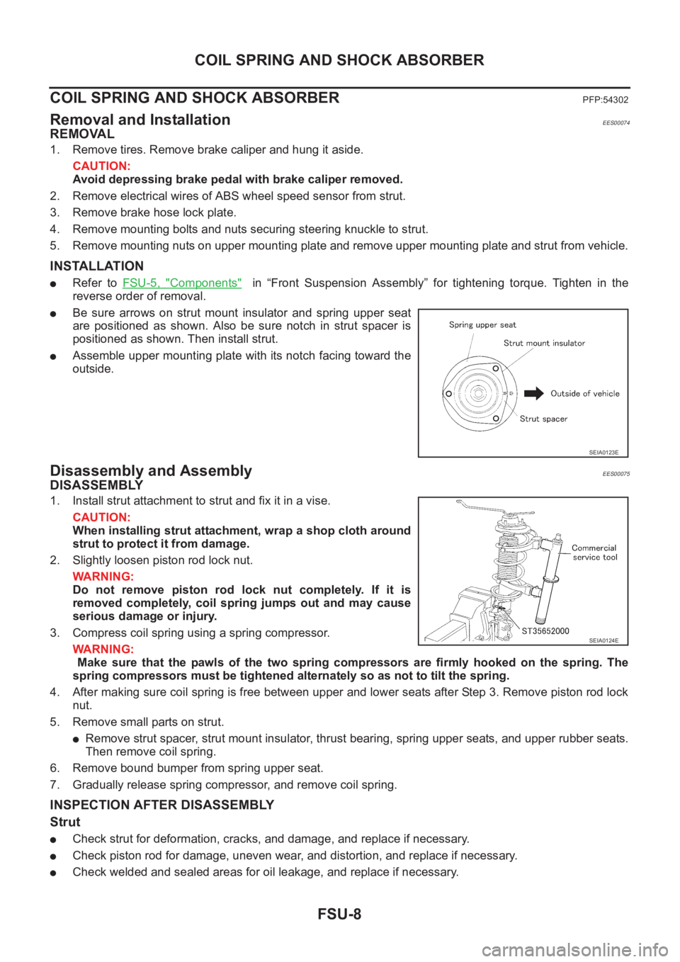
●Be sure arrows on strut mount insulator and spring upper seat
are positioned as shown. Also be sure notch in strut spacer is
positioned as shown. Then install strut.
●Assemble upper mounting plate with its notch facing toward the
outside.
Disassembly and AssemblyEES00075
DISASSEMBLY
1. Install strut attachment to strut and fix it in a vise.
CAUTION:
When installing strut attachment, wrap a shop cloth around
strut to protect it from damage.
2. Slightly loosen piston rod lock nut.
WARNING:
Do not remove piston rod lock nut completely. If it is
removed completely, coil spring jumps out and may cause
serious damage or injury.
3. Compress coil spring using a spring compressor.
WARNING:
Make sure that the pawls of the two spring compressors are firmly hooked on the spring. The
spring compressors must be tightened alternately so as not to tilt the spring.
4. After making sure coil spring is free between upper and lower seats after Step 3. Remove piston rod lock
nut.
5. Remove small parts on strut.
●Remove strut spacer, strut mount insulator, thrust bearing, spring upper seats, and upper rubber seats.
Then remove coil spring.
6. Remove bound bumper from spring upper seat.
7. Gradually release spring compressor, and remove coil spring.
INSPECTION AFTER DISASSEMBLY
Strut
●Check strut for deformation, cracks, and damage, and replace if necessary.
●Check piston rod for damage, uneven wear, and distortion, and replace if necessary.
●Check welded and sealed areas for oil leakage, and replace if necessary.
SEIA0123E
SEIA0124E
Page 2715 of 3833
COIL SPRING AND SHOCK ABSORBER
FSU-9
C
D
F
G
H
I
J
K
L
MA
B
FSU
Insulator and Rubber Parts
Check strut mount insulator for cracks and rubber parts for wear. Replace them if necessary.
Coil Spring
Check for cracks, wear, and damage, and replace if necessary.
ASSEMBLY
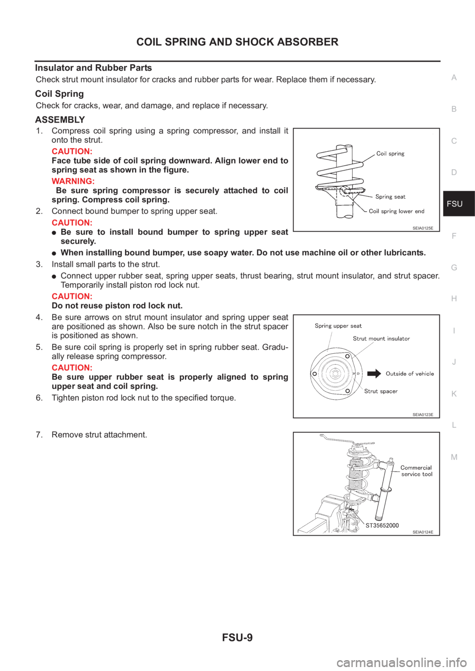
1. Compress coil spring using a spring compressor, and install it
onto the strut.
CAUTION:
Face tube side of coil spring downward. Align lower end to
spring seat as shown in the figure.
WARNING:
Be sure spring compressor is securely attached to coil
spring. Compress coil spring.
2. Connect bound bumper to spring upper seat.
CAUTION:
●Be sure to install bound bumper to spring upper seat
securely.
●When installing bound bumper, use soapy water. Do not use machine oil or other lubricants.
3. Install small parts to the strut.
●Connect upper rubber seat, spring upper seats, thrust bearing, strut mount insulator, and strut spacer.
Temporarily install piston rod lock nut.
CAUTION:
Do not reuse piston rod lock nut.
4. Be sure arrows on strut mount insulator and spring upper seat
are positioned as shown. Also be sure notch in the strut spacer
is positioned as shown.
5. Be sure coil spring is properly set in spring rubber seat. Gradu-
ally release spring compressor.
CAUTION:
Be sure upper rubber seat is properly aligned to spring
upper seat and coil spring.
6. Tighten piston rod lock nut to the specified torque.
7. Remove strut attachment.
SEIA0125E
SEIA0123E
SEIA0124E
Page 2722 of 3833
RSU-2
PRECAUTIONS
PRECAUTIONS
PFP:00001
CautionEES0007C
● Final tightening of bushings must be carried out under unladen condition with tires on the ground. Oil will
shorten life of bushings. Be sure to wipe off any spilled oil.
●“Unladen condition” means that fuel, coolant and lubricant are full and ready for drive. However, spare tire,
jack, and hand tools should be unloaded.
●After installing the removed suspension parts, always check wheel alignment and adjust if necessary.
●Replace the caulking nut with a new one. Install a new nut without wiping the oil off before tightening.