Page 2594 of 3833
AT-516
[ALL]
ASSEMBLY
12. Install O-ring on differential oil port of transmission case.
13. Install converter housing on transmission case.
●Apply locking sealant (Locktite #518) to mating surface of
converter housing.
●Tighten converter housing bolts to the specified torque.
Refer to AT-421, "
OVERHAUL" .
14. Install accumulator piston.
a. Check contact surface of accumulator piston for damage.
b. Install O-rings on accumulator piston.
●Apply ATF to O-rings.
SAT235F
SAT371H
SAT008F
SAT406DA
Accumulator piston O-rings:
Refer to AT-521, "
SERVICE DATA AND SPECIFICA-
TIONS (SDS)" .
SAT236FA
Page 2600 of 3833
![NISSAN X-TRAIL 2001 Service Repair Manual AT-522
[ALL]
SERVICE DATA AND SPECIFICATIONS (SDS)
Stall Revolution
ECS004MK
Line PressureECS004ML
Control ValvesECS004MM
CONTROL VALVE AND PLUG RETURN SPRINGS
For 85X23 model
Unit: mm (in)
*: Always NISSAN X-TRAIL 2001 Service Repair Manual AT-522
[ALL]
SERVICE DATA AND SPECIFICATIONS (SDS)
Stall Revolution
ECS004MK
Line PressureECS004ML
Control ValvesECS004MM
CONTROL VALVE AND PLUG RETURN SPRINGS
For 85X23 model
Unit: mm (in)
*: Always](/manual-img/5/57405/w960_57405-2599.png)
AT-522
[ALL]
SERVICE DATA AND SPECIFICATIONS (SDS)
Stall Revolution
ECS004MK
Line PressureECS004ML
Control ValvesECS004MM
CONTROL VALVE AND PLUG RETURN SPRINGS
For 85X23 model
Unit: mm (in)
*: Always check with the Parts Department for the latest parts information. EngineStall revolutio n
rpm
QR20DE 2,450 - 2,950
QR25DE 2,300 - 2,750
Engine speed
rpmLine pressure kPa (kg/cm2 , psi)
D, 2 and 1 positions R position
Idle 500 (5.1, 73) 778 (7.9, 113)
Stall 1,233 (12.6, 179) 1,918 (19.6, 278)
PartsItem
Part No.* Free length Outer diameter
Upper body23 Pilot valve spring 31742-3AX03 38.98 (1.535) 8.9 (0.350)
7 1-2 accumulator valve spring 31742-3AX00 20.5 (0.807) 6.95 (0.274)
28 1-2 accumulator piston spring 31742-85X02 55.60 (2.189) 19.6 (0.772)
33 1st reducing valve spring 31742-80X05 27.0 (1.063) 7.0 (0.276)
35 3-2 timing valve spring 31736-01X00 23.0 (0.906) 6.65 (0.262)
18 Overrun clutch reducing valve spring 31742-80X15 37.5 (1.476) 6.9 (0.272)
16 Torque converter relief valve spring 31742-80X07 31.0 (1.220) 9.0 (0.354)
11 Torque converter clutch control valve 31742-85X00 56.98 (2.243)6.5 (0.256)
3 Cooler check valve spring 31742-85X01 29.4 (1.157) 6.0 (0.236)
Lower body15 Pressure regulator valve spring 31742-80X13 45.0 (1.772) 15.0 (0.591)
20 Overrun clutch control valve spring 31762-80X00 21.7 (0.854) 7.0 (0.276)
24 Accumulator control valve spring 31742-80X02 22.0 (0.866) 6.5 (0.256)
29 Shift valve A spring 31762-80X00 21.7 (0.854) 7.0 (0.276)
32 Shuttle valve spring 31762-41X04 51.0 (2.008) 5.65 (0.222)
12 Shift valve B spring 31762-80X00 21.7 (0.854) 7.0 (0.276)
7
Pressure modifier valve spring31742-41X15 30.5 (1.201) 9.8 (0.386)
3 31742-80X16 32.0 (1.260) 6.9 (0.272)
— Oil cooler relief valve spring 31872-31X00 17.02 (0.670) 8.0 (0.315)
Page 2601 of 3833
![NISSAN X-TRAIL 2001 Service Repair Manual SERVICE DATA AND SPECIFICATIONS (SDS)
AT-523
[ALL]
D
E
F
G
H
I
J
K
L
MA
B
AT
For 85X64 model
Unit: mm (in)
*: Always check with the Parts Department for the latest parts information.
AccumulatorECS004 NISSAN X-TRAIL 2001 Service Repair Manual SERVICE DATA AND SPECIFICATIONS (SDS)
AT-523
[ALL]
D
E
F
G
H
I
J
K
L
MA
B
AT
For 85X64 model
Unit: mm (in)
*: Always check with the Parts Department for the latest parts information.
AccumulatorECS004](/manual-img/5/57405/w960_57405-2600.png)
SERVICE DATA AND SPECIFICATIONS (SDS)
AT-523
[ALL]
D
E
F
G
H
I
J
K
L
MA
B
AT
For 85X64 model
Unit: mm (in)
*: Always check with the Parts Department for the latest parts information.
AccumulatorECS004MN
O-RING
Unit: mm (in)
*: Always check with the Parts Department for the latest parts information. PartsItem
Part No.* Free length Outer diameter
Upper body23 Pilot valve spring 31742-3AX03 38.98 (1.535) 8.9 (0.350)
7 1-2 accumulator valve spring 31742-3AX00 20.5 (0.807) 6.95 (0.274)
28 1-2 accumulator piston spring 31742-3AX08 55.26 (2.176) 19.6 (0.772)
33 1st reducing valve spring 31742-80X05 27.0 (1.063) 7.0 (0.276)
35 3-2 timing valve spring 31736-01X00 23.29 (0.917) 6.65 (0.262)
18 Overrun clutch reducing valve spring 31742-80X15 37.5 (1.476) 6.9 (0.272)
16 Torque converter relief valve spring 31742-80X07 31.0 (1.220) 9.0 (0.354)
11 Torque converter clutch control valve spring 31742-85X00 56.98 (2.243) 6.5 (0.256)
3 Cooler check valve spring 31742-85X01 29.4 (1.157) 6.0 (0.236)
Lower body15 Pressure regulator valve spring 31742-80X13 45.0 (1.772) 15.0 (0.591)
20 Overrun clutch control valve spring 31762-80X00 21.7 (0.854) 7.0 (0.276)
24 Accumulator control valve spring 31742-80X02 22.0 (0.866) 6.5 (0.256)
29 Shift valve A spring 31762-80X00 21.7 (0.854) 7.0 (0.276)
32 Shuttle valve spring 31762-41X04 51.0 (2.008) 5.65 (0.222)
12 Shift valve B spring 31762-80X00 21.7 (0.854) 7.0 (0.276)
7
Pressure modifier valve spring31742-41X15 30.5 (1.201) 9.8 (0.386)
3 31742-80X16 32.0 (1.260) 6.9 (0.272)
— Oil cooler relief valve spring 31872-31X00 17.02 (0.670) 8.0 (0.315)
Accumulator Part No.*Inner diameter
(Small)Part No.*Inner diameter
(Large)
Servo release accumulator 31526 41X03 26.9 (1.059) 31526 41X02 44.2 (1.740)
N-D accumulator 31526 31X08 34.6 (1.362) 31672 21X00 39.4 (1.551)
Page 2605 of 3833
![NISSAN X-TRAIL 2001 Service Repair Manual SERVICE DATA AND SPECIFICATIONS (SDS)
AT-527
[ALL]
D
E
F
G
H
I
J
K
L
MA
B
AT
DIFFERENTIAL SIDE GEAR THRUST WASHERS
*: Always check with the Parts Department for the latest parts information.
DIFFERENT NISSAN X-TRAIL 2001 Service Repair Manual SERVICE DATA AND SPECIFICATIONS (SDS)
AT-527
[ALL]
D
E
F
G
H
I
J
K
L
MA
B
AT
DIFFERENTIAL SIDE GEAR THRUST WASHERS
*: Always check with the Parts Department for the latest parts information.
DIFFERENT](/manual-img/5/57405/w960_57405-2604.png)
SERVICE DATA AND SPECIFICATIONS (SDS)
AT-527
[ALL]
D
E
F
G
H
I
J
K
L
MA
B
AT
DIFFERENTIAL SIDE GEAR THRUST WASHERS
*: Always check with the Parts Department for the latest parts information.
DIFFERENTIAL SIDE BEARING PRELOAD ADJUSTING SHIMS
*: Always check with the Parts Department for the latest parts information.
BEARING PRELOAD
TURNING TORQUE
Planetary Carrier and Oil PumpECS004MQ
PLANETARY CARRIER
OIL PUMP
*: Always check with the Parts Department for the latest parts information. Thickness mm (in) Part number*
0.75 (0.0295)
0.80 (0.0315)
0.85 (0.0335)
0.90 (0.0354)
0.95 (0.0374)38424-81X00
38424-81X01
38424-81X02
38424-81X03
38424-81X04
Thickness mm (in) Part number*
0.48 (0.0189)
0.52 (0.0205)
0.56 (0.0220)
0.60 (0.0236)
0.64 (0.0252)
0.68 (0.0268)
0.72 (0.0283)
0.76 (0.0299)
0.80 (0.0315)
0.84 (0.0331)
0.88 (0.0346)
0.92 (0.0362)31438-80X00
31438-80X01
31438-80X02
31438-80X03
31438-80X04
31438-80X05
31438-80X06
31438-80X07
31438-80X08
31438-80X09
31438-80X10
31438-80X11
Differential side bearing preload mm (in) 0.05 - 0.09 (0.0020 - 0.0035)
Turning torque of final drive assembly N·m (kg-cm, in-lb) 0.78 - 1.37 (8.0 - 14.0, 6.9 - 12.2)
Clearance between planetary carrier
and pinion washer mm (in)Standard 0.20 - 0.70 (0.0079 - 0.0276)
Allowable limit 0.80 (0.0315)
Oil pump side clearance mm (in) 0.030 - 0.050 (0.0012 - 0.0020)
Thickness of inner gears and outer gearsInner gear
Thickness mm (in) Part number*
11.99 - 12.0 (0.4720 - 0.4724)
11.98 - 11.99 (0.4717 - 0.4720)
11.97 - 11.98 (0.4713 - 0.4717)31346-80X00
31346-80X01
31346-80X02
Outer gear
Thickness mm (in) Part number*
11.99 - 12.0 (0.4720 - 0.4724)
11.98 - 11.99 (0.4717 - 0.4720)
11.97 - 11.98 (0.4713 - 0.4717)31347-80X00
31347-80X01
31347-80X02
Clearance between oil pump
housing and outer gear mm
(in)Standard 0.111 - 0.181 (0.0044 - 0.0071)
Allowable limit 0.181 (0.0071)
Oil pump cover seal ring
clearance mm (in)Standard 0.1 - 0.25 (0.0039 - 0.0098)
Allowable limit 0.25 (0.0098)
Page 2613 of 3833

PRECAUTIONS
TF-3
C
E
F
G
H
I
J
K
L
MA
B
TF
PRECAUTIONSPFP:00001
CautionEDS0004O
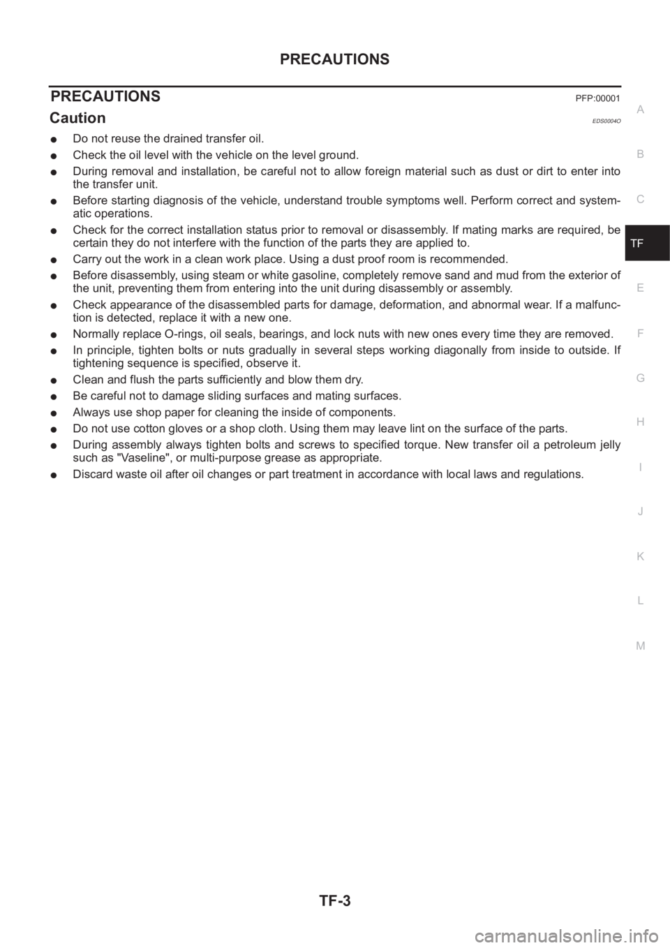
●Do not reuse the drained transfer oil.
●Check the oil level with the vehicle on the level ground.
●During removal and installation, be careful not to allow foreign material such as dust or dirt to enter into
the transfer unit.
●Before starting diagnosis of the vehicle, understand trouble symptoms well. Perform correct and system-
atic operations.
●Check for the correct installation status prior to removal or disassembly. If mating marks are required, be
certain they do not interfere with the function of the parts they are applied to.
●Carry out the work in a clean work place. Using a dust proof room is recommended.
●Before disassembly, using steam or white gasoline, completely remove sand and mud from the exterior of
the unit, preventing them from entering into the unit during disassembly or assembly.
●Check appearance of the disassembled parts for damage, deformation, and abnormal wear. If a malfunc-
tion is detected, replace it with a new one.
●Normally replace O-rings, oil seals, bearings, and lock nuts with new ones every time they are removed.
●In principle, tighten bolts or nuts gradually in several steps working diagonally from inside to outside. If
tightening sequence is specified, observe it.
●Clean and flush the parts sufficiently and blow them dry.
●Be careful not to damage sliding surfaces and mating surfaces.
●Always use shop paper for cleaning the inside of components.
●Do not use cotton gloves or a shop cloth. Using them may leave lint on the surface of the parts.
●During assembly always tighten bolts and screws to specified torque. New transfer oil a petroleum jelly
such as "Vaseline", or multi-purpose grease as appropriate.
●Discard waste oil after oil changes or part treatment in accordance with local laws and regulations.
Page 2617 of 3833
NOISE, VIBRATION, AND HARSHNESS (NVH) TROUBLESHOOTING
TF-7
C
E
F
G
H
I
J
K
L
MA
B
TF
NOISE, VIBRATION, AND HARSHNESS (NVH) TROUBLESHOOTINGPFP:00003
NVH Troubleshooting ChartEDS000I4
Use the chart below to help you find the cause of the problem.The numbers indicate the order of the inspec-
tion. If necessary, repair or replace these parts.
Reference page
Refer to MA section("Checking Transfer Fluid"
("CHASSIS AND BODY MAINTENANCE").
TF-13
TF-13TF-22TF-22
Possible cause and Suspected parts
FLUID (Level low)
FLUID (Wrong)
FLUID (Level too high)
LIQUID GASKET (Damaged)
OIL SEAL (Worn or damaged)
GEAR (Worn or damaged)
BEARING (Worn or damaged)
SymptomNoise 1 2 3 3
Fluid leakage 3 1 2 2
jumps out of gear 1
Page 2618 of 3833

TF-8
TRANSFER FLUID
TRANSFER FLUID
PFP:KLD30
ReplacementEDS0004Q
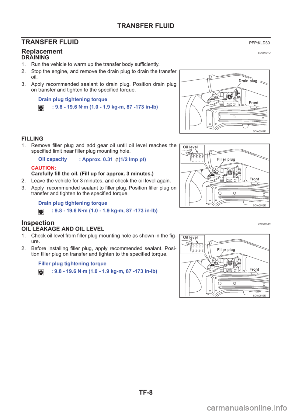
DRAINING
1. Run the vehicle to warm up the transfer body sufficiently.
2. Stop the engine, and remove the drain plug to drain the transfer
oil.
3. Apply recommended sealant to drain plug. Position drain plug
on transfer and tighten to the specified torque.
FILLING
1. Remove filler plug and add gear oil until oil level reaches the
specified limit near filler plug mounting hole.
CAUTION:
Carefully fill the oil. (Fill up for approx. 3 minutes.)
2. Leave the vehicle for 3 minutes, and check the oil level again.
3. Apply recommended sealant to filler plug. Position filler plug on
transfer and tighten to the specified torque.
InspectionEDS0004R
OIL LEAKAGE AND OIL LEVEL
1. Check oil level from filler plug mounting hole as shown in the fig-
ure.
2. Before installing filler plug, apply recommended sealant. Posi-
tion filler plug on transfer and tighten to the specified torque. Drain plug tightening torque
: 9.8 - 19.6 N·m (1.0 - 1.9 kg-m, 87 -173 in-lb)
SDIA0512E
Oil capacity
: Approx. 0.31 (1/2 lmp pt)
Drain plug tightening torque
: 9.8 - 19.6 N·m (1.0 - 1.9 kg-m, 87 -173 in-lb)
SDIA0513E
Filler plug tightening torque
: 9.8 - 19.6 N·m (1.0 - 1.9 kg-m, 87 -173 in-lb)
SDIA0513E
Page 2619 of 3833
SIDE OIL SEAL
TF-9
C
E
F
G
H
I
J
K
L
MA
B
TF
SIDE OIL SEALPFP:33142
Removal and InstallationEDS0004S
REMOVAL
1. Remove the drive shaft.
2. Remove the side shaft.
3. Remove oil seal with a flat-bladed screwdriver.
CAUTION:
Be careful not to damage the adapter case.
INSTALLATION
1. Apply multi-purpose grease to oil seal lips. As shown in the fig-
ure, using a drift, install the oil seal so that it becomes flush with
the case end surface.
CAUTION:
●Discard old oil seals; replace with new ones.
●When installing, do not incline the oil seal.
2. Install the side shaft.
CAUTION:
Be careful not to damage the oil seal lips.
3. Install the drive shaft.
4. Check oil level.
TFB0202D
SDIA0515E