Page 2950 of 3833
FAX-2
PRECAUTIONS
PRECAUTIONS
PFP:00001
CautionEDS0005P
●When installing rubber parts, final tightening must be carried out under unladen condition* with tires on
ground.
●Oil will shorten the life of rubber bushes. Be sure to wipe off any spilled oil.
*: Fuel, radiator coolant and engine oil full. Spare tire, jack, hand tools and mats in designated positions.
●After installing removed suspension parts, check wheel alignment and adjust if necessary.
Observe the following precautions when disassembling and servicing drive shaft.
●Perform work in a location which is as dust-free and dirt-free as possible.
●Before disassembling and servicing, clean the outside of parts.
●Disassembly and service location must be taken to prevent the entry of foreign objects.
●Disassembled parts must be carefully reassembled in the correct order. If work is interrupted, a clean
cover must be placed over parts.
●Paper shop cloths must be used. Fabric shop cloths must not be used because of the danger of lint adher-
ing to parts.
●Disassembled parts (except for rubber parts) should be cleaned with kerosene which shall be removed by
blowing with air or wiping with paper shop cloths.
Page 2968 of 3833
RAX-2
PRECAUTIONS
PRECAUTIONS
PFP:00001
CautionEDS00060
●When installing rubber parts, final tightening must be carried out under unladen condition* with tires on
ground.
*: Fuel, radiator coolant and engine oil full. Spare tire, jack, hand tools and mats in designated positions.
●After installing removed suspension parts, check wheel alignment and adjust if necessary.
Observe the following precautions when disassembling and servicing drive shaft.
●Perform work in a location which is as dust-free and dirt-free as possible.
●Before disassembling and servicing, clean the outside of parts.
●The disassembly and service location must be clean. Care must be taken to prevent parts from becoming
dirty and to prevent the entry of foreign objects.
●Disassembled parts must be carefully reassembled in the correct order. If work is interrupted, a clean
cover must be placed over parts.
●Paper shop cloths must be used. Fabric shop cloths must not be used because of the danger of lint adher-
ing to parts.
●Disassembled parts (except for rubber parts) should be cleaned with kerosene which shall be removed by
blowing with air or wiping with paper shop cloths.
Page 3305 of 3833
AIR CONDITIONER CONTROL
ATC-29
C
D
E
F
G
H
I
K
L
MA
B
AT C
FAN SPEED CONTROL
Blower speed is automatically controlled based on temperature setting, ambient temperature, in-vehicle tem-
perature, intake temperature, amount of sunload and air mix door position.
With FAN switch set to AUTO, the blower motor starts to gradually increase air flow volume.
When engine coolant temperature is low, the blower motor operation is delayed to prevent cool air from flow-
ing.
INTAKE DOOR CONTROL
The intake doors are automatically controlled by: The temperature setting, ambient temperature, in-vehicle
temperature, intake temperature, amount of sunload and ON-OFF operation of the compressor.
OUTLET DOOR CONTROL
The outlet door is automatically controlled by: The temperature setting, ambient temperature, in-vehicle tem-
perature, intake temperature and amount of sunload.
MAGNET CLUTCH CONTROL
The ECM controls compressor operation using input signals from the throttle position sensor and auto ampli-
fier.
SELF-DIAGNOSTIC SYSTEM
The self-diagnostic system is built into the auto amplifier (LCU) to quickly locate the cause of malfunctions.
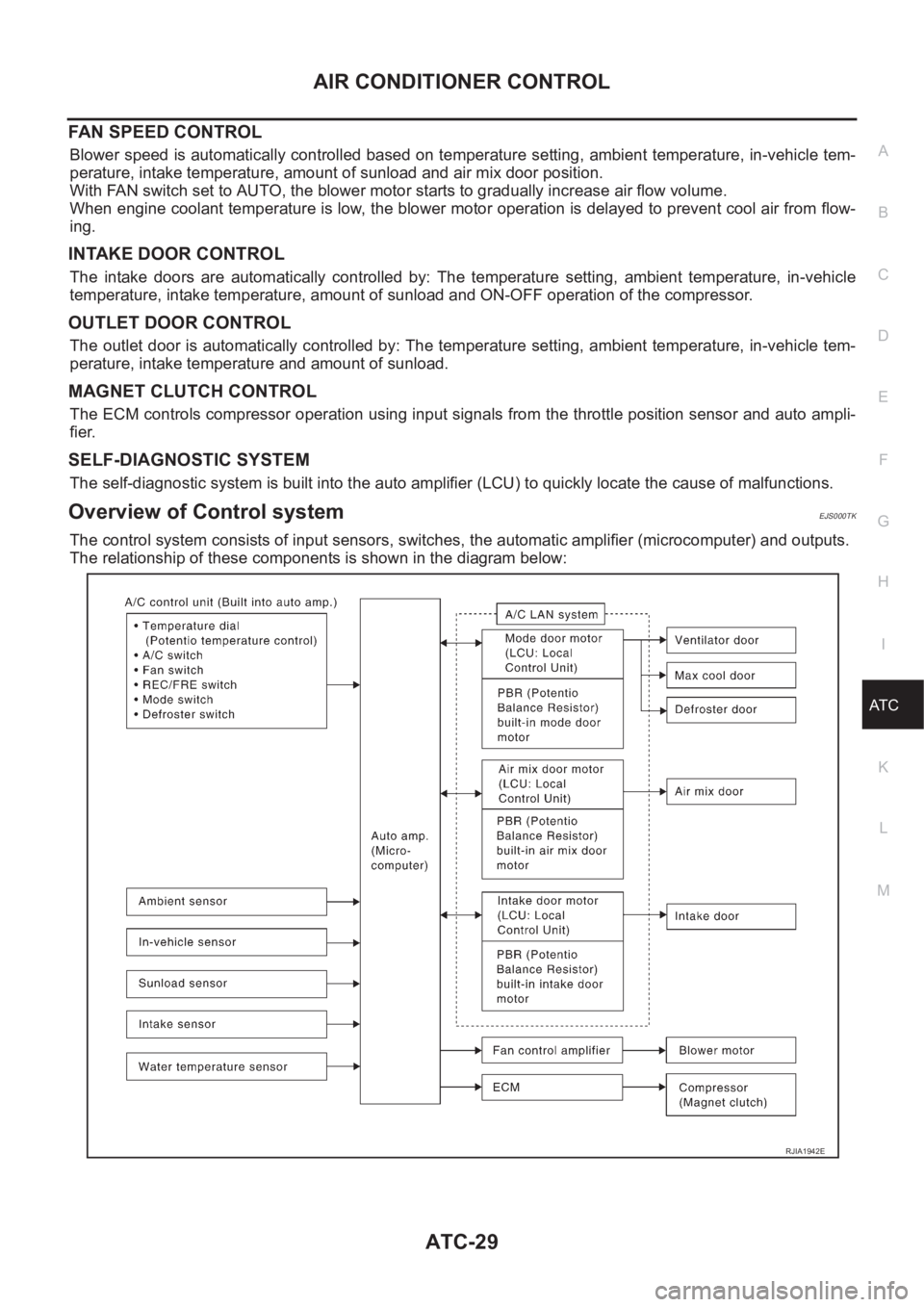
Overview of Control systemEJS000TK
The control system consists of input sensors, switches, the automatic amplifier (microcomputer) and outputs.
The relationship of these components is shown in the diagram below:
RJIA1942E
Page 3348 of 3833
ATC-72
TROUBLE DIAGNOSIS
SYSTEM DESCRIPTION
Component Parts
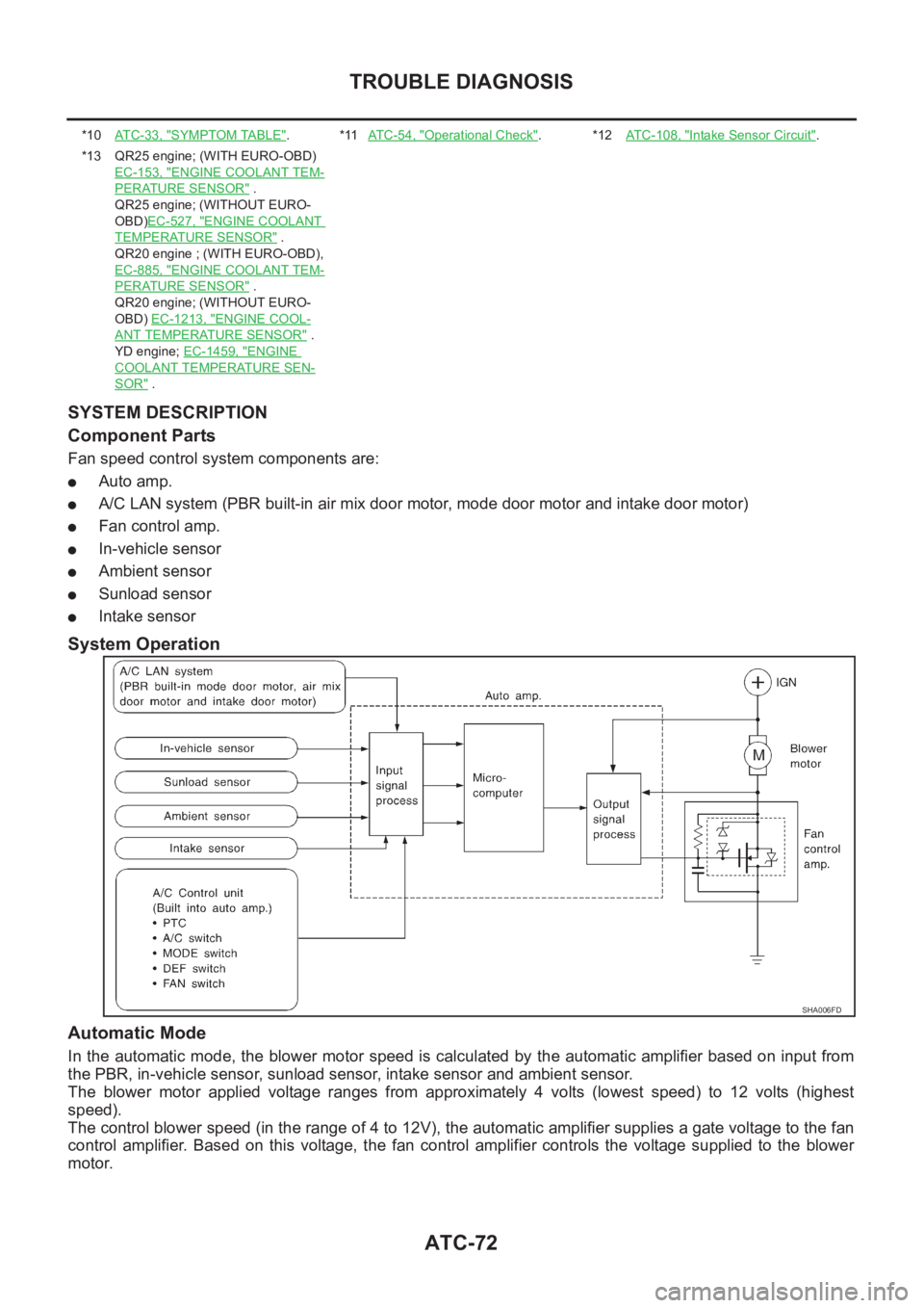
Fan speed control system components are:
●Auto amp.
●A/C LAN system (PBR built-in air mix door motor, mode door motor and intake door motor)
●Fan control amp.
●In-vehicle sensor
●Ambient sensor
●Sunload sensor
●Intake sensor
System Operation
Automatic Mode
In the automatic mode, the blower motor speed is calculated by the automatic amplifier based on input from
the PBR, in-vehicle sensor, sunload sensor, intake sensor and ambient sensor.
The blower motor applied voltage ranges from approximately 4 volts (lowest speed) to 12 volts (highest
speed).
The control blower speed (in the range of 4 to 12V), the automatic amplifier supplies a gate voltage to the fan
control amplifier. Based on this voltage, the fan control amplifier controls the voltage supplied to the blower
motor.
*10AT C - 3 3 , "SYMPTOM TABLE".*11AT C - 5 4 , "Operational Check".*12ATC-108, "Intake Sensor Circuit".
*13 QR25 engine; (WITH EURO-OBD)
EC-153, "
ENGINE COOLANT TEM-
PERATURE SENSOR" .
QR25 engine; (WITHOUT EURO-
OBD)EC-527, "
ENGINE COOLANT
TEMPERATURE SENSOR" .
QR20 engine ; (WITH EURO-OBD),
EC-885, "
ENGINE COOLANT TEM-
PERATURE SENSOR" .
QR20 engine; (WITHOUT EURO-
OBD) EC-1213, "
ENGINE COOL-
ANT TEMPERATURE SENSOR" .
YD engine; EC-1459, "
ENGINE
COOLANT TEMPERATURE SEN-
SOR" .
SHA006FD
Page 3349 of 3833
TROUBLE DIAGNOSIS
ATC-73
C
D
E
F
G
H
I
K
L
MA
B
AT C
Starting Fan Speed Control
Start Up From COLD SOAK Condition (Automatic mode)
In a cold start up condition where the engine coolant temperature is below 56°C, the blower will not operate for
a short period of time (up to 150 seconds). The exact start delay time varies depending on the ambient and
engine coolant temperature.
In the most extreme case (very low ambient) the blower starting delay will be 150 seconds as described
above. After this delay, the blower will operate at low speed until the engine coolant temperature rises above
56°C, at which time the blower speed will increase to the objective speed.
Start Up From Normal or HOT SOAK Condition (Automatic mode)
The blower will begin operation momentarily after the A/C button is pushed. The blower speed will gradually
rise to the objective speed over a time period of 3 seconds or less (actual time depends on the objective
blower speed).
Page 3372 of 3833
ATC-96
TROUBLE DIAGNOSIS
*10 QR25 engine; (WITH EURO-OBD)
EC-153, "
ENGINE COOLANT TEM-
PERATURE SENSOR" .
QR25 engine; (WITHOOUT EUR-
OBD)EC-527, "
ENGINE COOLANT
TEMPERATURE SENSOR" .
QR20 engine; (WITH EURO-OBD)
EC-885, "
ENGINE COOLANT TEM-
PERATURE SENSOR" .
QR20 engine; (WITHOUT EURO-
OBD)EC-1213, "
ENGINE COOLANT
TEMPERATURE SENSOR" .
YD engine; EC-1508, "
SYSTEM
DESCRIPTION" .*11 QR engine; CO-9, "
Changing Engine
Coolant" .
YD engine; CO-29, "
Changing
Engine Coolant" .*12 QR engine; CO-9, "
Changing Engine
Coolant" .
YD engine; CO-29, "
Changing
Engine Coolant" .
*13 QR engine; CO-12, "
Checking Radi-
ator Cap" .
YD engine; CO-33, "
Checking Radi-
ator Cap" .
Page 3398 of 3833
ATC-122
HEATER & COOLING UNIT ASSEMBLY
HEATER & COOLING UNIT ASSEMBLY
PFP:27110
Removal and InstallationEJS000UT
REMOVAL
1. Discharge refrigerant from A/C system.
2. Drain coolant from cooling system. Refer to CO-9, "
Changing
Engine Coolant" for QR engine, CO-29, "Changing Engine
Coolant" for YD engine.
3. Disconnect two heater hoses from heater core pipe.
4. Remove the instrument panel.
5. Remove the blower unit.
6. Remove clips of vehicle harness from steering member.
7. Remove the instrument stay.
8. Remove the bolts from heater & cooling unit.
9. Remove the steering member.
10. Remove the heater & cooling unit.
RJIA0060E
RJIA0061E
RJIA0062E
RJIA0063E
Page 3399 of 3833
HEATER & COOLING UNIT ASSEMBLY
ATC-123
C
D
E
F
G
H
I
K
L
MA
B
AT C
INSTALLATION
1. Installation is basically the reverse order of removal.
NOTE:
When filling radiator with coolant, refer to CO-9, "
Changing Engine Coolant" for QR engine, CO-29, "Chang-
ing Engine Coolant" for YD engine.
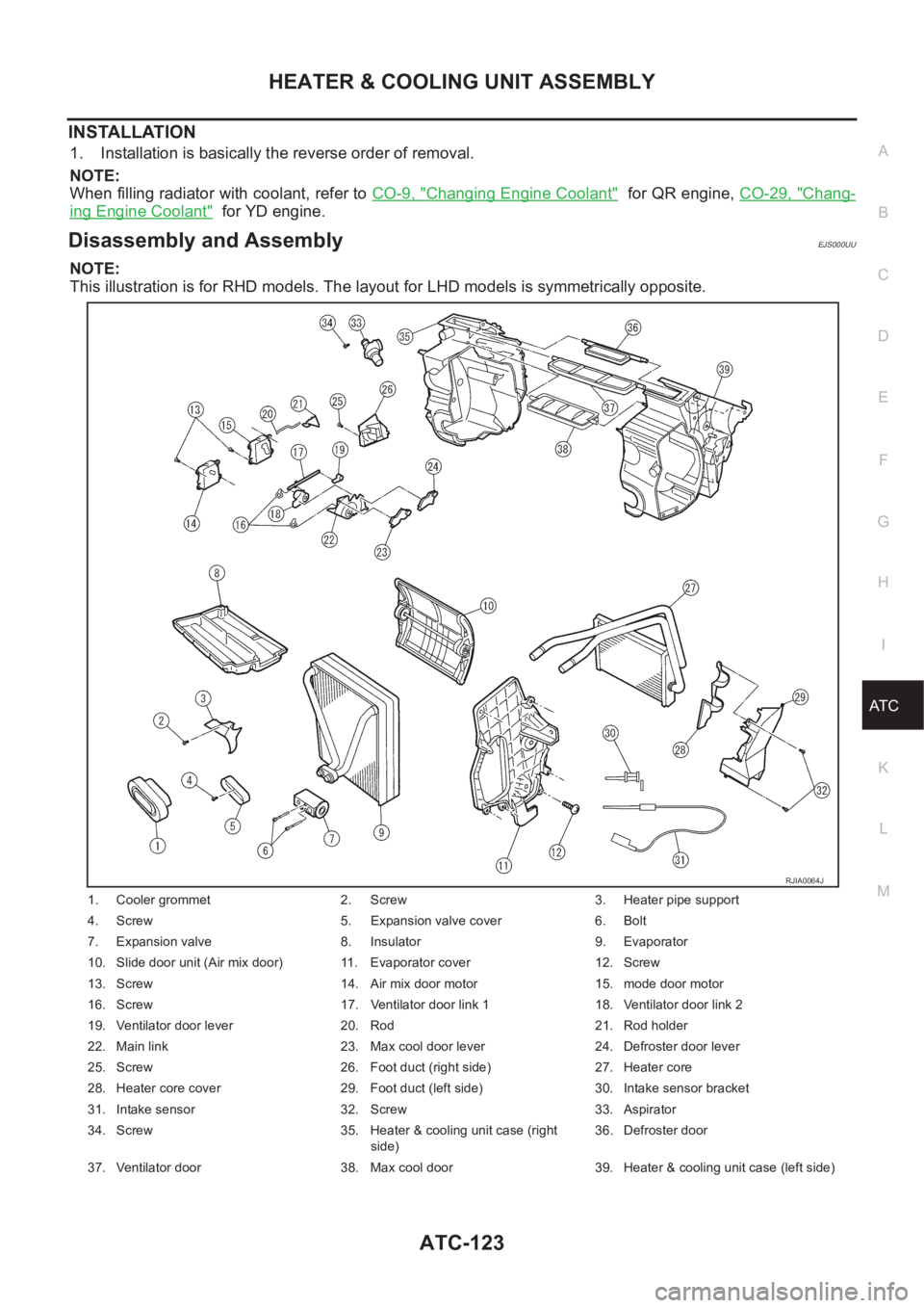
Disassembly and AssemblyEJS000UU
NOTE:
This illustration is for RHD models. The layout for LHD models is symmetrically opposite.
1. Cooler grommet 2. Screw 3. Heater pipe support
4. Screw 5. Expansion valve cover 6. Bolt
7. Expansion valve 8. Insulator 9. Evaporator
10. Slide door unit (Air mix door) 11. Evaporator cover 12. Screw
13. Screw 14. Air mix door motor 15. mode door motor
16. Screw 17. Ventilator door link 1 18. Ventilator door link 2
19. Ventilator door lever 20. Rod 21. Rod holder
22. Main link 23. Max cool door lever 24. Defroster door lever
25. Screw 26. Foot duct (right side) 27. Heater core
28. Heater core cover 29. Foot duct (left side) 30. Intake sensor bracket
31. Intake sensor 32. Screw 33. Aspirator
34. Screw 35. Heater & cooling unit case (right
side)36. Defroster door
37. Ventilator door 38. Max cool door 39. Heater & cooling unit case (left side)
RJIA0064J