2001 NISSAN X-TRAIL coolant
[x] Cancel search: coolantPage 3445 of 3833
TROUBLE DIAGNOSIS
MTC-19
C
D
E
F
G
H
I
K
L
MA
B
MTC
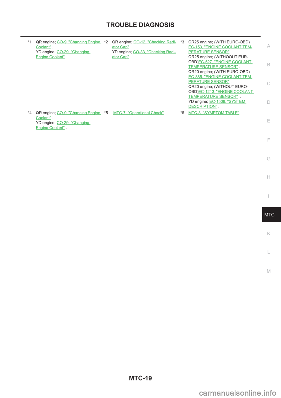
*1 QR engine; CO-9, "Changing Engine
Coolant" .
YD engine; CO-29, "
Changing
Engine Coolant" .*2 QR engine; CO-12, "
Checking Radi-
ator Cap"
YD engine; CO-33, "Checking Radi-
ator Cap" .*3 QR25 engine; (WITH EURO-OBD)
EC-153, "
ENGINE COOLANT TEM-
PERATURE SENSOR" .
QR25 engine; (WITHOOUT EUR-
OBD)EC-527, "
ENGINE COOLANT
TEMPERATURE SENSOR" .
QR20 engine; (WITH EURO-OBD)
EC-885, "
ENGINE COOLANT TEM-
PERATURE SENSOR" .
QR20 engine; (WITHOUT EURO-
OBD)EC-1213, "
ENGINE COOLANT
TEMPERATURE SENSOR" .
YD engine; EC-1508, "
SYSTEM
DESCRIPTION" .
*4 QR engine; CO-9, "
Changing Engine
Coolant" .
YD engine; CO-29, "
Changing
Engine Coolant" .*5 MTC-7, "
Operational Check"*6MTC-3, "SYMPTOM TABLE"
Page 3450 of 3833
MTC-24
HEATER UNIT
HEATER UNIT
PFP:27100
Removal and InstallationEJS001F9
REMOVAL
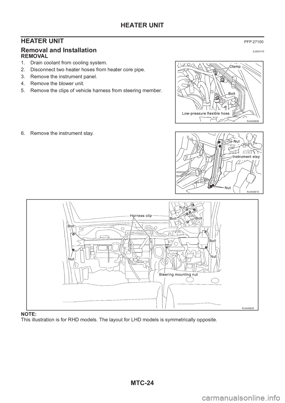
1. Drain coolant from cooling system.
2. Disconnect two heater hoses from heater core pipe.
3. Remove the instrument panel.
4. Remove the blower unit.
5. Remove the clips of vehicle harness from steering member.
6. Remove the instrument stay.
NOTE:
This illustration is for RHD models. The layout for LHD models is symmetrically opposite.
RJIA0060E
RJIA0061E
RJIA0062E
Page 3451 of 3833
HEATER UNIT
MTC-25
C
D
E
F
G
H
I
K
L
MA
B
MTC
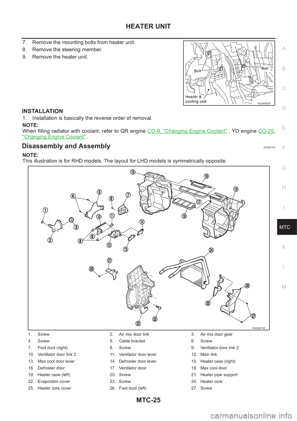
7. Remove the mounting bolts from heater unit.
8. Remove the steering member.
9. Remove the heater unit.
INSTALLATION
1. Installation is basically the reverse order of removal.
NOTE:
When filling radiator with coolant, refer to QR engine CO-9, "
Changing Engine Coolant" , YD engine CO-29,
"Changing Engine Coolant" .
Disassembly and AssemblyEJS001FA
NOTE:
This illustration is for RHD models. The layout for LHD models is symmetrically opposite.
RJIA0063E
1. Screw 2. Air mix door link 3. Air mix door gear
4. Screw 5. Cable bracket 6. Screw
7. Foot duct (right) 8. Screw 9. Ventilator door link 2
10. Ventilator door link 2 11. Ventilator door lever 12. Main link
13. Max cool door lever 14. Defroster door lever 15. Heater case (right)
16. Defroster door 17. Ventilator door 18. Max cool door
19. Heater case (left) 20. Screw 21. Heater pipe support
22. Evaporator cover 23. Screw 24. Heater core
25. Heater core cover 26. Foot duct (left) 27. Screw
RJIA0613E
Page 3496 of 3833
LT-6
HEADLAMP
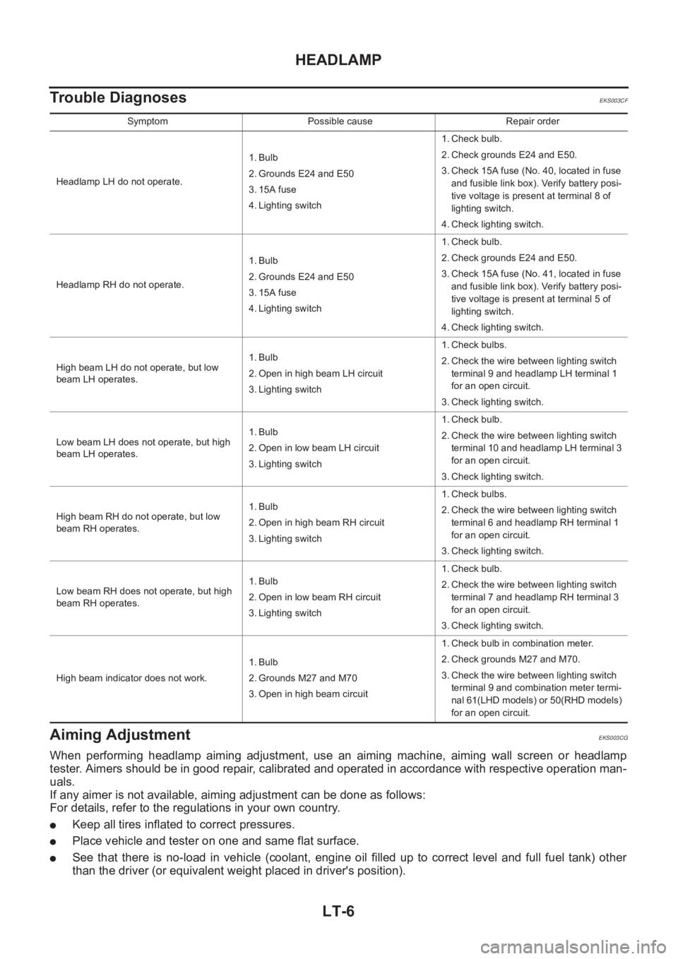
Trouble Diagnoses
EKS003CF
Aiming Adjustment EKS003CG
When performing headlamp aiming adjustment, use an aiming machine, aiming wall screen or headlamp
tester. Aimers should be in good repair, calibrated and operated in accordance with respective operation man-
uals.
If any aimer is not available, aiming adjustment can be done as follows:
For details, refer to the regulations in your own country.
●Keep all tires inflated to correct pressures.
●Place vehicle and tester on one and same flat surface.
●See that there is no-load in vehicle (coolant, engine oil filled up to correct level and full fuel tank) other
than the driver (or equivalent weight placed in driver's position).
Symptom Possible cause Repair order
Headlamp LH do not operate.1. Bulb
2. Grounds E24 and E50
3. 15A fuse
4. Lighting switch1. Check bulb.
2. Check grounds E24 and E50.
3. Check 15A fuse (No. 40, located in fuse
and fusible link box). Verify battery posi-
tive voltage is present at terminal 8 of
lighting switch.
4. Check lighting switch.
Headlamp RH do not operate.1. Bulb
2. Grounds E24 and E50
3. 15A fuse
4. Lighting switch1. Check bulb.
2. Check grounds E24 and E50.
3. Check 15A fuse (No. 41, located in fuse
and fusible link box). Verify battery posi-
tive voltage is present at terminal 5 of
lighting switch.
4. Check lighting switch.
High beam LH do not operate, but low
beam LH operates.1. Bulb
2. Open in high beam LH circuit
3. Lighting switch1. Check bulbs.
2. Check the wire between lighting switch
terminal 9 and headlamp LH terminal 1
for an open circuit.
3. Check lighting switch.
Low beam LH does not operate, but high
beam LH operates.1. Bulb
2. Open in low beam LH circuit
3. Lighting switch1. Check bulb.
2. Check the wire between lighting switch
terminal 10 and headlamp LH terminal 3
for an open circuit.
3. Check lighting switch.
High beam RH do not operate, but low
beam RH operates.1. Bulb
2. Open in high beam RH circuit
3. Lighting switch1. Check bulbs.
2. Check the wire between lighting switch
terminal 6 and headlamp RH terminal 1
for an open circuit.
3. Check lighting switch.
Low beam RH does not operate, but high
beam RH operates.1. Bulb
2. Open in low beam RH circuit
3. Lighting switch1. Check bulb.
2. Check the wire between lighting switch
terminal 7 and headlamp RH terminal 3
for an open circuit.
3. Check lighting switch.
High beam indicator does not work.1. Bulb
2. Grounds M27 and M70
3. Open in high beam circuit1. Check bulb in combination meter.
2. Check grounds M27 and M70.
3. Check the wire between lighting switch
terminal 9 and combination meter termi-
nal 61(LHD models) or 50(RHD models)
for an open circuit.
Page 3562 of 3833
DI-4
COMBINATION METERS (LHD MODELS)
COMBINATION METERS (LHD MODELS)
PFP:24810
System DescriptionEKS002Z7
UNIFIED CONTROL METER
●Speedometer, odo/trip meter, tachometer, fuel gauge and water temperature gauge are controlled totally
by control unit built-in combination meter.
●Digital meter is adopted for odo/trip meter.*
*The record of the odo meter is kept even if the battery cable is disconnected. The record of the trip meter
is erased when the battery cable is disconnected.
●Odo/trip meter segment can be checked in diagnosis mode.
●Meter/gauge can be checked in diagnosis mode.
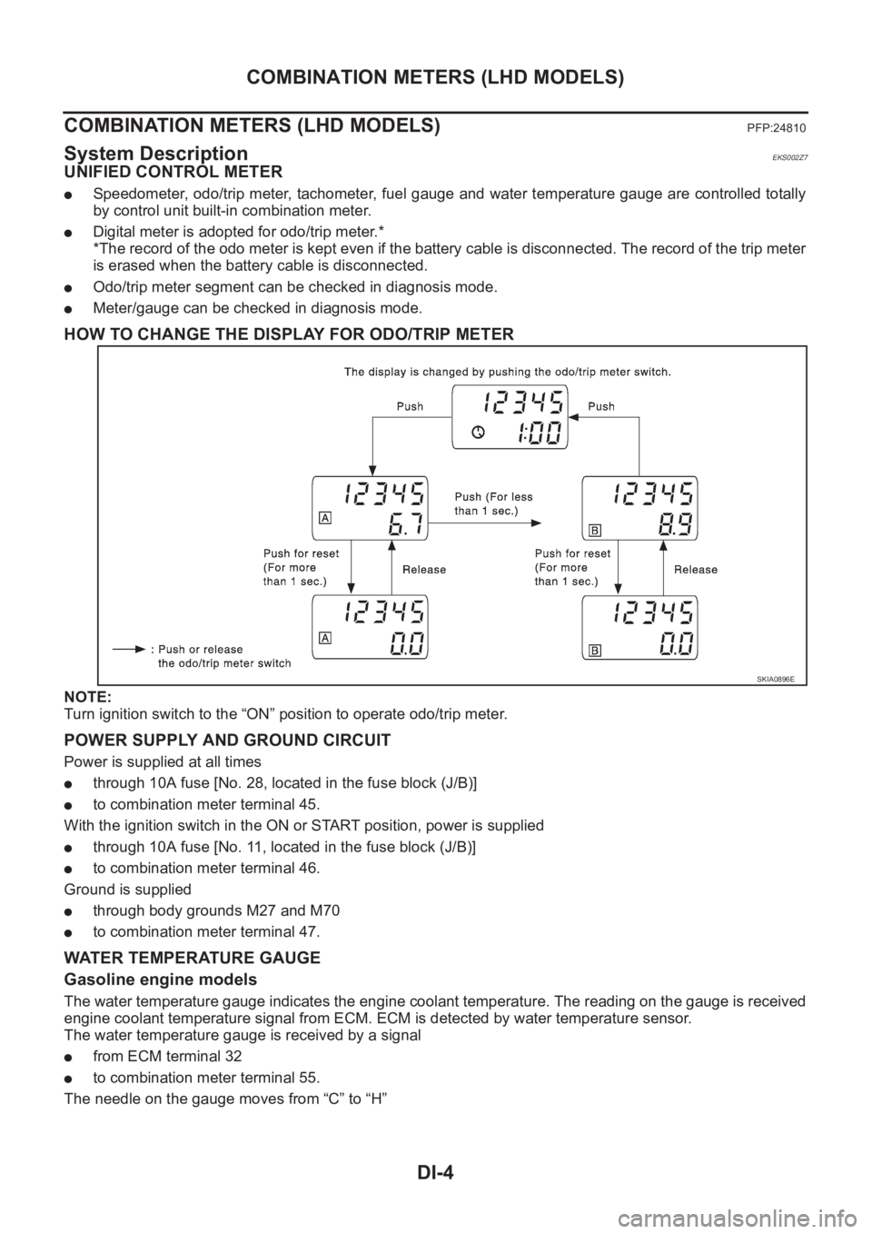
HOW TO CHANGE THE DISPLAY FOR ODO/TRIP METER
NOTE:
Turn ignition switch to the “ON” position to operate odo/trip meter.
POWER SUPPLY AND GROUND CIRCUIT
Power is supplied at all times
●through 10A fuse [No. 28, located in the fuse block (J/B)]
●to combination meter terminal 45.
With the ignition switch in the ON or START position, power is supplied
●through 10A fuse [No. 11, located in the fuse block (J/B)]
●to combination meter terminal 46.
Ground is supplied
●through body grounds M27 and M70
●to combination meter terminal 47.
WATER TEMPERATURE GAUGE
Gasoline engine models
The water temperature gauge indicates the engine coolant temperature. The reading on the gauge is received
engine coolant temperature signal from ECM. ECM is detected by water temperature sensor.
The water temperature gauge is received by a signal
●from ECM terminal 32
●to combination meter terminal 55.
The needle on the gauge moves from “C” to “H”
SKIA0896E
Page 3563 of 3833
COMBINATION METERS (LHD MODELS)
DI-5
C
D
E
F
G
H
I
J
L
MA
B
DI
Diesel engine models
The water temperature gauge indicates the engine coolant temperature. The reading on the gauge is based
on the resistance of the thermal transmitter.
As the temperature of the coolant increases, the resistance of the thermal transmitter decreases. A variable
ground is supplied to terminal 55 of the combination meter for the water temperature gauge. The needle on
the gauge moves from “C” to “H”.
TACHOMETER
The tachometer indicates engine speed in revolutions per minute (rpm).
The tachometer is regulated by a signal
●from terminal 36 (Gasoline engine models) or D1 (Diesel engine models) of the ECM
●to combination meter terminal 54 for the tachometer.
FUEL GAUGE
The fuel gauge indicates the approximate fuel level in the fuel tank.
The fuel gauge is regulated by a variable ground signal supplied
●from body grounds, B8 and B18
●through terminals 4 and 1 of the fuel level sensor unit and
●through terminals 1 and 3 of the Sub fuel level sensor unit
●to combination meter terminal 51 for the fuel gauge.
SPEEDOMETER
The combination meter provides a voltage signal to the vehicle speed signal from 4WD/ABS control unit (with-
out ESP) or 4WD control unit (with ESP).
The voltage is supplied
●from combination meter terminal 52 for the speedometer
●to terminal 20 of 4WD control unit (with ESP) or 4WD/ABS control unit (without ESP).
The speedometer converts the voltage into the vehicle speed displayed.
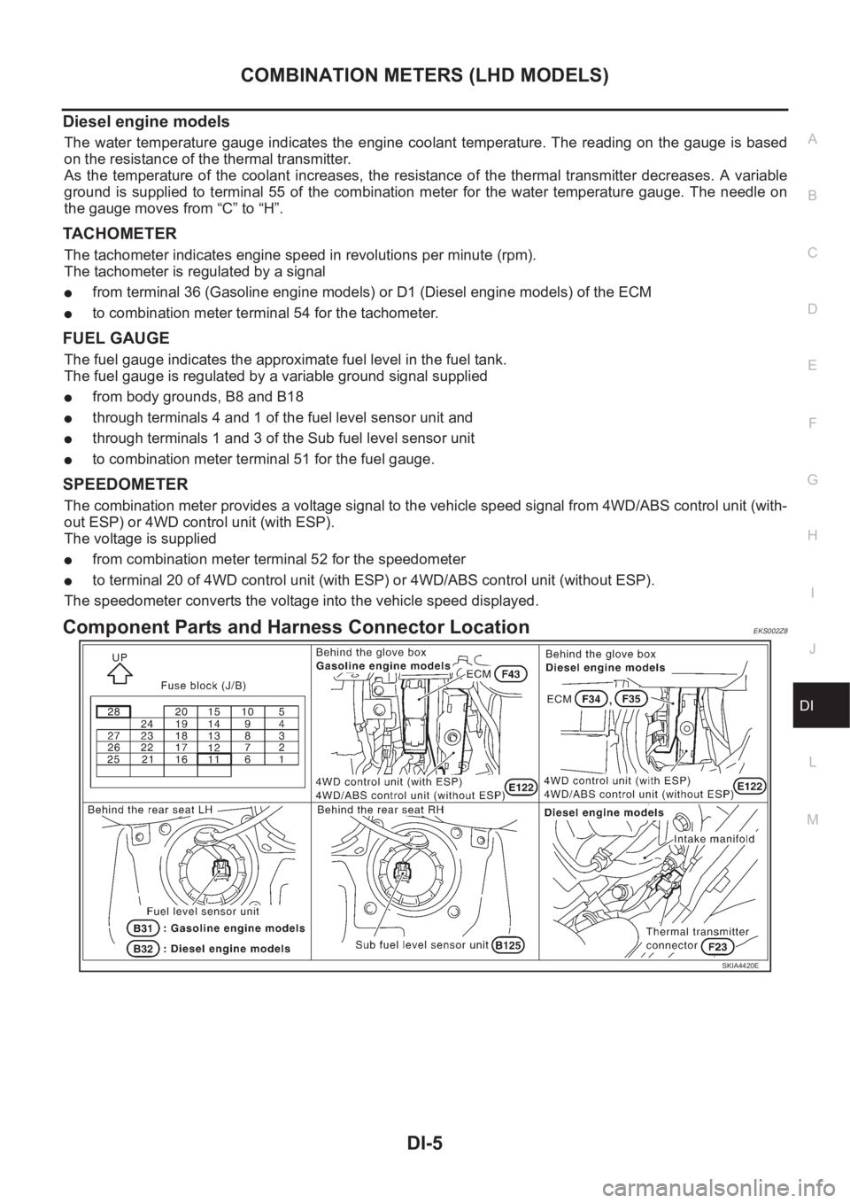
Component Parts and Harness Connector LocationEKS002Z8
SKIA4420E
Page 3582 of 3833
DI-24
COMBINATION METERS (RHD MODELS)
COMBINATION METERS (RHD MODELS)
PFP:24810
System DescriptionEKS0030H
UNIFIED CONTROL METER
●Speedometer, odo/trip meter, tachometer, fuel gauge and water temperature gauge are controlled totally
by control unit built-in combination meter.
●Digital meter is adopted for odo/trip meter.*
*The record of the odo meter is kept even if the battery cable is disconnected. The record of the trip meter
is erased when the battery cable is disconnected.
●Odo/trip meter segment can be checked in diagnosis mode.
●Meter/gauge can be checked in diagnosis mode.
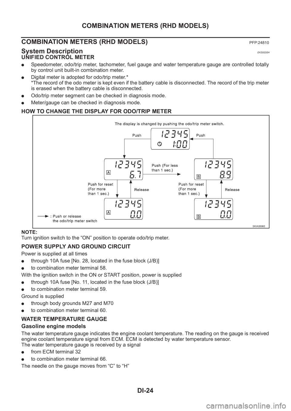
HOW TO CHANGE THE DISPLAY FOR ODO/TRIP METER
NOTE:
Turn ignition switch to the “ON” position to operate odo/trip meter.
POWER SUPPLY AND GROUND CIRCUIT
Power is supplied at all times
●through 10A fuse [No. 28, located in the fuse block (J/B)]
●to combination meter terminal 58.
With the ignition switch in the ON or START position, power is supplied
●through 10A fuse [No. 11, located in the fuse block (J/B)]
●to combination meter terminal 59.
Ground is supplied
●through body grounds M27 and M70
●to combination meter terminal 60.
WATER TEMPERATURE GAUGE
Gasoline engine models
The water temperature gauge indicates the engine coolant temperature. The reading on the gauge is received
engine coolant temperature signal from ECM. ECM is detected by water temperature sensor.
The water temperature gauge is received by a signal
●from ECM terminal 32
●to combination meter terminal 66.
The needle on the gauge moves from “C” to “H”
SKIA0896E
Page 3583 of 3833
COMBINATION METERS (RHD MODELS)
DI-25
C
D
E
F
G
H
I
J
L
MA
B
DI
Diesel engine models
The water temperature gauge indicates the engine coolant temperature. The reading on the gauge is based
on the resistance of the thermal transmitter.
As the temperature of the coolant increases, the resistance of the thermal transmitter decreases. A variable
ground is supplied to terminal 66 of the combination meter for the water temperature gauge. The needle on
the gauge moves from “C” to “H”.
TACHOMETER
The tachometer indicates engine speed in revolutions per minute (rpm).
The tachometer is regulated by a signal
●from terminal 36 (Gasoline engine models) or D1 (Diesel engine models) of the ECM
●to combination meter terminal 41 for the tachometer.
FUEL GAUGE
The fuel gauge indicates the approximate fuel level in the fuel tank.
The fuel gauge is regulated by a variable ground signal supplied
●from body grounds, B107 and B119
●through terminals 4 and 1 of the fuel level sensor unit and
●through terminals 1 and 3 of the sub fuel level sensor unit
●to combination meter terminal 40 for the fuel gauge.
SPEEDOMETER
The combination meter provides a voltage signal to the vehicle speed signal from 4WD/ABS control unit (with-
out ESP) or 4WD control unit (with ESP).
The voltage is supplied
●from combination meter terminal 42 for the speedometer
●to terminal 20 of 4WD control unit (with ESP) or 4WD/ABS control unit (without ESP).
The speedometer converts the voltage into the vehicle speed displayed.
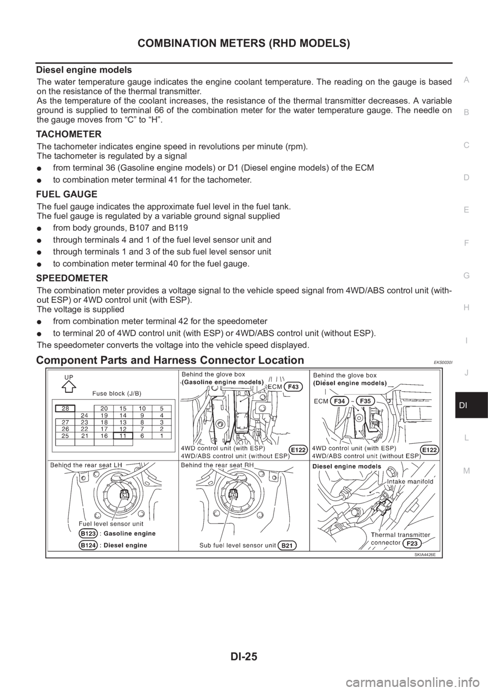
Component Parts and Harness Connector LocationEKS0030I
SKIA4426E