2001 NISSAN X-TRAIL ignition
[x] Cancel search: ignitionPage 3033 of 3833
DRIVER AIR BAG MODULE
SRS-31
C
D
E
F
G
I
J
K
L
MA
B
SRS
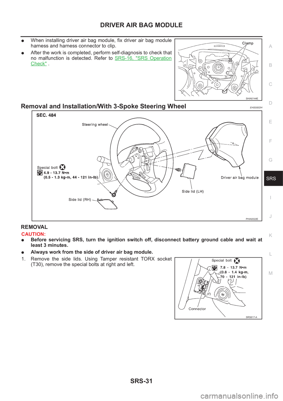
●When installing driver air bag module, fix driver air bag module
harness and harness connector to clip.
●After the work is completed, perform self-diagnosis to check that
no malfunction is detected. Refer to SRS-16, "
SRS Operation
Check" .
Removal and Installation/With 3-Spoke Steering WheelEHS000DH
REMOVAL
CAUTION:
●Before servicing SRS, turn the ignition switch off, disconnect battery ground cable and wait at
least 3 minutes.
●Always work from the side of driver air bag module.
1. Remove the side lids. Using Tamper resistant TORX socket
(T30), remove the special bolts at right and left.
SHIA0144E
PHIA0022E
SRS617-A
Page 3035 of 3833
SPIRAL CABLE
SRS-33
C
D
E
F
G
I
J
K
L
MA
B
SRS
SPIRAL CABLEPFP:25554
Removal and InstallationEHS000D8
REMOVAL
CAUTION:
●Before servicing SRS, turn the ignition switch off, disconnect both battery cables and wait at least
3 minutes.
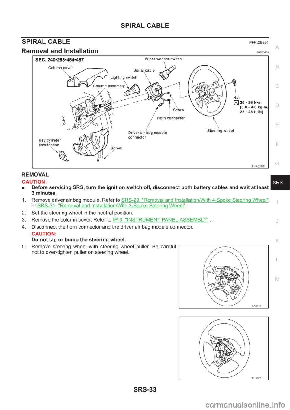
1. Remove driver air bag module. Refer to SRS-29, "
Removal and Installation/With 4-Spoke Steering Wheel"
or SRS-31, "Removal and Installation/With 3-Spoke Steering Wheel" .
2. Set the steering wheel in the neutral position.
3. Remove the column cover. Refer to IP-3, "
INSTRUMENT PANEL ASSEMBLY" .
4. Disconnect the horn connector and the driver air bag module connector.
CAUTION:
Do not tap or bump the steering wheel.
5. Remove steering wheel with steering wheel puller. Be careful
not to over-tighten puller on steering wheel.
PHIA0024E
SRS676
SRS823
Page 3037 of 3833
FRONT PASSENGER AIR BAG MODULE
SRS-35
C
D
E
F
G
I
J
K
L
MA
B
SRS
FRONT PASSENGER AIR BAG MODULEPFP:K8515
Removal and InstallationEHS000D9
REMOVAL
CAUTION:
●Before servicing SRS, turn the ignition switch off, disconnect both battery cables and wait at least
3 minutes.
●Always work from the side of or under front passenger air bag module.
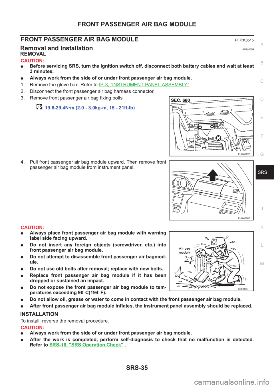
1. Remove the glove box. Refer to IP-3, "
INSTRUMENT PANEL ASSEMBLY" .
2. Disconnect the front passenger air bag harness connector.
3. Remove front passenger air bag fixing bolts
4. Pull front passenger air bag module upward. Then remove front
passenger air bag module from instrument panel.
CAUTION:
●Always place front passenger air bag module with warning
label side facing upward.
●Do not insert any foreign objects (screwdriver, etc.) into
front passenger air bag module.
●Do not attempt to disassemble front passenger air bagmod-
ule.
●Do not use old bolts after removal; replace with new bolts.
●Replace front passenger air bag module if it has been
dropped or sustained an impact.
●Do not expose the front passenger air bag module to tem-
peratures exceeding 90°C(194°F).
●Do not allow oil, grease or water to come in contact with the front passenger air bag module.
●After front passenger air bag module inflates, the instrument panel assembly should be replaced.
INSTALLATION
To install, reverse the removal procedure.
CAUTION:
●Always work from the side of or under front passenger air bag module.
●After the work is completed, perform self-diagnosis to check that no malfunction is detected.
Refer to SRS-16, "
SRS Operation Check" . : 19.6-29.4N·m (2.0 - 3.0kg-m, 15 - 21ft-lb)
PHIA0027E
PHIA0026E
SBF814E
Page 3038 of 3833
SRS-36
FRONT SIDE AIR BAG MODULE
FRONT SIDE AIR BAG MODULE
PFP:K8EH0
Removal and InstallationEHS000DA
REMOVAL
CAUTION:
●Before servicing SRS, turn the ignition switch off, disconnect both battery cables and wait at least
3 minutes.
●Always work from the rear of the front side air bag module.
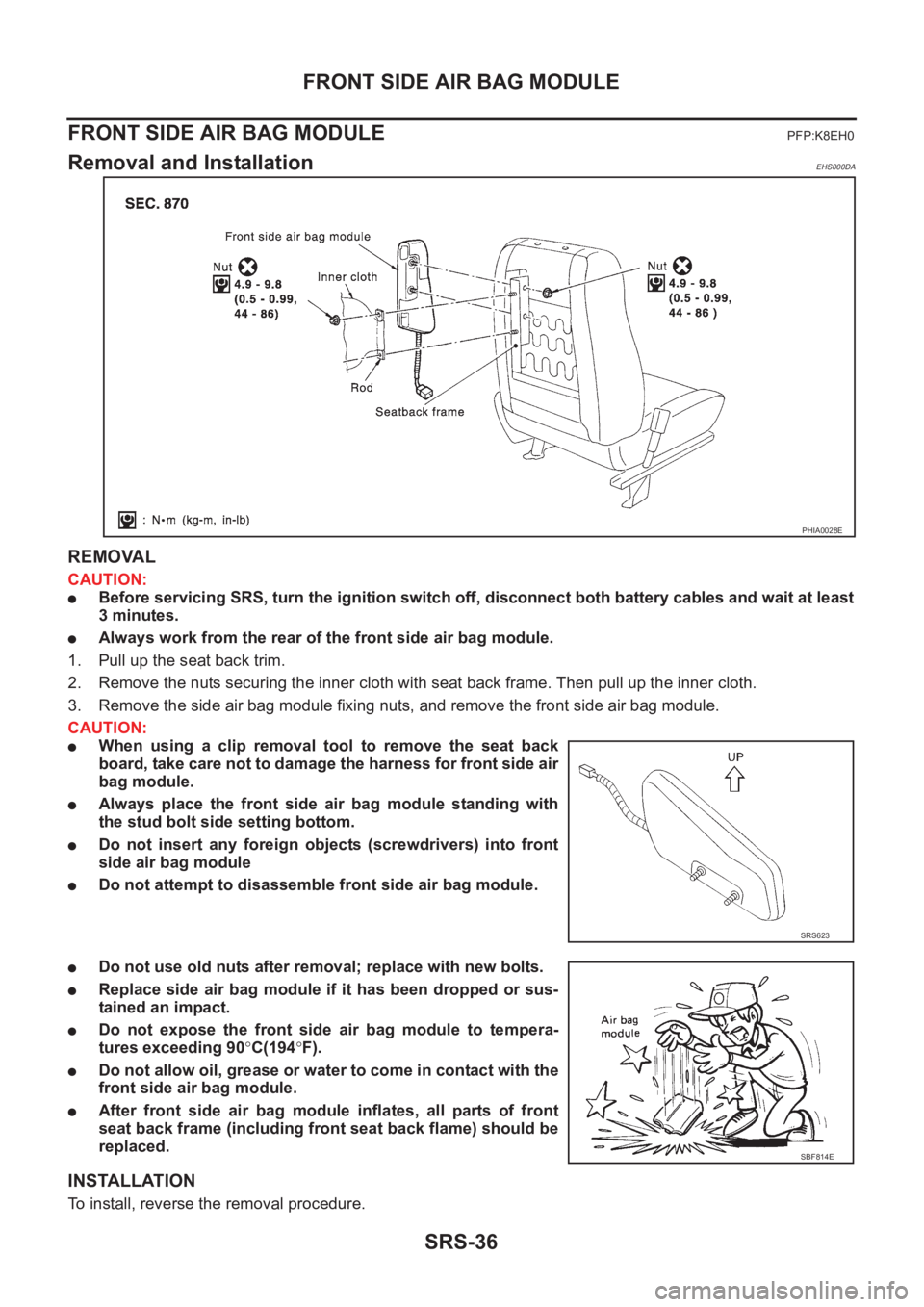
1. Pull up the seat back trim.
2. Remove the nuts securing the inner cloth with seat back frame. Then pull up the inner cloth.
3. Remove the side air bag module fixing nuts, and remove the front side air bag module.
CAUTION:
●When using a clip removal tool to remove the seat back
board, take care not to damage the harness for front side air
bag module.
●Always place the front side air bag module standing with
the stud bolt side setting bottom.
●Do not insert any foreign objects (screwdrivers) into front
side air bag module
●Do not attempt to disassemble front side air bag module.
●Do not use old nuts after removal; replace with new bolts.
●Replace side air bag module if it has been dropped or sus-
tained an impact.
●Do not expose the front side air bag module to tempera-
tures exceeding 90°C(194°F).
●Do not allow oil, grease or water to come in contact with the
front side air bag module.
●After front side air bag module inflates, all parts of front
seat back frame (including front seat back flame) should be
replaced.
INSTALLATION
To install, reverse the removal procedure.
PHIA0028E
SRS623
SBF814E
Page 3040 of 3833
SRS-38
SIDE AIR BAG (SATELLITE) SENSOR
SIDE AIR BAG (SATELLITE) SENSOR
PFP:98830
Removal and InstallationEHS000DB
REMOVAL
CAUTION:
●Before servicing SRS, turn the ignition switch off, disconnect both battery cables and wait at least
3 minutes.
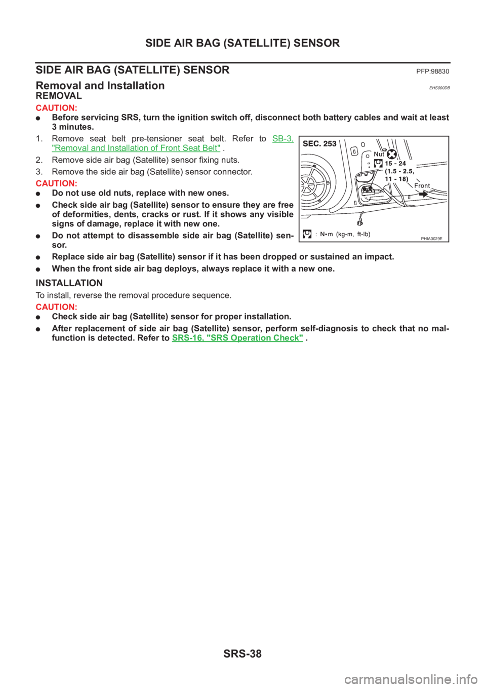
1. Remove seat belt pre-tensioner seat belt. Refer to SB-3,
"Removal and Installation of Front Seat Belt" .
2. Remove side air bag (Satellite) sensor fixing nuts.
3. Remove the side air bag (Satellite) sensor connector.
CAUTION:
●Do not use old nuts, replace with new ones.
●Check side air bag (Satellite) sensor to ensure they are free
of deformities, dents, cracks or rust. If it shows any visible
signs of damage, replace it with new one.
●Do not attempt to disassemble side air bag (Satellite) sen-
sor.
●Replace side air bag (Satellite) sensor if it has been dropped or sustained an impact.
●When the front side air bag deploys, always replace it with a new one.
INSTALLATION
To install, reverse the removal procedure sequence.
CAUTION:
●Check side air bag (Satellite) sensor for proper installation.
●After replacement of side air bag (Satellite) sensor, perform self-diagnosis to check that no mal-
function is detected. Refer to SRS-16, "
SRS Operation Check" .
PHIA0029E
Page 3042 of 3833
SRS-40
DIAGNOSIS SENSOR UNIT
DIAGNOSIS SENSOR UNIT
PFP:28556
Removal and InstallationEHS000DD
REMOVAL
CAUTION:
●Before servicing SRS, turn the ignition switch off, disconnect both battery cables and wait at least
3 minutes.
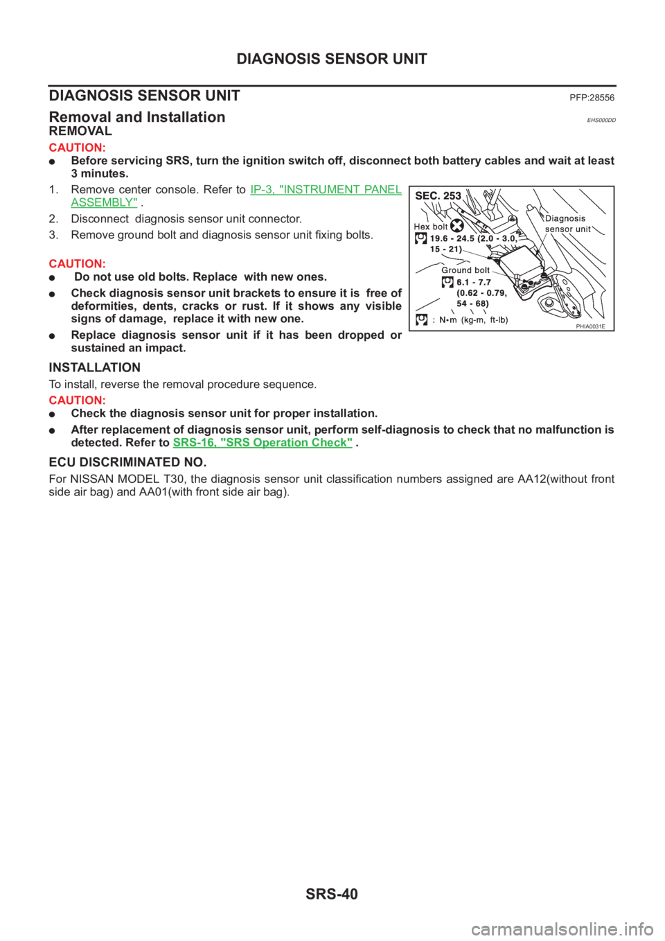
1. Remove center console. Refer to IP-3, "
INSTRUMENT PANEL
ASSEMBLY" .
2. Disconnect diagnosis sensor unit connector.
3. Remove ground bolt and diagnosis sensor unit fixing bolts.
CAUTION:
● Do not use old bolts. Replace with new ones.
●Check diagnosis sensor unit brackets to ensure it is free of
deformities, dents, cracks or rust. If it shows any visible
signs of damage, replace it with new one.
●Replace diagnosis sensor unit if it has been dropped or
sustained an impact.
INSTALLATION
To install, reverse the removal procedure sequence.
CAUTION:
●Check the diagnosis sensor unit for proper installation.
●After replacement of diagnosis sensor unit, perform self-diagnosis to check that no malfunction is
detected. Refer to SRS-16, "
SRS Operation Check" .
ECU DISCRIMINATED NO.
For NISSAN MODEL T30, the diagnosis sensor unit classification numbers assigned are AA12(without front
side air bag) and AA01(with front side air bag).
PHIA0031E
Page 3053 of 3833

BL-1
BODY, LOCK & SECURITY SYSTEM
I BODY
CONTENTS
C
D
E
F
G
H
J
K
L
M
SECTION
A
B
BL
BODY, LOCK & SECURITY SYSTEM
PRECAUTIONS .......................................................... 3
Precautions for Supplemental Restraint System
(SRS) “AIR BAG” and “SEAT BELT PRE-TEN-
SIONER” .................................................................. 3
Precautions .............................................................. 3
HOOD ......................................................................... 4
Fitting Adjustment .................................................... 4
FRONT END HEIGHT ADJUSTMENT AND LAT-
ERAL/LONGITUDINAL CLEARANCE ADJUST-
MENT .................................................................... 4
SURFACE HEIGHT ADJUSTMENT ..................... 4
Removal and Installation of Hood Assembly ............ 5
Removal and Installation of Hood Lock Control ....... 6
REMOVAL ............................................................. 6
INSTALLATION ..................................................... 7
Hood Lock Control Inspection .................................. 7
DOOR ......................................................................... 8
Fitting Adjustment .................................................... 8
FRONT DOOR ...................................................... 8
REAR DOOR ........................................................ 8
STRIKER ADJUSTMENT ..................................... 8
Removal and Installation .......................................... 9
Door Weatherstrip .................................................. 10
POWER DOOR LOCK SYSTEM ...............................11
System Description ................................................. 11
OPERATION ........................................................ 11
Component Parts and Harness Connector Location .... 11
Schematic .............................................................. 12
Wiring Diagram — D/LOCK — ............................... 13
Terminal and Reference Value for Time Control Unit ... 17
Symptom Chart ...................................................... 18
Power Supply and Ground Circuit Check ............... 18
Door Lock/Unlock Switch Check ............................ 19
Door Key Cylinder Switch Check ........................... 20
Front Door Lock Actuator (Driver Side) Check ....... 21
Front Door Lock Actuator (Passenger Side) Check ... 22
Rear Door Lock Actuator LH Check ....................... 23
Rear Door Lock Actuator RH Check ...................... 24
Back Door Lock Actuator Check ............................ 25
Door Switch Check ................................................. 26Door Unlock Sensor Check .................................... 26
Key Switch Check ................................................... 27
POWER DOOR LOCK — SUPER LOCK — ............ 29
System Description ................................................. 29
OUTLINE ............................................................. 29
OPERATION .....................................................
... 29
Schematic ............................................................... 31
Wiring Diagram — S/LOCK — ............................... 32
Terminal and Reference Value for Time Control Unit ... 38
Trouble Diagnoses ................................................. 39
PRELIMINARY CHECK ....................................... 39
SYMPTOM CHART ............................................. 40
Power Supply and Ground Circuit Check ............... 41
Door Lock/Unlock Switch Check ............................ 42
Door Key Cylinder Switch Check ............................ 43
Front Door Lock Actuator (Driver Side) Check ....... 44
Front Door Lock Actuator (Passenger Side) Check ... 45
Rear Door Lock Actuator LH Check ....................... 46
Rear Door Lock Actuator RH Check ....................... 47
Back Door Lock Actuator Check ............................. 48
Door Switch Check ................................................. 49
Door Unlock Sensor Check .................................... 50
Key Switch Check ................................................... 51
Super Lock Actuator Check .................................... 52
NATS Release Signal Check .................................. 53
Ignition Switch “ON” Circuit Check ......................... 54
MULTI-REMOTE CONTROL SYSTEM ..................... 55
Component Parts and Harness Connector Location ... 55
System Description ................................................. 56
FUNCTION .......................................................... 56
LOCK OPERATION ............................................. 56
UNLOCK OPERATION ........................................ 56
HAZARD REMINDER ......................................... 56
MULTI-REMOTE CONTROLLER ID CODE
ENTRY ................................................................ 56
Wiring Diagram — MULTI — .................................. 57
Terminal and Reference Value for Multi-remote
Control Unit ............................................................. 59
Symptom Chart ....................................................... 59
Remote Controller Battery Check ........................... 59
Page 3063 of 3833
POWER DOOR LOCK SYSTEM
BL-11
C
D
E
F
G
H
J
K
L
MA
B
BL
POWER DOOR LOCK SYSTEMPFP:24814
System DescriptionEIS001SE
OPERATION
Power door lock/unlock operation by door key cylinder
●With the key inserted into driver's door key cylinder, turning it to LOCK will lock all doors.
●With the key inserted into driver's door key cylinder, turning it to UNLOCK will unlock all doors.
Power door lock/unlock operation by lock/unlock switch
●With lock/unlock switch setting to LOCK will lock all doors.
●With lock/unlock switch setting to UNLOCK will unlock all doors.
Key reminder system
●If the ignition key is in the ignition key cylinder and driver door is open, setting lock/unlock switch, lock
knob, key or multi-remote controller to “LOCK” locks the door once but then immediately unlocks all doors.
(signal from door unlock sensor driver side)
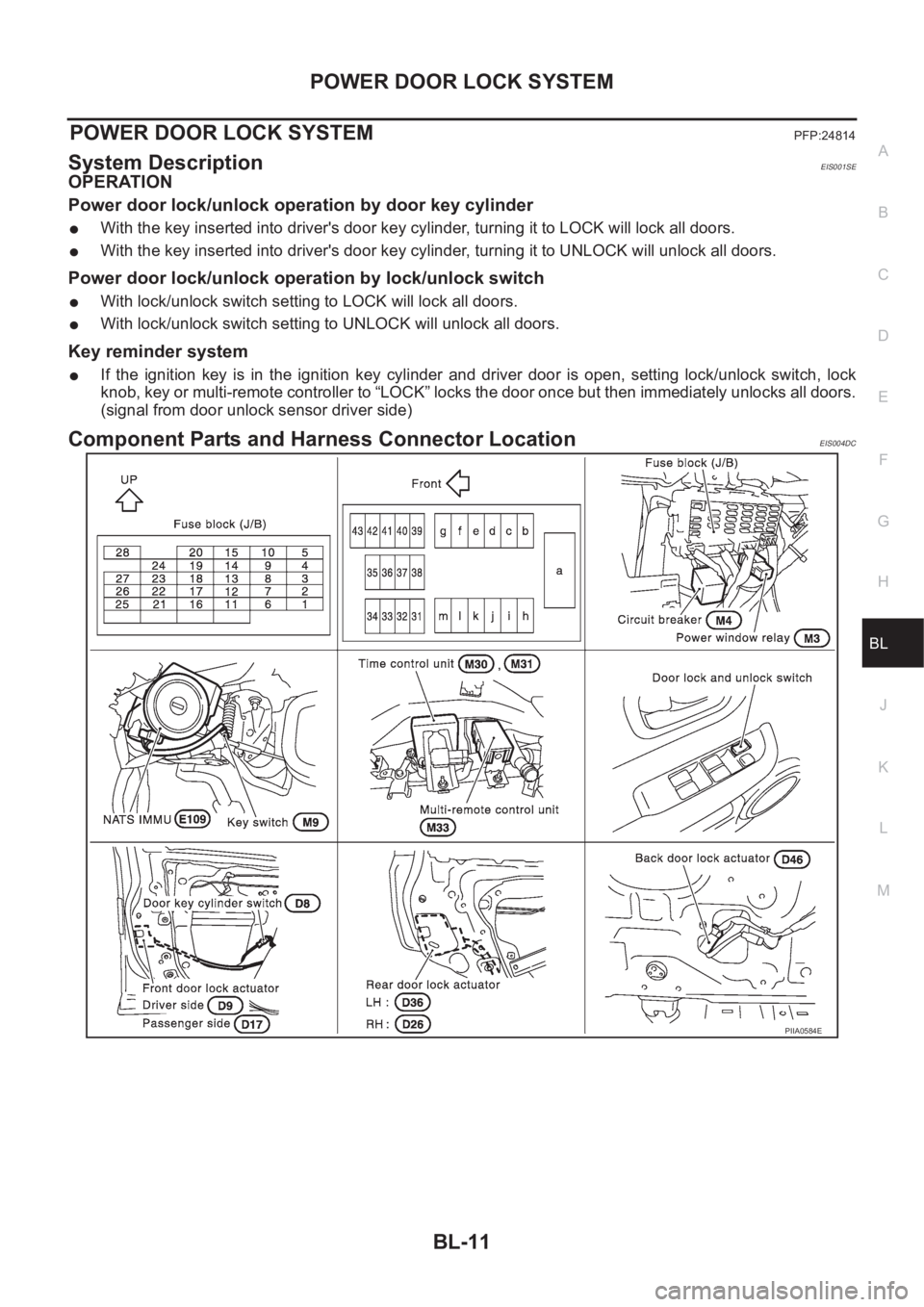
Component Parts and Harness Connector LocationEIS004DC
PIIA0584E