Page 3106 of 3833
BL-54
POWER DOOR LOCK — SUPER LOCK —
Ignition Switch “ON” Circuit Check
EIS001SP
1. CHECK IGNITION ON SIGNAL
1. Disconnect time control unit connector.
2. Check voltage between time control unit terminal 17 and ground.
OK or NG
OK >> Ignition ON signal is OK.
NG >> Check the following.
●10A fuse [No. 5, located in fuse block (J/B)]
●Harness for open or short between time control unit and fuse Terminal Ignition switch position
+ – OFF ACC ON
17 Ground 0V 0VBattery
voltage
SIIA1226E
Page 3108 of 3833
BL-56
MULTI-REMOTE CONTROL SYSTEM
System Description
EIS001RE
FUNCTION
Multi-remote control system has the following function.
●Door lock (and set super lock)
●Door unlock (and release super lock)
●Hazard reminder
LOCK OPERATION
To lock door by multi-remote controller, the ignition switch must be at OFF.
When the LOCK signal is input to multi-remote control unit (the antenna of the system is combined with multi-
remote control unit), ground is supplied
●through multi-remote control unit terminal 5
●to time control unit terminal 32.
Then time control unit operates to lock doors and set super lock (models with super lock).
UNLOCK OPERATION
When the UNLOCK signal is input to multi-remote control unit (the antenna of the system is combined with
multi-remote control unit), ground is supplied
●through multi-remote control unit terminal 6
●to time control unit terminal 33.
Time control unit operates to unlock driver's door and release super lock (models with super lock).
Then, if an unlock signal is sent from the remote controller again within 5 seconds, all other doors will be
unlocked.
HAZARD REMINDER
When the doors are locked or unlocked by multi-remote controller (signal from driver side unlock sensor), sup-
ply power to hazard warning lamp flashes as follows
●Lock operation: Flash once
●Unlock operation: Flash twice
MULTI-REMOTE CONTROLLER ID CODE ENTRY
A maximum of four remote controllers can be entered.
To enter ID code entry, the following signals must be input to the multi-remote control unit.
●Ignition switch (ON)
●Signal from remote controller
For detailed procedure, refer to BL-63, "
ID Code Entry Procedure" .
Page 3112 of 3833
BL-60
MULTI-REMOTE CONTROL SYSTEM
Power Supply and Ground Circuit Check
EIS001T4
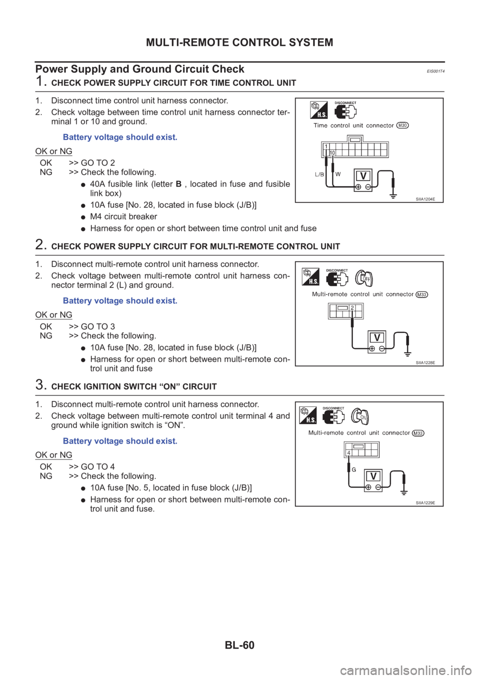
1. CHECK POWER SUPPLY CIRCUIT FOR TIME CONTROL UNIT
1. Disconnect time control unit harness connector.
2. Check voltage between time control unit harness connector ter-
minal 1 or 10 and ground.
OK or NG
OK >> GO TO 2
NG >> Check the following.
●40A fusible link (letter B , located in fuse and fusible
link box)
●10A fuse [No. 28, located in fuse block (J/B)]
●M4 circuit breaker
●Harness for open or short between time control unit and fuse
2. CHECK POWER SUPPLY CIRCUIT FOR MULTI-REMOTE CONTROL UNIT
1. Disconnect multi-remote control unit harness connector.
2. Check voltage between multi-remote control unit harness con-
nector terminal 2 (L) and ground.
OK or NG
OK >> GO TO 3
NG >> Check the following.
●10A fuse [No. 28, located in fuse block (J/B)]
●Harness for open or short between multi-remote con-
trol unit and fuse
3. CHECK IGNITION SWITCH “ON” CIRCUIT
1. Disconnect multi-remote control unit harness connector.
2. Check voltage between multi-remote control unit terminal 4 and
ground while ignition switch is “ON”.
OK or NG
OK >> GO TO 4
NG >> Check the following.
●10A fuse [No. 5, located in fuse block (J/B)]
●Harness for open or short between multi-remote con-
trol unit and fuse. Battery voltage should exist.
SIIA1204E
Battery voltage should exist.
SIIA1228E
Battery voltage should exist.
SIIA1229E
Page 3113 of 3833
MULTI-REMOTE CONTROL SYSTEM
BL-61
C
D
E
F
G
H
J
K
L
MA
B
BL
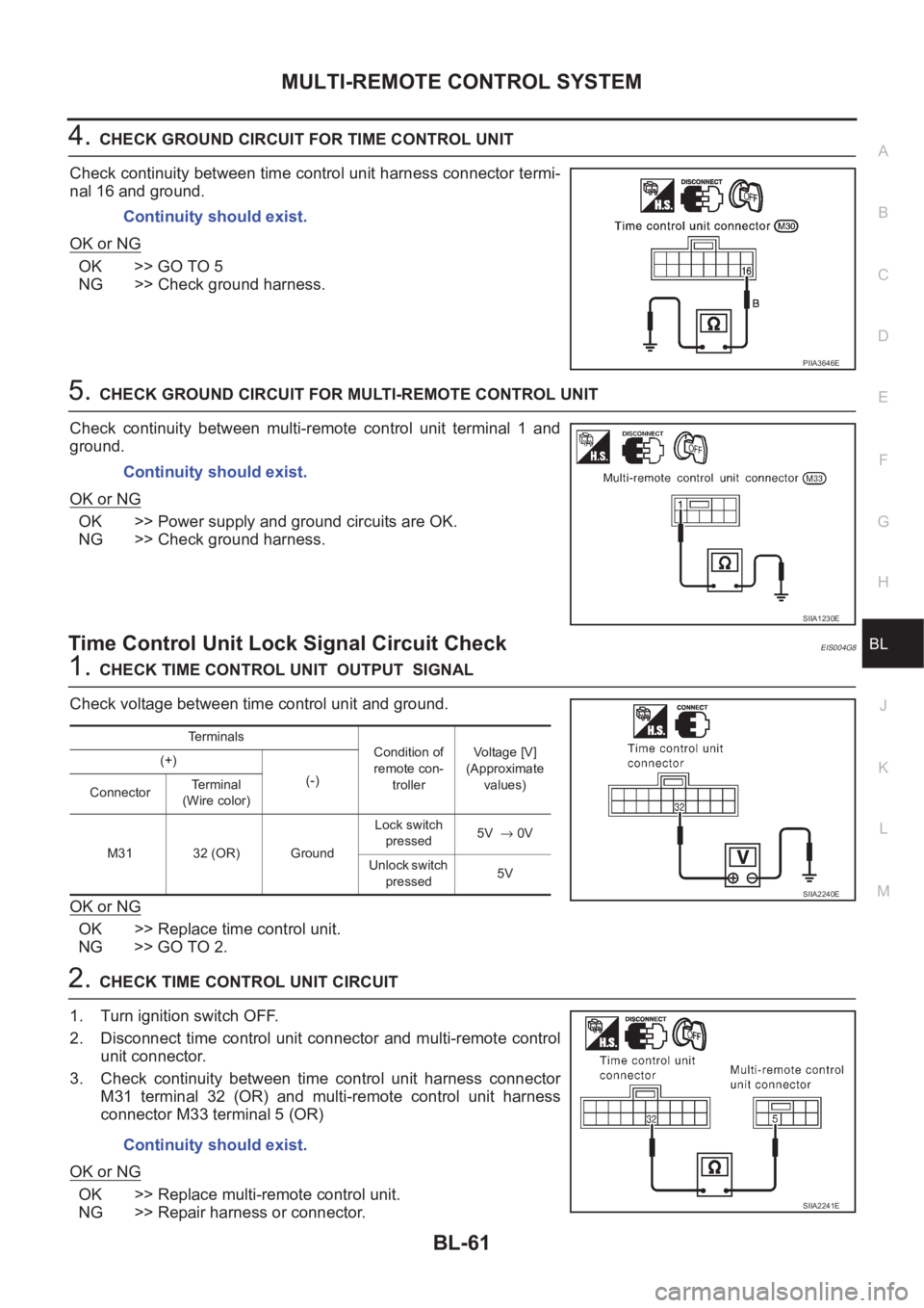
4.CHECK GROUND CIRCUIT FOR TIME CONTROL UNIT
Check continuity between time control unit harness connector termi-
nal 16 and ground.
OK or NG
OK >> GO TO 5
NG >> Check ground harness.
5.CHECK GROUND CIRCUIT FOR MULTI-REMOTE CONTROL UNIT
Check continuity between multi-remote control unit terminal 1 and
ground.
OK or NG
OK >> Power supply and ground circuits are OK.
NG >> Check ground harness.
Time Control Unit Lock Signal Circuit CheckEIS004G8
1.CHECK TIME CONTROL UNIT OUTPUT SIGNAL
Check voltage between time control unit and ground.
OK or NG
OK >> Replace time control unit.
NG >> GO TO 2.
2.CHECK TIME CONTROL UNIT CIRCUIT
1. Turn ignition switch OFF.
2. Disconnect time control unit connector and multi-remote control
unit connector.
3. Check continuity between time control unit harness connector
M31 terminal 32 (OR) and multi-remote control unit harness
connector M33 terminal 5 (OR)
OK or NG
OK >> Replace multi-remote control unit.
NG >> Repair harness or connector.Continuity should exist.
PIIA3646E
Continuity should exist.
SIIA1230E
Terminals
Condition of
remote con-
trollerVoltage [V]
(Approximate
values) (+)
(-)
ConnectorTerminal
(Wire color)
M31 32 (OR) GroundLock switch
pressed5V → 0V
Unlock switch
pressed5V
SIIA2240E
Continuity should exist.
SIIA2241E
Page 3114 of 3833
BL-62
MULTI-REMOTE CONTROL SYSTEM
Time Control Unit Unlock Signal Circuit Check
EIS004G9
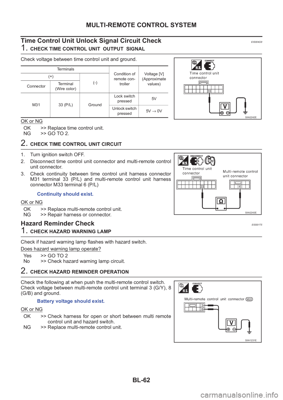
1. CHECK TIME CONTROL UNIT OUTPUT SIGNAL
Check voltage between time control unit and ground.
OK or NG
OK >> Replace time control unit.
NG >> GO TO 2.
2. CHECK TIME CONTROL UNIT CIRCUIT
1. Turn ignition switch OFF.
2. Disconnect time control unit connector and multi-remote control
unit connector.
3. Check continuity between time control unit harness connector
M31 terminal 33 (P/L) and multi-remote control unit harness
connector M33 terminal 6 (P/L)
OK or NG
OK >> Replace multi-remote control unit.
NG >> Repair harness or connector.
Hazard Reminder CheckEIS001T5
1. CHECK HAZARD WARNING LAMP
Check if hazard warning lamp flashes with hazard switch.
Does hazard warning lamp operate?
Yes >> GO TO 2
No >> Check hazard warning lamp circuit.
2. CHECK HAZARD REMINDER OPERATION
Check the following at when push the multi-remote control switch.
Check voltage between multi-remote control unit terminal 3 (G/Y), 8
(G/B) and ground.
OK or NG
OK >> Check harness for open or short between multi remote
control unit and hazard switch.
NG >> Replace multi-remote control unit.
Terminals
Condition of
remote con-
trollerVoltage [V]
(Approximate
values) (+)
(-)
ConnectorTerminal
(Wire color)
M31 33 (P/L) GroundLock switch
pressed5V
Unlock switch
pressed5V → 0V
SIIA2242E
Continuity should exist.
SIIA2243E
Battery voltage should exist.
SIIA1231E
Page 3133 of 3833
NATS (NISSAN ANTI-THEFT SYSTEM)
BL-81
C
D
E
F
G
H
J
K
L
MA
B
BL
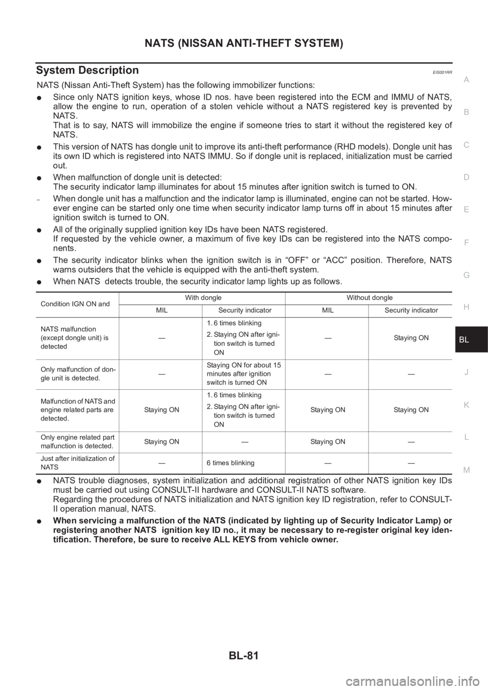
System DescriptionEIS001RR
NATS (Nissan Anti-Theft System) has the following immobilizer functions:
●Since only NATS ignition keys, whose ID nos. have been registered into the ECM and IMMU of NATS,
allow the engine to run, operation of a stolen vehicle without a NATS registered key is prevented by
NATS.
That is to say, NATS will immobilize the engine if someone tries to start it without the registered key of
NATS.
●This version of NATS has dongle unit to improve its anti-theft performance (RHD models). Dongle unit has
its own ID which is registered into NATS IMMU. So if dongle unit is replaced, initialization must be carried
out.
●When malfunction of dongle unit is detected:
The security indicator lamp illuminates for about 15 minutes after ignition switch is turned to ON.
–When dongle unit has a malfunction and the indicator lamp is illuminated, engine can not be started. How-
ever engine can be started only one time when security indicator lamp turns off in about 15 minutes after
ignition switch is turned to ON.
●All of the originally supplied ignition key IDs have been NATS registered.
If requested by the vehicle owner, a maximum of five key IDs can be registered into the NATS compo-
nents.
●The security indicator blinks when the ignition switch is in “OFF” or “ACC” position. Therefore, NATS
warns outsiders that the vehicle is equipped with the anti-theft system.
●When NATS detects trouble, the security indicator lamp lights up as follows.
●NATS trouble diagnoses, system initialization and additional registration of other NATS ignition key IDs
must be carried out using CONSULT-II hardware and CONSULT-II NATS software.
Regarding the procedures of NATS initialization and NATS ignition key ID registration, refer to CONSULT-
II operation manual, NATS.
●When servicing a malfunction of the NATS (indicated by lighting up of Security Indicator Lamp) or
registering another NATS ignition key ID no., it may be necessary to re-register original key iden-
tification. Therefore, be sure to receive ALL KEYS from vehicle owner.
Condition IGN ON andWith dongle Without dongle
MIL Security indicator MIL Security indicator
NATS malfunction
(except dongle unit) is
detected—1. 6 times blinking
2. Staying ON after igni-
tion switch is turned
ON— Staying ON
Only malfunction of don-
gle unit is detected.—Staying ON for about 15
minutes after ignition
switch is turned ON——
Malfunction of NATS and
engine related parts are
detected.Staying ON1. 6 times blinking
2. Staying ON after igni-
tion switch is turned
ONStaying ON Staying ON
Only engine related part
malfunction is detected.Staying ON — Staying ON —
Just after initialization of
NATS— 6 times blinking — —
Page 3134 of 3833
BL-82
NATS (NISSAN ANTI-THEFT SYSTEM)
System Composition
EIS001RS
The immobilizer function of the NATS consists of the following:
●NATS ignition key
●NATS immobilizer control unit (IMMU) located in the ignition key cylinder
●Engine control module (ECM)
●Dongle unit (RHD models)
●Security indicator
SIIA1246E
Page 3137 of 3833
NATS (NISSAN ANTI-THEFT SYSTEM)
BL-85
C
D
E
F
G
H
J
K
L
MA
B
BL
CONSULT-IIEIS001RW
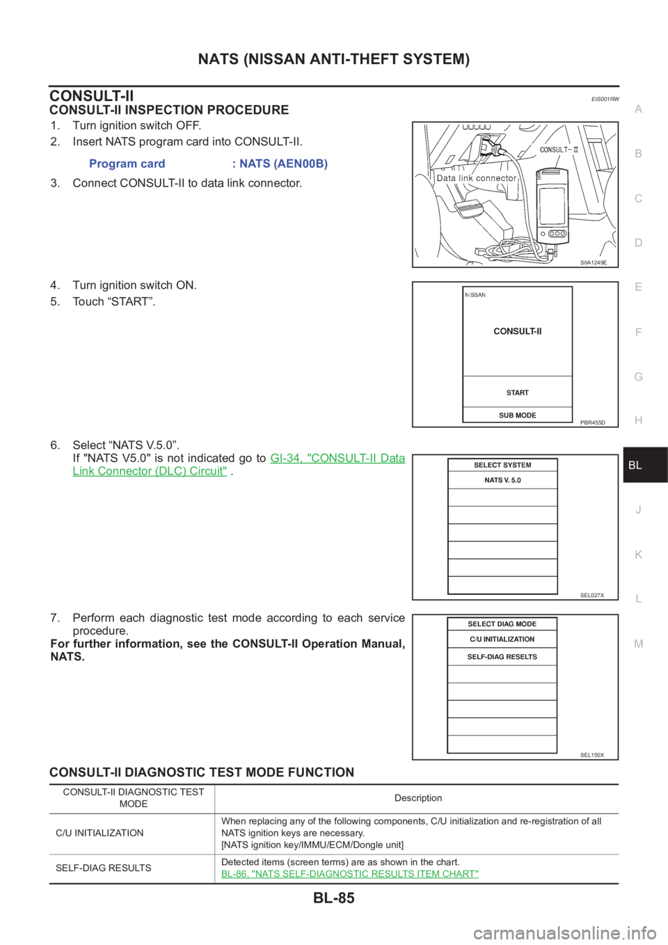
CONSULT-II INSPECTION PROCEDURE
1. Turn ignition switch OFF.
2. Insert NATS program card into CONSULT-II.
3. Connect CONSULT-II to data link connector.
4. Turn ignition switch ON.
5. Touch “START”.
6. Select “NATS V.5.0”.
If "NATS V5.0" is not indicated go to GI-34, "
CONSULT-II Data
Link Connector (DLC) Circuit" .
7. Perform each diagnostic test mode according to each service
procedure.
For further information, see the CONSULT-II Operation Manual,
NATS.
CONSULT-II DIAGNOSTIC TEST MODE FUNCTION
Program card : NATS (AEN00B)
SIIA1249E
PBR455D
SEL027X
SEL150X
CONSULT-II DIAGNOSTIC TEST
MODEDescription
C/U INITIALIZATIONWhen replacing any of the following components, C/U initialization and re-registration of all
NATS ignition keys are necessary.
[NATS ignition key/IMMU/ECM/Dongle unit]
SELF-DIAG RESULTSDetected items (screen terms) are as shown in the chart.
BL-86, "
NATS SELF-DIAGNOSTIC RESULTS ITEM CHART"