Page 3149 of 3833
NATS (NISSAN ANTI-THEFT SYSTEM)
BL-97
C
D
E
F
G
H
J
K
L
MA
B
BL
Diagnostic Procedure 6EIS001TC
“SECURITY INDICATOR LAMP DOES NOT LIGHT UP”
1.CHECK FUSE
Check 10A fuse [No. 28, located in the fuse block (J/B)].
Is 10A fuse OK?
Ye s > > G O T O 2
No >> Replace fuse.
2.CHECK SECURITY INDICATOR LAMP
1. Install 10A fuse.
2. Perform initialization with CONSULT-II.
For initialization, refer to “CONSULT-II Operation Manual NATS”.
3. Turn ignition switch OFF.
4. Start engine and turn ignition switch OFF.
5. Check the security indicator lamp lighting.
Security indicator lamp should be light up.
OK or NG
OK >> INSPECTION END
NG >> GO TO 3
3.CHECK SECURITY INDICATOR LAMP POWER SUPPLY CIRCUIT
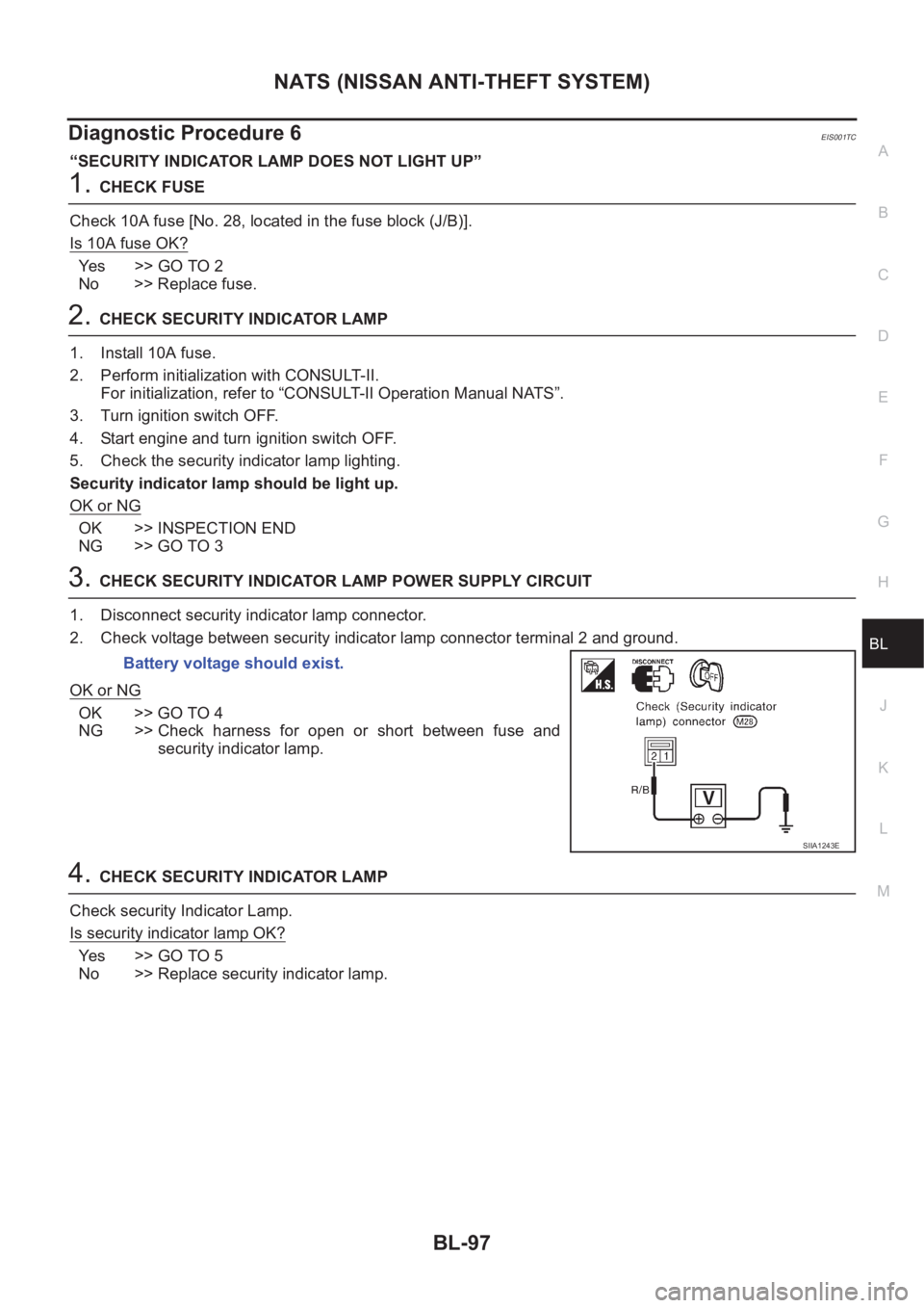
1. Disconnect security indicator lamp connector.
2. Check voltage between security indicator lamp connector terminal 2 and ground.
OK or NG
OK >> GO TO 4
NG >> Check harness for open or short between fuse and
security indicator lamp.
4.CHECK SECURITY INDICATOR LAMP
Check security Indicator Lamp.
Is security indicator lamp OK?
Ye s > > G O T O 5
No >> Replace security indicator lamp.Battery voltage should exist.
SIIA1243E
Page 3150 of 3833
BL-98
NATS (NISSAN ANTI-THEFT SYSTEM)
5. CHECK IMMU FUNCTION
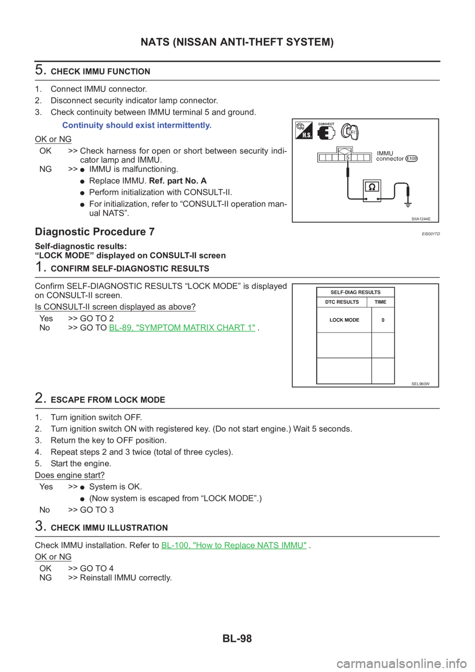
1. Connect IMMU connector.
2. Disconnect security indicator lamp connector.
3. Check continuity between IMMU terminal 5 and ground.
OK or NG
OK >> Check harness for open or short between security indi-
cator lamp and IMMU.
NG >>
●IMMU is malfunctioning.
●Replace IMMU. Ref. part No. A
●Perform initialization with CONSULT-II.
●For initialization, refer to “CONSULT-II operation man-
ual NATS”.
Diagnostic Procedure 7EIS001TD
Self-diagnostic results:
“LOCK MODE” displayed on CONSULT-II screen
1. CONFIRM SELF-DIAGNOSTIC RESULTS
Confirm SELF-DIAGNOSTIC RESULTS “LOCK MODE” is displayed
on CONSULT-II screen.
Is CONSULT-II screen displayed as above?
Yes >> GO TO 2
No >> GO TO BL-89, "
SYMPTOM MATRIX CHART 1" .
2. ESCAPE FROM LOCK MODE
1. Turn ignition switch OFF.
2. Turn ignition switch ON with registered key. (Do not start engine.) Wait 5 seconds.
3. Return the key to OFF position.
4. Repeat steps 2 and 3 twice (total of three cycles).
5. Start the engine.
Does engine start?
Ye s > >●System is OK.
●(Now system is escaped from “LOCK MODE”.)
No >> GO TO 3
3. CHECK IMMU ILLUSTRATION
Check IMMU installation. Refer to BL-100, "
How to Replace NATS IMMU" .
OK or NG
OK >> GO TO 4
NG >> Reinstall IMMU correctly.Continuity should exist intermittently.
SIIA1244E
SEL960W
Page 3162 of 3833
GW-10
REAR WINDOW DEFOGGER
REAR WINDOW DEFOGGER
PFP:25350
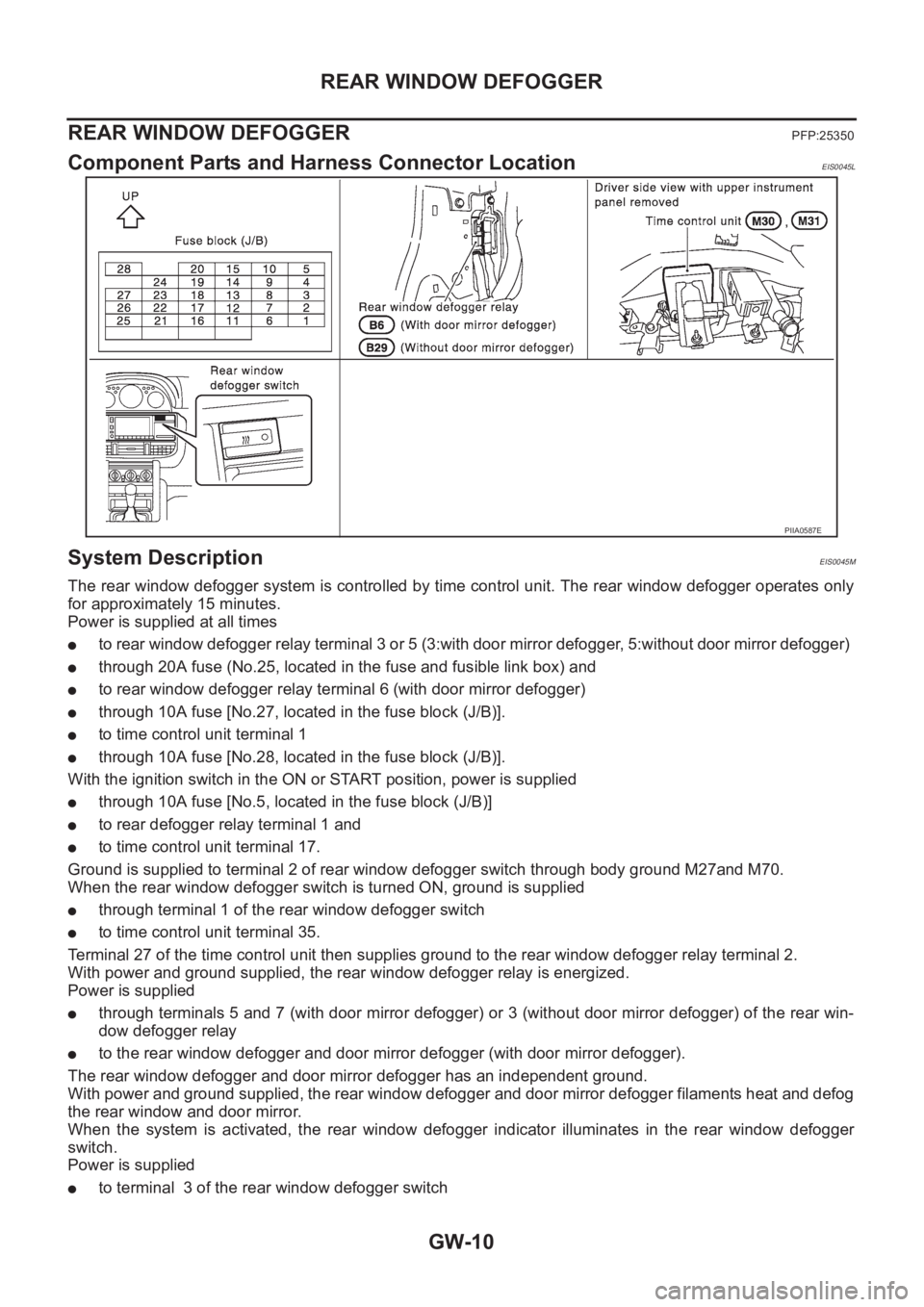
Component Parts and Harness Connector LocationEIS0045L
System DescriptionEIS0045M
The rear window defogger system is controlled by time control unit. The rear window defogger operates only
for approximately 15 minutes.
Power is supplied at all times
●to rear window defogger relay terminal 3 or 5 (3:with door mirror defogger, 5:without door mirror defogger)
●through 20A fuse (No.25, located in the fuse and fusible link box) and
●to rear window defogger relay terminal 6 (with door mirror defogger)
●through 10A fuse [No.27, located in the fuse block (J/B)].
●to time control unit terminal 1
●through 10A fuse [No.28, located in the fuse block (J/B)].
With the ignition switch in the ON or START position, power is supplied
●through 10A fuse [No.5, located in the fuse block (J/B)]
●to rear defogger relay terminal 1 and
●to time control unit terminal 17.
Ground is supplied to terminal 2 of rear window defogger switch through body ground M27and M70.
When the rear window defogger switch is turned ON, ground is supplied
●through terminal 1 of the rear window defogger switch
●to time control unit terminal 35.
Terminal 27 of the time control unit then supplies ground to the rear window defogger relay terminal 2.
With power and ground supplied, the rear window defogger relay is energized.
Power is supplied
●through terminals 5 and 7 (with door mirror defogger) or 3 (without door mirror defogger) of the rear win-
dow defogger relay
●to the rear window defogger and door mirror defogger (with door mirror defogger).
The rear window defogger and door mirror defogger has an independent ground.
With power and ground supplied, the rear window defogger and door mirror defogger filaments heat and defog
the rear window and door mirror.
When the system is activated, the rear window defogger indicator illuminates in the rear window defogger
switch.
Power is supplied
●to terminal 3 of the rear window defogger switch
PIIA0587E
Page 3169 of 3833
REAR WINDOW DEFOGGER
GW-17
C
D
E
F
G
H
J
K
L
MA
B
GW
Terminals and Reference Value for Time Control Unit (RHD models)EIS0046H
Trouble DiagnosesEIS0045T
DIAGNOSTIC PROCEDURE SUBTITLE (SYMPTOM: REAR WINDOW DEFOGGER DOES NOT
ACTIVATE, OR DOES NOT GO OFF AFTER ACTIVATING.)
1.CHECK FUSE INSPECTION
Check the following.
():With door mirror defogger
OK or NG
OK >> GO TO 2
NG >> Replace fuse.
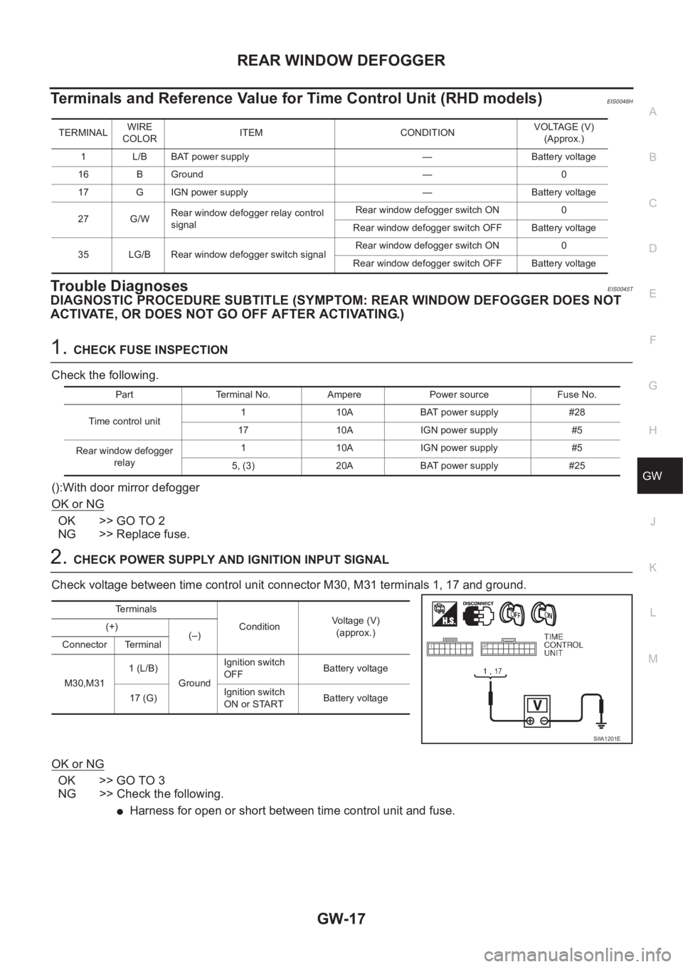
2.CHECK POWER SUPPLY AND IGNITION INPUT SIGNAL
Check voltage between time control unit connector M30, M31 terminals 1, 17 and ground.
OK or NG
OK >> GO TO 3
NG >> Check the following.
●Harness for open or short between time control unit and fuse.
TERMINALWIRE
COLORITEM CONDITIONVOLTAGE (V)
(Approx.)
1 L/B BAT power supply — Battery voltage
16 B Ground — 0
17 G IGN power supply — Battery voltage
27 G/WRear window defogger relay control
signalRear window defogger switch ON 0
Rear window defogger switch OFF Battery voltage
35 LG/B Rear window defogger switch signalRear window defogger switch ON 0
Rear window defogger switch OFF Battery voltage
Part Terminal No. Ampere Power source Fuse No.
Time control unit1 10A BAT power supply #28
17 10A IGN power supply #5
Rear window defogger
relay1 10A IGN power supply #5
5, (3) 20A BAT power supply #25
Terminals
ConditionVoltage (V)
(approx.) (+)
(–)
Connector Terminal
M30,M311 (L/B)
GroundIgnition switch
OFFBattery voltage
17 (G)Ignition switch
ON or STARTBattery voltage
SIIA1201E
Page 3170 of 3833
GW-18
REAR WINDOW DEFOGGER
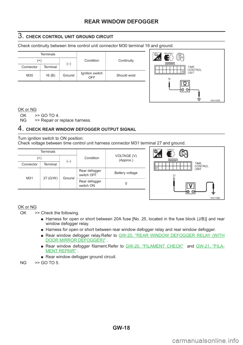
3. CHECK CONTROL UNIT GROUND CIRCUIT
Check continuity between time control unit connector M30 terminal 16 and ground.
OK or NG
OK >> GO TO 4.
NG >> Repair or replace harness.
4. CHECK REAR WINDOW DEFOGGER OUTPUT SIGNAL
Turn ignition switch to ON position.
Check voltage between time control unit harness connector M31 terminal 27 and ground.
OK or NG
OK >> Check the following.
●Harness for open or short between 20A fuse [No. 25, located in the fuse block (J/B)] and rear
window defogger relay.
●Harness for open or short between rear window defogger relay and rear window defogger.
●Rear window defogger relay.Refer to GW-20, "REAR WINDOW DEFOGGER RELAY (WITH
DOOR MIRROR DEFOGGER)" .
●Rear window defogger filament.Refer to GW-20, "FILAMENT CHECK" and GW-21, "FILA-
MENT REPAIR" .
●Rear window defogger ground circuit.
NG >> GO TO 5.
Te r m i n a l s
Condition Continuity (+)
(–)
Connector Terminal
M30 16 (B) GroundIgnition switch
OFFShould exist
SIIA1202E
Te r m i n a l s
ConditionVOLTAGE (V)
(Approx.) (+)
(–)
Connector Terminal
M31 27 (G/W) GroundRear defogger
switch OFFBattery voltage
Rear defogger
switch ON0
SIIA1198E
Page 3171 of 3833
REAR WINDOW DEFOGGER
GW-19
C
D
E
F
G
H
J
K
L
MA
B
GW
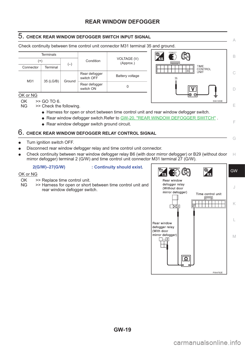
5.CHECK REAR WINDOW DEFOGGER SWITCH INPUT SIGNAL
Check continuity between time control unit connector M31 terminal 35 and ground.
OK or NG
OK >> GO TO 6.
NG >> Check the following.
●Harness for open or short between time control unit and rear window defogger switch.
●Rear window defogger switch.Refer to GW-20, "REAR WINDOW DEFOGGER SWITCH" .
●Rear window defogger switch ground circuit.
6.CHECK REAR WINDOW DEFOGGER RELAY CONTROL SIGNAL
●Turn ignition switch OFF.
●Disconnect rear window defogger relay and time control unit connector.
●Check continuity between rear window defogger relay B6 (with door mirror defogger) or B29 (without door
mirror defogger) terminal 2 (G/W) and time control unit connector M31 terminal 27 (G/W).
OK or NG
OK >> Replace time control unit.
NG >> Harness for open or short between time control unit and
rear window defogger switch.
Terminals
ConditionVOLTAGE (V)
(Approx.) (+)
(–)
Connector Terminal
M31 35 (LG/B) GroundRear defogger
switch OFFBattery voltage
Rear defogger
switch ON0
SIIA1200E
2(G/W)–27(G/W) : Continuity should exist.
PIIA4762E
Page 3175 of 3833

POWER WINDOW SYSTEM
GW-23
C
D
E
F
G
H
J
K
L
MA
B
GW
POWER WINDOW SYSTEMPFP:25401
Component Parts and Harness Connector LocationEIS0045V
System DescriptionEIS0045W
Power is supplied at all times
●from 40A fusible link (letter B , located in the fuse and fusible link box)
●through circuit breaker terminal 1
●through circuit breaker terminal 2
●to power window relay terminal 3 and
●to power window main switch terminal 5 (LHD models) or 3 (RHD models).
With ignition switch in ON or START position, power is supplied
●through 10A fuse [No. 5, located in the fuse block (J/B)]
●to power window relay terminal 1
Ground is supplied to power window relay terminal 2
●through body grounds M27 and M70.
When power and ground are supplied, the power window relay is energized and then power is supplied
●through power window relay terminal 5
●to power window main switch terminal 12,
●to passenger side power window switch terminal 5,
●to rear power window switch LH and RH terminals 5.
PIIA0588E
Page 3177 of 3833
POWER WINDOW SYSTEM
GW-25
C
D
E
F
G
H
J
K
L
MA
B
GW
AUTO OPERATION
The power window AUTO feature enables the driver to open or close the driver's window without holding the
window switch in the down or up position.
The AUTO feature operates on the driver's window.
POWER WINDOW LOCK
The power window lock is designed to lock operation of all windows except for driver's window.
When the lock switch is pressed to lock position, ground of the sub–switches in the power window main switch
is disconnected.This prevents the power window motors from operating.
TIMER FUNCTION
With the timer function, driver power window can be operated for approximately 15 minutes after ignition
switch is turned OFF (positions other than ON). However, the timer will be cancel when a specific signal, such
as driver door close (door switch OFF) → open (door switch ON), or ignition switch OFF → ON, is input.
DRIVER WINDOW ANTI–PINCH FUNCTION
During raising operation of driver power window, if power window main switch detects that foreign object is
pinched, power window lowers approximately 150 mm (5.91 in).
NOTE:
Depending on environment and driving conditions, if a similar impact or load is applied to power window, it
may lower.
Operation conditions
●Driver door window is between fully-open and just before fully-closed position (when the limit switch is
ON).
●During automatic operation when ignition switch is turned ON.
●During automatic or manual operation when ignition switch is other than ON position (when the timer
operates).