Page 3192 of 3833

GW-40
POWER WINDOW SYSTEM
Trouble Diagnoses
EIS00465
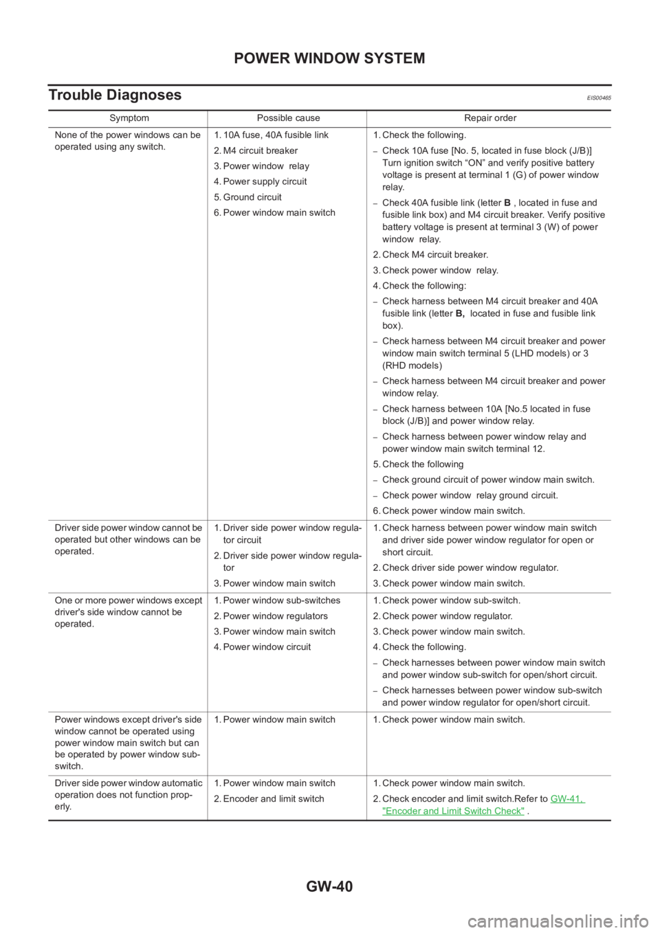
Symptom Possible cause Repair order
None of the power windows can be
operated using any switch.1. 10A fuse, 40A fusible link
2. M4 circuit breaker
3. Power window relay
4. Power supply circuit
5. Ground circuit
6. Power window main switch1. Check the following.
–Check 10A fuse [No. 5, located in fuse block (J/B)]
Turn ignition switch “ON” and verify positive battery
voltage is present at terminal 1 (G) of power window
relay.
–Check 40A fusible link (letter B , located in fuse and
fusible link box) and M4 circuit breaker. Verify positive
battery voltage is present at terminal 3 (W) of power
window relay.
2. Check M4 circuit breaker.
3. Check power window relay.
4. Check the following:
–Check harness between M4 circuit breaker and 40A
fusible link (letter B, located in fuse and fusible link
box).
–Check harness between M4 circuit breaker and power
window main switch terminal 5 (LHD models) or 3
(RHD models)
–Check harness between M4 circuit breaker and power
window relay.
–Check harness between 10A [No.5 located in fuse
block (J/B)] and power window relay.
–Check harness between power window relay and
power window main switch terminal 12.
5. Check the following
–Check ground circuit of power window main switch.
–Check power window relay ground circuit.
6. Check power window main switch.
Driver side power window cannot be
operated but other windows can be
operated.1. Driver side power window regula-
tor circuit
2. Driver side power window regula-
tor
3. Power window main switch1. Check harness between power window main switch
and driver side power window regulator for open or
short circuit.
2. Check driver side power window regulator.
3. Check power window main switch.
One or more power windows except
driver's side window cannot be
operated.1. Power window sub-switches
2. Power window regulators
3. Power window main switch
4. Power window circuit1. Check power window sub-switch.
2. Check power window regulator.
3. Check power window main switch.
4. Check the following.
–Check harnesses between power window main switch
and power window sub-switch for open/short circuit.
–Check harnesses between power window sub-switch
and power window regulator for open/short circuit.
Power windows except driver's side
window cannot be operated using
power window main switch but can
be operated by power window sub-
switch.1. Power window main switch 1. Check power window main switch.
Driver side power window automatic
operation does not function prop-
erly.1. Power window main switch
2. Encoder and limit switch1. Check power window main switch.
2. Check encoder and limit switch.Refer to GW-41,
"Encoder and Limit Switch Check" .
Page 3195 of 3833
POWER WINDOW SYSTEM
GW-43
C
D
E
F
G
H
J
K
L
MA
B
GW
5.CHECK ENCODER POWER SUPPLY
●Turn ignition switch ON.
●Check voltage between driver side power window regulator connector D5 terminal 5 (G/R) and ground.
OK or NG?
OK >> Replace power window regulator motor (front driver
side).
NG >> GO TO 6.
6.CHECK HARNESS CONTINUITY
●Turn ignition switch OFF.
●Disconnect power window main switch connector and front power window regulator connector.
●Check continuity between power window main switch connector D7 terminal 7 (G/R) (LHD models) or ter-
minal 1 (G/R) and front power window regulator D5 terminal 5 (G/R).
OK or NG?
OK >> Replace power window main switch.
NG >> Repair or replace harness between power window main
switch and front power window regulator. 5(G/R)–Ground :Approx. 10V
PIIA4763E
7(G/R)–5(G/R) : Continuity should exist.
1(G/R)–5(G/R) : Continuity should exist.
PIIA4764E
Page 3295 of 3833

REFRIGERATION SYSTEM
ATC-19
C
D
E
F
G
H
I
K
L
MA
B
AT C
V-6 Variable Displacement Compressor (With Gasoline Engine: CWV-615M
Compressor)
EJS000TF
GENERAL INFORMATION
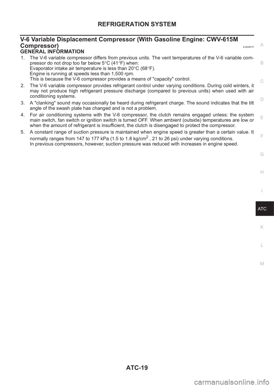
1. The V-6 variable compressor differs from previous units. The vent temperatures of the V-6 variable com-
pressor do not drop too far below 5°C (41°F) when:
Evaporator intake air temperature is less than 20°C (68°F).
Engine is running at speeds less than 1,500 rpm.
This is because the V-6 compressor provides a means of "capacity" control.
2. The V-6 variable compressor provides refrigerant control under varying conditions. During cold winters, it
may not produce high refrigerant pressure discharge (compared to previous units) when used with air
conditioning systems.
3. A "clanking" sound may occasionally be heard during refrigerant charge. The sound indicates that the tilt
angle of the swash plate has changed and is not a problem.
4. For air conditioning systems with the V-6 compressor, the clutch remains engaged unless: the system
main switch, fan switch or ignition switch is turned OFF. When ambient (outside) temperatures are low or
when the amount of refrigerant is insufficient, the clutch is disengaged to protect the compressor.
5. A constant range of suction pressure is maintained when engine speed is greater than a certain value. It
normally ranges from 147 to 177 kPa (1.5 to 1.8 kg/cm
2 , 21 to 26 psi) under varying conditions.
In previous compressors, however, suction pressure was reduced with increases in engine speed.
Page 3322 of 3833
ATC-46
TROUBLE DIAGNOSIS
Self-diagnosis Function
EJS001GX
DESCRIPTION
The self-diagnostic system diagnoses sensors, door motors, blower motor, etc. by system line. Refer to appli-
cable sections (items) for details. Shifting from normal control to the self-diagnostic system is accomplished by
starting the engine (turning the ignition switch from OFF to ON) and pressing OFF switch for at least 5 sec-
onds. The "OFF" switch must be pressed within 10 seconds after starting the engine (ignition switch is turned
ON). This system will be canceled by either pressing A/C switch or turning the ignition switch OFF. Shifting
from one step to another is accomplished by means of turning temperature dial, as required.
Additionally shifting from STEP 5 to AUXILIARY MECHANISM is accomplished by means of pushing (fan)
UP switch.
RJIA0490E
Page 3323 of 3833

TROUBLE DIAGNOSIS
ATC-47
C
D
E
F
G
H
I
K
L
MA
B
AT C
PROCEDURE
1.SET IN SELF-DIAGNOSTIC MODE
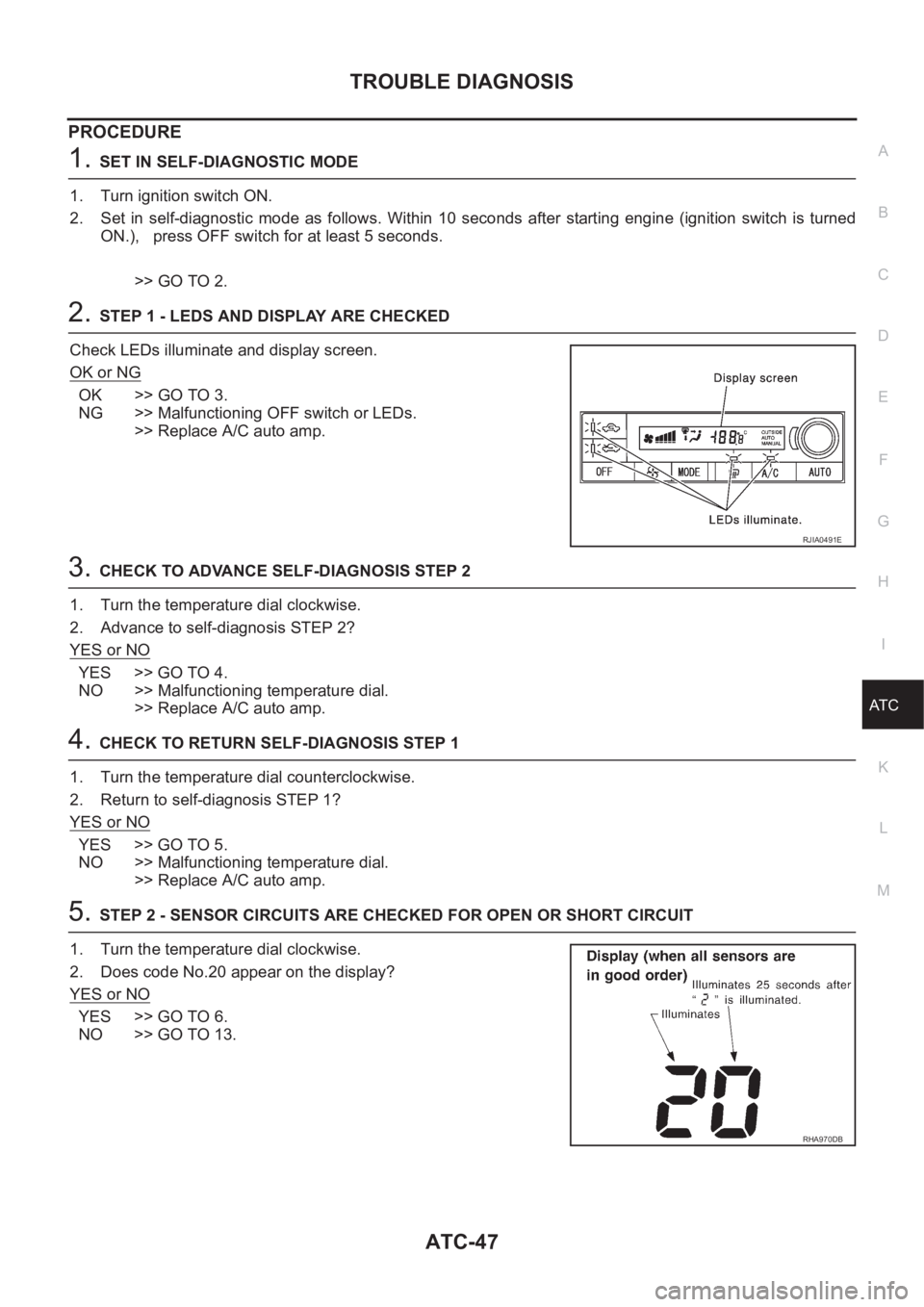
1. Turn ignition switch ON.
2. Set in self-diagnostic mode as follows. Within 10 seconds after starting engine (ignition switch is turned
ON.), press OFF switch for at least 5 seconds.
>> GO TO 2.
2.STEP 1 - LEDS AND DISPLAY ARE CHECKED
Check LEDs illuminate and display screen.
OK or NG
OK >> GO TO 3.
NG >> Malfunctioning OFF switch or LEDs.
>> Replace A/C auto amp.
3.CHECK TO ADVANCE SELF-DIAGNOSIS STEP 2
1. Turn the temperature dial clockwise.
2. Advance to self-diagnosis STEP 2?
YES or NO
YES >> GO TO 4.
NO >> Malfunctioning temperature dial.
>> Replace A/C auto amp.
4.CHECK TO RETURN SELF-DIAGNOSIS STEP 1
1. Turn the temperature dial counterclockwise.
2. Return to self-diagnosis STEP 1?
YES or NO
YES >> GO TO 5.
NO >> Malfunctioning temperature dial.
>> Replace A/C auto amp.
5.STEP 2 - SENSOR CIRCUITS ARE CHECKED FOR OPEN OR SHORT CIRCUIT
1. Turn the temperature dial clockwise.
2. Does code No.20 appear on the display?
YES or NO
YES >> GO TO 6.
NO >> GO TO 13.
RJIA0491E
RHA970DB
Page 3326 of 3833

ATC-50
TROUBLE DIAGNOSIS
10. CHECK AMBIENT SENSOR
Press (DEF) switch one time, temperature detected by ambient
sensor is indicated on the display.
NOTE:
If temperature shown on display greatly differs from actual tempera-
ture, check sensor circuit first, then inspect sensor.
OK or NG
OK >> GO TO 11.
NG >> Go to ATC-100, "
Ambient Sensor Circuit" .
11 . CHECK IN-VEHICLE SENSOR
Press (DEF) switch the second time, temperature detected by in-
vehicle sensor is indicated on the display.
NOTE:
If temperature shown on display greatly differs from actual tempera-
ture, check sensor circuit first, then inspect sensor.
OK or NG
OK >> GO TO 12.
NG >> Go to ATC-102, "
In-vehicle Sensor Circuit" .
12. CHECK INTAKE SENSOR
Press (DEF) switch the third time, temperature detected by intake
sensor is indicated on the display.
NOTE:
If temperature shown on display greatly differs from actual tempera-
ture, check sensor circuit first, then inspect sensor.
OK or NG
OK >> 1. Turn ignition switch OFF or (AUTO) switch ON.
2. END
NG >> Go to ATC-108, "
Intake Sensor Circuit" .
RHA551H
RHA552H
RJIA1944E
Page 3330 of 3833

ATC-54
TROUBLE DIAGNOSIS
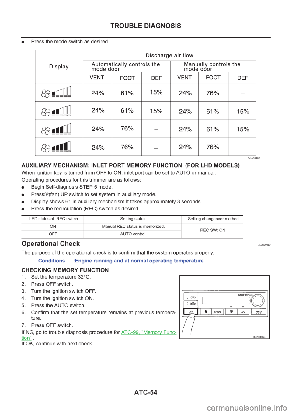
●Press the mode switch as desired.
AUXILIARY MECHANISM: INLET PORT MEMORY FUNCTION (FOR LHD MODELS)
When ignition key is turned from OFF to ON, inlet port can be set to AUTO or manual.
Operating procedures for this trimmer are as follows:
●Begin Self-diagnosis STEP 5 mode.
●Press (fan) UP switch to set system in auxiliary mode.
●Display shows 61 in auxiliary mechanism.It takes approximately 3 seconds.
●Press the recirculation (REC) switch as desired.
Operational CheckEJS001GY
The purpose of the operational check is to confirm that the system operates properly.
CHECKING MEMORY FUNCTION
1. Set the temperature 32°C.
2. Press OFF switch.
3. Turn the ignition switch OFF.
4. Turn the ignition switch ON.
5. Press the AUTO switch.
6. Confirm that the set temperature remains at previous tempera-
ture.
7. Press OFF switch.
If NG, go to trouble diagnosis procedure for AT C - 9 9 , "
Memory Func-
tion" .
If OK, continue with next check.
RJIA0040E
LED status of REC switch Setting status Setting changeover method
ON Manual REC status is memorized.
REC SW: ON
OFF AUTO control
Conditions :Engine running and at normal operating temperature
RJIA0496E
Page 3334 of 3833
ATC-58
TROUBLE DIAGNOSIS
DIAGNOSTIC PROCEDURE
SYMPTOM: A/C system does not come on.
1. CHECK POWER SUPPLY CIRCUIT FOR AUTO AMP.
OK or NG
OK >> GO TO 2.
NG >> Check 10A fuses (Nos. 15 and 28) and 15A fuses (Nos. 19 and 24) located in the fuse block (J/B).
●If fuses are OK, check for open circuit in wiring harness. Repair or replace as necessary.
●If fuses are NG, replace fuse and check wiring harness for short circuit. Repair or replace as
necessary.
2. CHECK GROUND CIRCUIT FOR AUTO AMP.
YES or NO
YES >> Replace auto amp. INSPECTION END
NO >> Repair or replace harness.
RJIA0504E
Terminals Ignition switch position
(+)
(-) OFF ACC ON
ConnectorTerminal
(Wire color)
M52 1 (BR/Y)
GroundApprox.
0VApprox.
0VApprox.
12V
M52 2 (L/B)Approx.
12VApprox.
12VApprox.
12V
M52 20 (L/W)Approx.
0VApprox.
12VApprox.
12V
RJIA0505E
Ohmmeter terminal
Continuity (+)
(-)
ConnectorTe r m i n a l ( W i r e
color)
M52 3 (B) Ground Yes
RJIA0506E