2001 NISSAN X-TRAIL ignition
[x] Cancel search: ignitionPage 3590 of 3833
DI-32
COMBINATION METERS (RHD MODELS)
SYMPTOM CHART
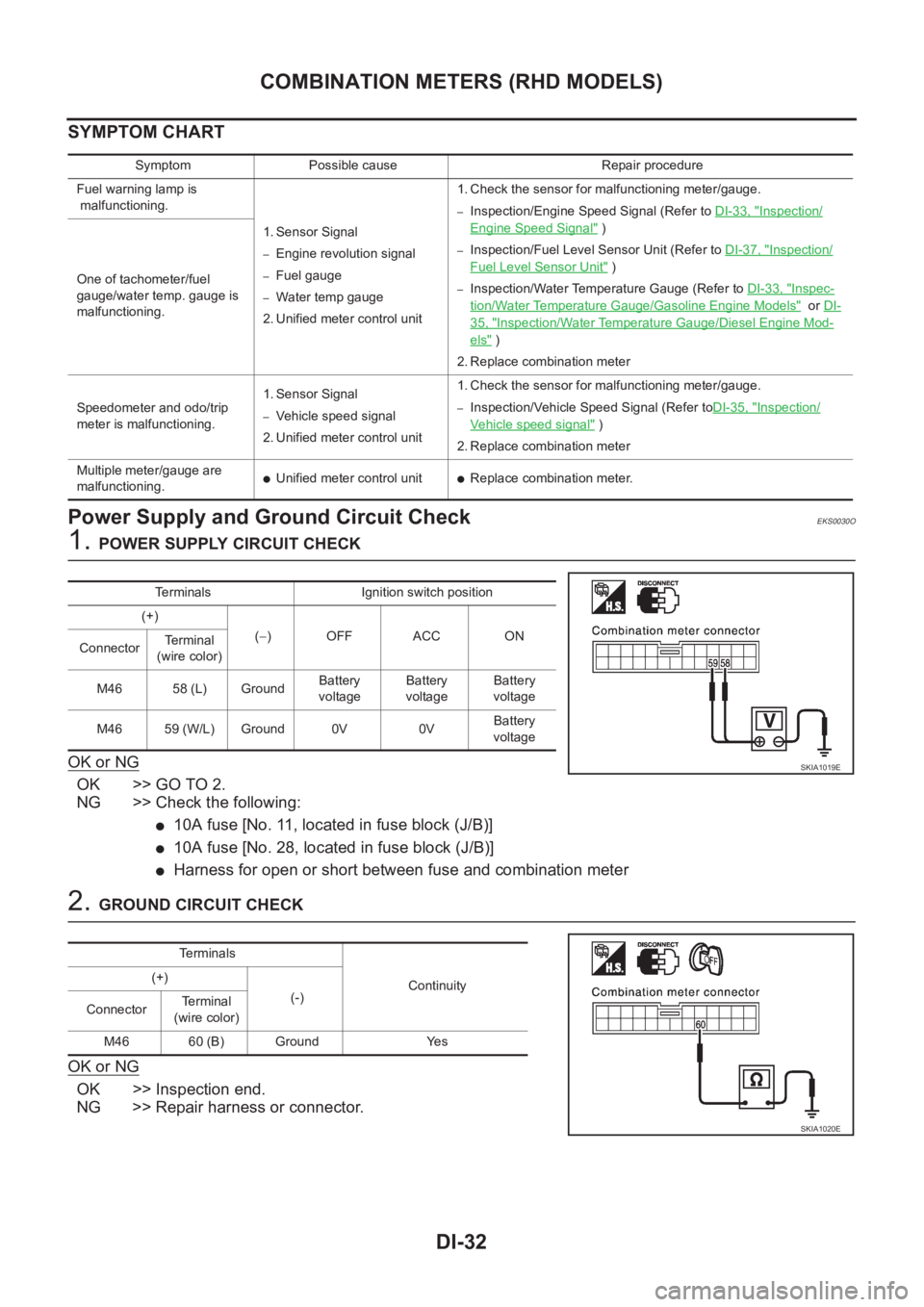
Power Supply and Ground Circuit CheckEKS0030O
1. POWER SUPPLY CIRCUIT CHECK
OK or NG
OK >> GO TO 2.
NG >> Check the following:
●10A fuse [No. 11, located in fuse block (J/B)]
●10A fuse [No. 28, located in fuse block (J/B)]
●Harness for open or short between fuse and combination meter
2. GROUND CIRCUIT CHECK
OK or NG
OK >> Inspection end.
NG >> Repair harness or connector.
Symptom Possible cause Repair procedure
Fuel warning lamp is
malfunctioning.
1. Sensor Signal
–Engine revolution signal
–Fuel gauge
–Water temp gauge
2. Unified meter control unit 1. Check the sensor for malfunctioning meter/gauge.
–Inspection/Engine Speed Signal (Refer to DI-33, "Inspection/
Engine Speed Signal" )
–Inspection/Fuel Level Sensor Unit (Refer to DI-37, "Inspection/
Fuel Level Sensor Unit" )
–Inspection/Water Temperature Gauge (Refer to DI-33, "Inspec-
tion/Water Temperature Gauge/Gasoline Engine Models" or DI-
35, "Inspection/Water Temperature Gauge/Diesel Engine Mod-
els" )
2. Replace combination meter One of tachometer/fuel
gauge/water temp. gauge is
malfunctioning.
Speedometer and odo/trip
meter is malfunctioning.1. Sensor Signal
–Vehicle speed signal
2. Unified meter control unit 1. Check the sensor for malfunctioning meter/gauge.–Inspection/Vehicle Speed Signal (Refer toDI-35, "Inspection/
Vehicle speed signal" )
2. Replace combination meter
Multiple meter/gauge are
malfunctioning.
●Unified meter control unit●Replace combination meter.
Terminals Ignition switch position
(+)
(−)OFF ACC ON
ConnectorTerminal
(wire color)
M46 58 (L) GroundBattery
voltageBattery
voltageBattery
voltage
M46 59 (W/L) Ground 0V 0VBattery
voltage
SKIA1019E
Te r m i n a l s
Continuity (+)
(-)
ConnectorTerminal
(wire color)
M46 60 (B) Ground Yes
SKIA1020E
Page 3593 of 3833
COMBINATION METERS (RHD MODELS)
DI-35
C
D
E
F
G
H
I
J
L
MA
B
DI
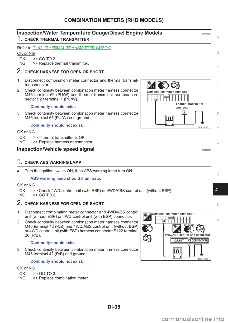
Inspection/Water Temperature Gauge/Diesel Engine ModelsEKS0030R
1.CHECK THERMAL TRANSMITTER
Refer to DI-42, "
THERMAL TRANSMITTER CHECK" .
OK or NG
OK >> GO TO 2.
NG >> Replace thermal transmitter.
2.CHECK HARNESS FOR OPEN OR SHORT
1. Disconnect combination meter connector and thermal transmit-
ter connector.
2. Check continuity between combination meter harness connector
M46 terminal 66 (PU/W) and thermal transmitter harness con-
nector F23 terminal 1 (PU/W).
3. Check continuity between combination meter harness connector
M46 terminal 66 (PU/W) and ground.
OK or NG
OK >> Thermal transmitter is OK.
NG >> Replace harness or connector.
Inspection/Vehicle speed signalEKS0030S
1.CHECK ABS WARNING LAMP
●Turn the ignition switch ON, then ABS warning lamp turn ON.
OK or NG
OK >> Check 4WD control unit (with ESP) or 4WD/ABS control unit (without ESP).
NG >> GO TO 2.
2.CHECK HARNESS FOR OPEN OR SHORT
1. Disconnect combination meter connector and 4WD/ABS control
unit (without ESP) or 4WD control unit (with ESP) connector.
2. Check continuity between combination meter harness connector
M45 terminal 42 (R/B) and 4WD/ABS control unit (without ESP)
or 4WD control unit (with ESP) harness connector E122 terminal
20 (R/B).
3. Check continuity between combination meter harness connector
M45 terminal 42 (R/B) and ground.
OK or NG
OK >> GO TO 3.
NG >> Replace combination meter.Continuity should exist.
Continuity should not exist.
SKIA1024E
ABS warning lamp should illuminate.
Continuity should exist.
Continuity should not exist.
SKIA1025E
Page 3595 of 3833
COMBINATION METERS (RHD MODELS)
DI-37
C
D
E
F
G
H
I
J
L
MA
B
DI
Inspection/Fuel Level Sensor UnitEKS0030T
FUEL LEVEL SENSOR UNIT
The following symptoms do not indicate a malfunction.
●Depending on vehicle posture or driving circumstance, the fuel level in the tank varies, and the pointer
may fluctuate.
●If the vehicle is fueled with the ignition switch ON, the pointer will move slowly.
LOW-FUEL WARNING LAMP
Depending on vehicle posture or driving circumstance, the fuel level in the tank varies, and the warning lamp
ON timing may be changed.
1.DIAGNOSIS MODE INSPECTION
Preform the combination meter diagnosis mode. Refer to DI-30, "
Meter/Gauge Operation and Odo/Trip Meter
Segment Check in Diagnosis Mode" .
OK or NG
OK >> GO TO 2.
NG >> Replace combination meter.
2.HARNESS CONNECTOR INSPECTION
1. Turn the ignition switch OFF.
2. Check combination meter, fuel level sensor unit and terminals (meter-side, module-side, and harness-
side) for poor connection and bend.
OK or NG
OK >> GO TO 3.
NG >> Repair terminals or connectors.
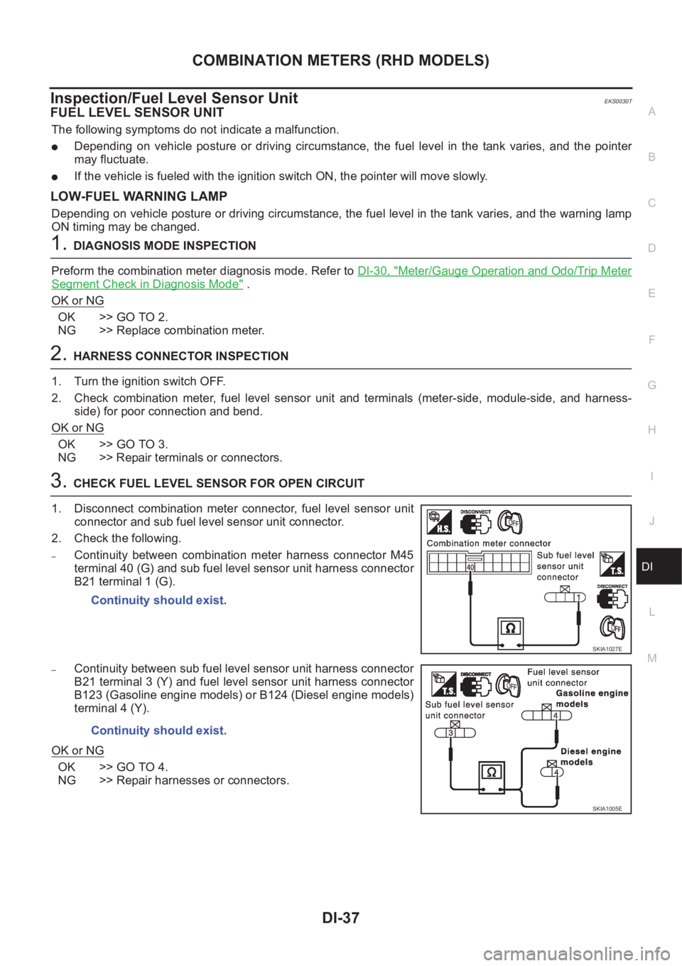
3.CHECK FUEL LEVEL SENSOR FOR OPEN CIRCUIT
1. Disconnect combination meter connector, fuel level sensor unit
connector and sub fuel level sensor unit connector.
2. Check the following.
–Continuity between combination meter harness connector M45
terminal 40 (G) and sub fuel level sensor unit harness connector
B21 terminal 1 (G).
–Continuity between sub fuel level sensor unit harness connector
B21 terminal 3 (Y) and fuel level sensor unit harness connector
B123 (Gasoline engine models) or B124 (Diesel engine models)
terminal 4 (Y).
OK or NG
OK >> GO TO 4.
NG >> Repair harnesses or connectors.Continuity should exist.
SKIA1027E
Continuity should exist.
SKIA1005E
Page 3597 of 3833
COMBINATION METERS (RHD MODELS)
DI-39
C
D
E
F
G
H
I
J
L
MA
B
DI
The Fuel Gauge Does Not Move to Full-position.EKS0030V
1.QUESTION 1
Does it take a long time for the pointer to move to Full-position?
Ye s o r N o
Ye s > > G O T O 2 .
No >> GO TO 3.
2.QUESTION 2
Was the vehicle fueled with the ignition switch ON?
Ye s o r N o
Yes >> Be sure to fuel the vehicle with the ignition switch OFF. Otherwise it will take a long time to move
to Full-position because of the characteristic of the fuel gauge.
No >> GO TO 3.
3.QUESTION 3
Is the floor or the vehicle inclined?
Ye s o r N o
Yes >> It may not be filled fully.
No >> GO TO 4.
4.QUESTION 4
During driving, does the fuel gauge pointer move gradually toward E-position?
Ye s o r N o
Yes >> Check the components. Refer to DI-41, "Electrical Components Inspection" .
No >> The float arm may interfere or bind with any of the components in the fuel tank.
The Fuel Gauge Does Not Work.EKS0030W
1.HARNESS CONNECTOR INSPECTION
1. Turn the ignition switch OFF.
2. Check combination meter, fuel level sensor unit, sub fuel level sensor unit and terminals (meter-side,
module-side, and harness-side) for poor connection and bend.
OK or NG
OK >> GO TO 2.
NG >> Repair connector.
2.CHECK INSTALLATION CONDITION
Check fuel level sensor unit or sub fuel level sensor unit installation (refer toFL-4, "
FUEL LEVEL SENSOR
UNIT, FUEL FILTER AND FUEL PUMP ASSEMBLY" for QR engine models or FL-17, "FUEL LEVEL SEN-
SOR UNIT" for YD engine models, and check whether the float arm interferes or binds with any components
inside the arm.
OK or NG
OK >> Fuel level sensor unit is OK.
NG >> Check fuel level sensor unit or sub fuel level sensor unit. Refer to DI-41, "
Electrical Components
Inspection" .
Page 3614 of 3833
DI-56
WARNING LAMPS
Electrical Components Inspection
EKS002HK
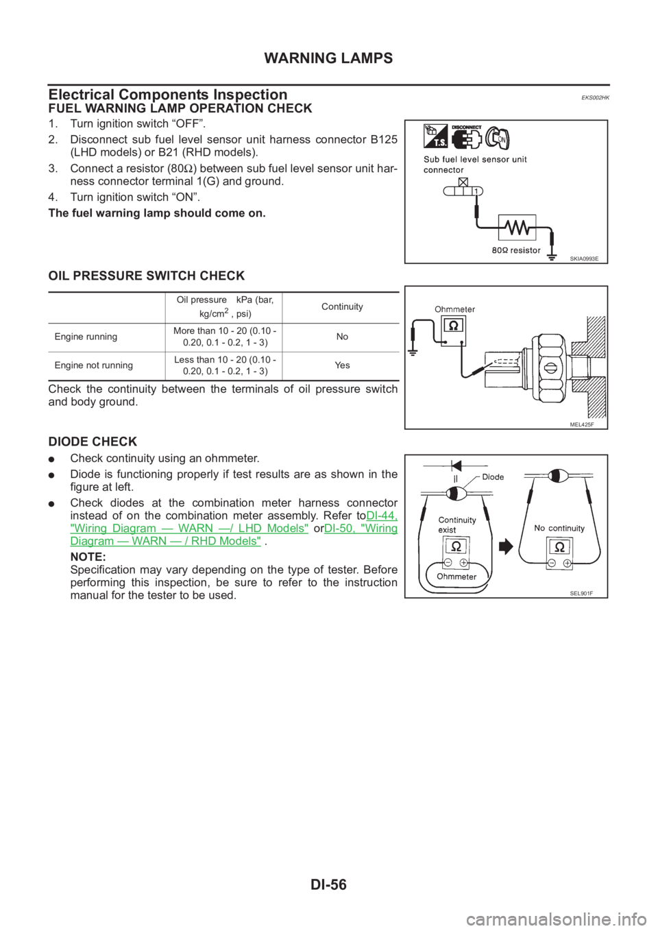
FUEL WARNING LAMP OPERATION CHECK
1. Turn ignition switch “OFF”.
2. Disconnect sub fuel level sensor unit harness connector B125
(LHD models) or B21 (RHD models).
3. Connect a resistor (80Ω) between sub fuel level sensor unit har-
ness connector terminal 1(G) and ground.
4. Turn ignition switch “ON”.
The fuel warning lamp should come on.
OIL PRESSURE SWITCH CHECK
Check the continuity between the terminals of oil pressure switch
and body ground.
DIODE CHECK
●Check continuity using an ohmmeter.
●Diode is functioning properly if test results are as shown in the
figure at left.
●Check diodes at the combination meter harness connector
instead of on the combination meter assembly. Refer toDI-44,
"Wiring Diagram — WARN —/ LHD Models" orDI-50, "Wiring
Diagram — WARN — / RHD Models" .
NOTE:
Specification may vary depending on the type of tester. Before
performing this inspection, be sure to refer to the instruction
manual for the tester to be used.
SKIA0993E
Oil pressure kPa (bar,
kg/cm2 , psi)Continuity
Engine runningMore than 10 - 20 (0.10 -
0.20, 0.1 - 0.2, 1 - 3)No
Engine not runningLess than 10 - 20 (0.10 -
0.20, 0.1 - 0.2, 1 - 3)Ye s
MEL425F
SEL901F
Page 3616 of 3833
DI-58
WARNING CHIME
WARNING CHIME
PFP:24814
System DescriptionEKS002XF
POWER SUPPLY AND GROUND CIRCUIT
Power is supplied at all times
●to combination switch terminal 11 and
●to daytime light control unit terminal 1 (with daytime light system)
●through 10A fuse (No.31, located in fuse and fusible link box), and
●to key switch terminal 1 and
●to time control unit terminal 1
●through 10A fuse [No.28, located in the fuse block (J/B)].
With ignition switch in ON or START position, power is supplied
●to time control unit terminal 17
●through 10A fuse [No.5, located in the fuse block (J/B)].
Ground is supplied
●to time control unit terminal 16
●through body grounds M27 and M70.
IGNITION KEY WARNING CHIME
With ignition switch in OFF or ACC position, and the driver's door open and driver’s door locked, the warning
chime will sound. Power is supplied
●to time control unit terminal 18
●through key switch terminal 2 and
Ground is supplied
●to time control unit terminal 28
●through front door lock actuator (driver side) terminal 5
Front door lock actuator (driver side) terminal 2 is grounded through body grounds M27 and M70, and
Ground is supplied
●to time control unit terminal 30
●through front door switch (driver side) terminal 2.
Front door switch (driver side) terminal 3 is grounded through body grounds B8 and B18.
LIGHT WARNING CHIME
With ignition switch OFF position, driver's door open, and lighting switch in 1ST or 2ND position, warning
chime will sound. Power is supplied
●from the lighting switch terminal 12 or daytime light control unit terminal 11 (with daytime light system)
●to time control unit terminal 19.
Ground is supplied
●to time control unit terminal 30
●through front door switch (driver side) terminal 2.
Front door switch (driver side) terminal 3 is grounded through body grounds B8 and B18.
SEAT BELT WARNING CHIME
When the vehicle speed exceeds 25 km/h (16MPH) with driver side or passenger side seat belt unfastened
(seat belt switch ON), warning chime will sound. Refer to SB-6, "
SEAT BELT WARNING SYSTEM" .
Page 3620 of 3833
DI-62
WARNING CHIME
Power Supply and Ground Circuit Check
EKS002YF
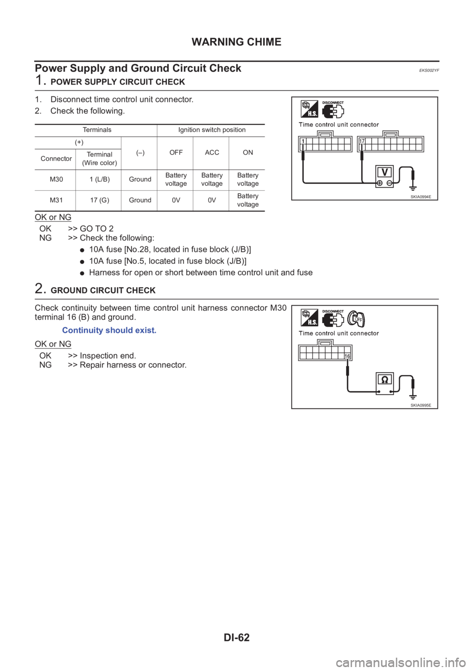
1. POWER SUPPLY CIRCUIT CHECK
1. Disconnect time control unit connector.
2. Check the following.
OK or NG
OK >> GO TO 2
NG >> Check the following:
●10A fuse [No.28, located in fuse block (J/B)]
●10A fuse [No.5, located in fuse block (J/B)]
●Harness for open or short between time control unit and fuse
2. GROUND CIRCUIT CHECK
Check continuity between time control unit harness connector M30
terminal 16 (B) and ground.
OK or NG
OK >> Inspection end.
NG >> Repair harness or connector.
Terminals Ignition switch position
(+)
(–) OFF ACC ON
ConnectorTerminal
(Wire color)
M30 1 (L/B) GroundBattery
voltageBattery
voltageBattery
voltage
M31 17 (G) Ground 0V 0VBattery
voltage
SKIA0994E
Continuity should exist.
SKIA0995E
Page 3632 of 3833
WW-4
FRONT WIPER AND WASHER SYSTEM
FRONT WIPER AND WASHER SYSTEM
PFP:28810
System DescriptionEKS0032N
WIPER OPERATION
The wiper switch is controlled by a lever built into the combination switch.
There are three wiper switch positions:
●LO speed
●HI speed
●INT (Intermittent)
With the ignition switch in the ON or START position, power is supplied
●through 20A fuse [No. 6, located in the fuse block (J/B)]
●to front wiper motor terminal 4.
LOW AND HIGH SPEED WIPER OPERATION
Ground is supplied to front wiper and washer switch terminal 17 through body grounds E24 and E50.
When the wiper switch is placed in the LO position, ground is supplied
●through terminal 14 of the front wiper and washer switch
●to front wiper motor terminal 3.
With power and ground supplied, the wiper motor operates at low speed.
When the wiper switch is placed in the HI position, ground is supplied
●through terminal 16 of the front wiper and washer switch
●to front wiper motor terminal 1.
With power and ground supplied, the wiper motor operates at high speed.
AUTO STOP OPERATION
With wiper switch turned OFF, wiper motor will continue to operate until wiper arms reach windshield base.
When wiper arms are not located at base of windshield with wiper switch OFF, ground is provided
●from terminal 14 of the front wiper and washer switch
●to front wiper motor terminal 3, in order to continue wiper motor operation at low speed.
Ground is also supplied
●through terminal 13 of the front wiper and washer switch
●to front wiper motor terminal 2
●through terminal 6 of the front wiper motor, and
●through body grounds E24 and E50.
When wiper arms reach base of windshield, front wiper motor terminals 4 and 2 are connected instead of ter-
minals 6 and 2. Wiper motor will then stop wiper arms at the STOP position.
INTERMITTENT OPERATION
The front wiper motor operates the wiper arms one time at low speed at a set interval of approximately 1 to 13
seconds. This feature is controlled by the wiper amplifier (INT SW) combined with front wiper and washer
switch.
When the wiper switch is placed in the INT position, ground is supplied to wiper amplifier.
The desired interval time is input to wiper amplifier (INT VR) from wiper volume switch combined with front
wiper and washer switch.
Then intermittent ground is supplied
●through wiper amplifier (OUTPUT) and
●through terminal 14 of front wiper and washer switch
●to front wiper motor terminal 3
The wiper motor operates at low speed at the desired interval.
WASHER OPERATION
With the ignition switch in the ON or START position, power is supplied
●through 20A fuse [No. 6, located in the fuse block (J/B)]
●to front washer motor terminal 1.
When the lever is pulled to the WASH position, ground is supplied