Page 3635 of 3833

FRONT WIPER AND WASHER SYSTEM
WW-7
C
D
E
F
G
H
I
J
L
MA
B
WW
Terminal and Reference Values for Combination SwitchEKS0032P
Removal and Installation for Front Wiper Arms, Adjustment for Wiper Arms
Stop Location
EKS0032Q
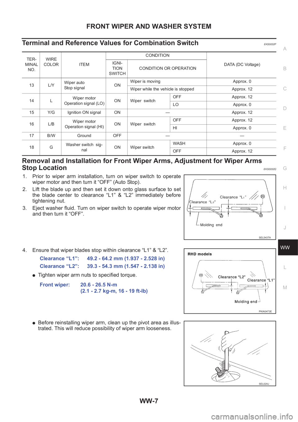
1. Prior to wiper arm installation, turn on wiper switch to operate
wiper motor and then turn it “OFF” (Auto Stop).
2. Lift the blade up and then set it down onto glass surface to set
the blade center to clearance “L1” & “L2” immediately before
tightening nut.
3. Eject washer fluid. Turn on wiper switch to operate wiper motor
and then turn it “OFF”.
4. Ensure that wiper blades stop within clearance “L1” & “L2”.
●Tighten wiper arm nuts to specified torque.
●Before reinstalling wiper arm, clean up the pivot area as illus-
trated. This will reduce possibility of wiper arm looseness.
TER-
MINAL
NO.WIRE
COLOR ITEM CONDITION
DATA (DC Voltage) IGNI-
TION
SWITCHCONDITION OR OPERATION
13 L/YWiper auto
Stop signalONWiper is moving Approx. 0
Wiper while the vehicle is stopped Approx. 12
14 LWiper motor
Operation signal (LO)ON Wiper switchOFF Approx. 12
LO Approx. 0
15 Y/G Ignition ON signal ON — Approx. 12
16 L/BWiper motor
Operation signal (HI)ON Wiper switchOFF Approx. 12
HI Approx. 0
17 B/W Ground OFF — —
18 GWasher switch sig-
nalON Wiper switchWASH Approx. 0
OFF Approx. 12
SEL543TA
Clearance “L1”: 49.2 - 64.2 mm (1.937 - 2.528 in)
Clearance “L2”: 39.3 - 54.3 mm (1.547 - 2.138 in)
Front wiper: 20.6 - 26.5 N-m
(2.1 - 2.7 kg-m, 16 - 19 ft-lb)
PKIA0473E
SEL024J
Page 3647 of 3833

HEADLAMP WASHER
WW-19
C
D
E
F
G
H
I
J
L
MA
B
WW
HEADLAMP WASHERPFP:28620
System DescriptionEKS0036H
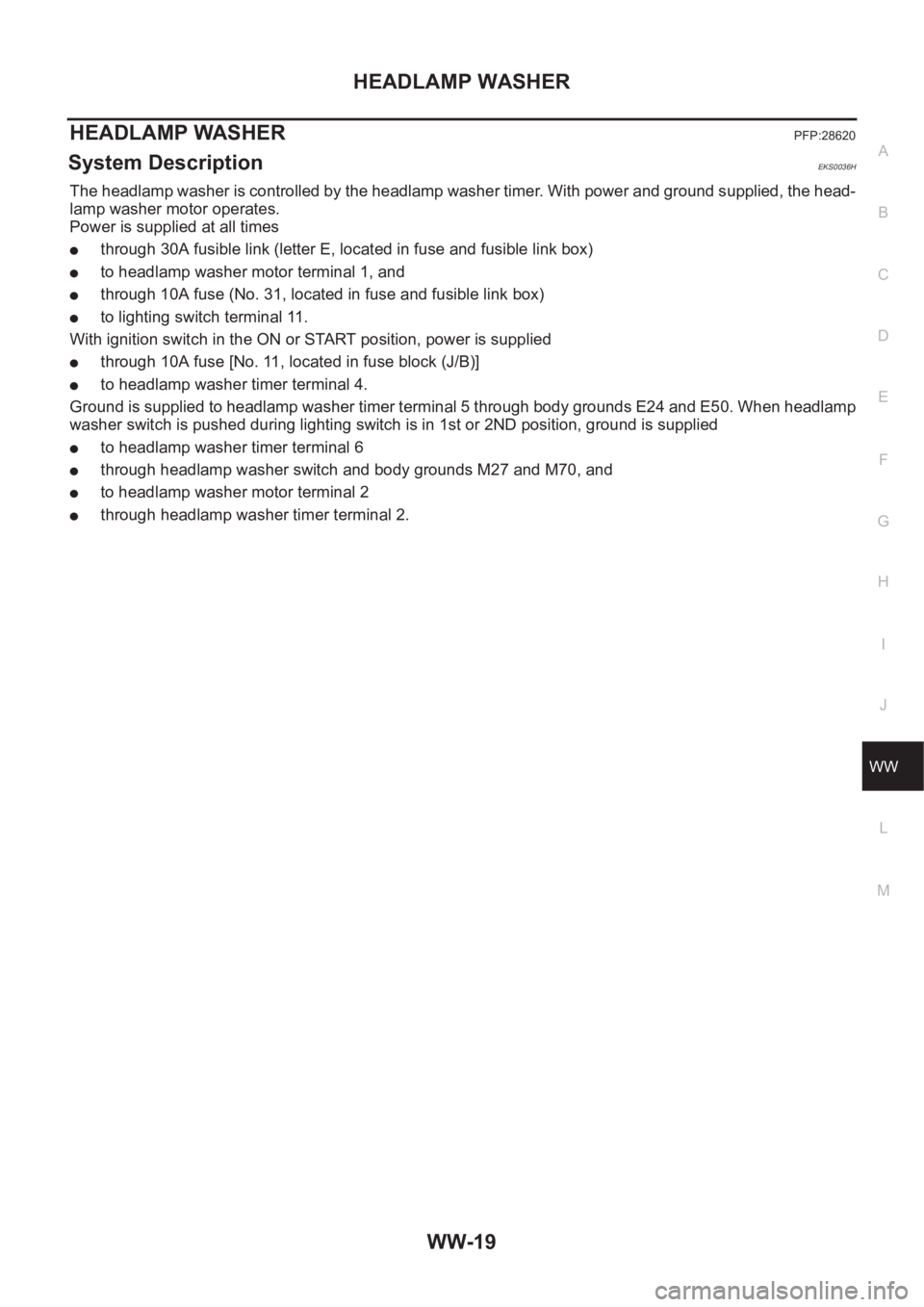
The headlamp washer is controlled by the headlamp washer timer. With power and ground supplied, the head-
lamp washer motor operates.
Power is supplied at all times
●through 30A fusible link (letter E, located in fuse and fusible link box)
●to headlamp washer motor terminal 1, and
●through 10A fuse (No. 31, located in fuse and fusible link box)
●to lighting switch terminal 11.
With ignition switch in the ON or START position, power is supplied
●through 10A fuse [No. 11, located in fuse block (J/B)]
●to headlamp washer timer terminal 4.
Ground is supplied to headlamp washer timer terminal 5 through body grounds E24 and E50. When headlamp
washer switch is pushed during lighting switch is in 1st or 2ND position, ground is supplied
●to headlamp washer timer terminal 6
●through headlamp washer switch and body grounds M27 and M70, and
●to headlamp washer motor terminal 2
●through headlamp washer timer terminal 2.
Page 3659 of 3833

TIME CONTROL UNIT
BCS-3
C
D
E
F
G
H
I
J
L
MA
B
BCS
TIME CONTROL UNITPFP:28491
DescriptionEKS002ZU
OUTLINE
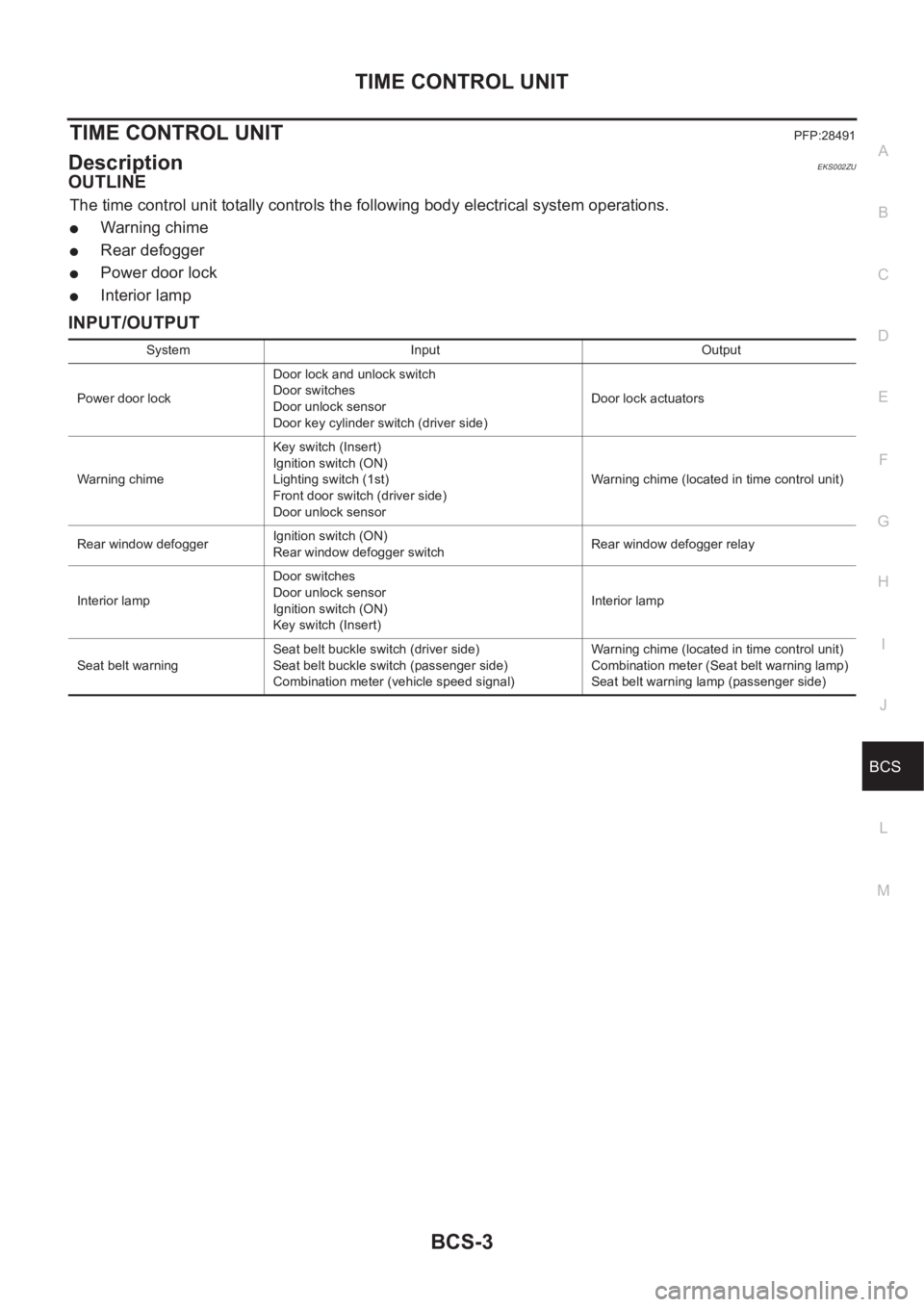
The time control unit totally controls the following body electrical system operations.
●Warning chime
●Rear defogger
●Power door lock
●Interior lamp
INPUT/OUTPUT
System Input Output
Power door lockDoor lock and unlock switch
Door switches
Door unlock sensor
Door key cylinder switch (driver side)Door lock actuators
Warning chimeKey switch (Insert)
Ignition switch (ON)
Lighting switch (1st)
Front door switch (driver side)
Door unlock sensorWarning chime (located in time control unit)
Rear window defoggerIgnition switch (ON)
Rear window defogger switchRear window defogger relay
Interior lampDoor switches
Door unlock sensor
Ignition switch (ON)
Key switch (Insert)Interior lamp
Seat belt warningSeat belt buckle switch (driver side)
Seat belt buckle switch (passenger side)
Combination meter (vehicle speed signal)Warning chime (located in time control unit)
Combination meter (Seat belt warning lamp)
Seat belt warning lamp (passenger side)
Page 3661 of 3833

TIME CONTROL UNIT
BCS-5
C
D
E
F
G
H
I
J
L
MA
B
BCS
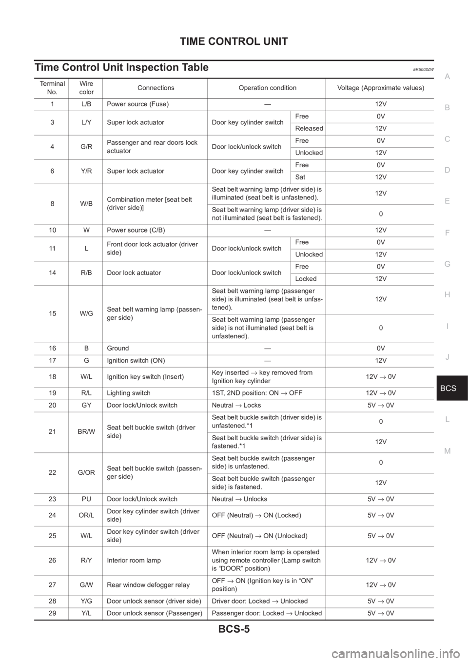
Time Control Unit Inspection TableEKS002ZW
Terminal
No.Wire
colorConnections Operation condition Voltage (Approximate values)
1 L/B Power source (Fuse) — 12V
3 L/Y Super lock actuator Door key cylinder switchFree 0V
Released 12V
4G/RPassenger and rear doors lock
actuatorDoor lock/unlock switchFree 0V
Unlocked 12V
6 Y/R Super lock actuator Door key cylinder switchFree 0V
Sat 12V
8W/BCombination meter [seat belt
(driver side)]Seat belt warning lamp (driver side) is
illuminated (seat belt is unfastened).12V
Seat belt warning lamp (driver side) is
not illuminated (seat belt is fastened).0
10 W Power source (C/B) — 12V
11 LFront door lock actuator (driver
side)Door lock/unlock switchFree 0V
Unlocked 12V
14 R/B Door lock actuator Door lock/unlock switchFree 0V
Locked 12V
15 W/GSeat belt warning lamp (passen-
ger side)Seat belt warning lamp (passenger
side) is illuminated (seat belt is unfas-
tened).12V
Seat belt warning lamp (passenger
side) is not illuminated (seat belt is
unfastened).0
16 B Ground — 0V
17 G Ignition switch (ON) — 12V
18 W/L Ignition key switch (Insert)Key inserted → key removed from
Ignition key cylinder12V → 0V
19 R/L Lighting switch 1ST, 2ND position: ON → OFF 12V → 0V
20 GY Door lock/Unlock switch Neutral → Locks 5V → 0V
21 BR/WSeat belt buckle switch (driver
side)Seat be lt buckle switch (d river side) is
unfastened.*10
Seat be lt buckle switch (d river side) is
fastened.*112V
22 G/ORSeat belt buckle switch (passen-
ger side)Seat belt buckle switch (passenger
side) is unfastened.0
Seat belt buckle switch (passenger
side) is fastened.12V
23 PU Door lock/Unlock switch Neutral → Unlocks 5V → 0V
24 OR/LDoor key cylinder switch (driver
side)OFF (Neutral) → ON (Locked) 5V → 0V
25 W/LDoor key cylinder switch (driver
side)OFF (Neutral) → ON (Unlocked) 5V → 0V
26 R/Y Interior room lampWhen interior room lamp is operated
using remote controller (Lamp switch
is “DOOR” position)12V → 0V
27 G/W Rear window defogger relayOFF→ ON (Ignition key is in “ON”
position)12V → 0V
28 Y/G Door unlock sensor (driver side) Driver door: Locked → Unlocked 5V → 0V
29 Y/L Door unlock sensor (Passenger) Passenger door: Locked → Unlocked 5V → 0V
Page 3662 of 3833
BCS-6
TIME CONTROL UNIT
NOTE:
*1: When seat pressure switch is ON.
*2: Wire color is different depending on vehicle. Each wire color are as follows:
30 R Front door switch (driver side) OFF (closed) → ON (open) 5V → 0V
31 R/W Passenger and rear doors switch OFF (closed) → ON (open) 5V → 0V
32 OR Multi-remote control unitRemote controller lock button is
pushed.
(Ignition switch is not at “ON” position)0V → 5V
33 P/L Multi-remote control unitRemote controller unlock button is
pushed.
(Ignition switch is not at “ON” position)0V → 5V
34 B/Y NATS release signal Ignition switch ON→OFF 0V→5V
35 LG/B Rear window defogger switch OFF → ON 5V → 0V
36 *2 Combination meterWhen the vehicle speed is approx.
40km (25MPH). Te r m i n a l
No.Wire
colorConnections Operation condition Voltage (Approximate values)
ELF1080D
Vehicle Wire color
A/T models :L/W
M/T models with gasoline engine :L/Y
Diesel engine models :L/B
Page 3671 of 3833
![NISSAN X-TRAIL 2001 Service Repair Manual CAN SYSTEM (FOR A/T MODELS)
LAN-9
[CAN]
C
D
E
F
G
H
I
J
L
MA
B
LAN
CHECK SHEET RESULTS (EXAMPLE)
INSPECTION
Proceed trouble diagnosis according to the check sheet results (example).
Case 1:Replace ECM NISSAN X-TRAIL 2001 Service Repair Manual CAN SYSTEM (FOR A/T MODELS)
LAN-9
[CAN]
C
D
E
F
G
H
I
J
L
MA
B
LAN
CHECK SHEET RESULTS (EXAMPLE)
INSPECTION
Proceed trouble diagnosis according to the check sheet results (example).
Case 1:Replace ECM](/manual-img/5/57405/w960_57405-3670.png)
CAN SYSTEM (FOR A/T MODELS)
LAN-9
[CAN]
C
D
E
F
G
H
I
J
L
MA
B
LAN
CHECK SHEET RESULTS (EXAMPLE)
INSPECTION
Proceed trouble diagnosis according to the check sheet results (example).
Case 1:Replace ECM.
Case 2:Replace TCM.
Case 3:Check CAN communication circuit. Refer to LAN-9, "
CAN Communication Circuit Check" .
CAN Communication Circuit CheckEKS002AH
1.CHECK CONNECTOR
1. Turn ignition switch OFF.
2. Check following terminals and connector for damage, bend and loose connection (control module-side
and harness-side).
●TCM.
●ECM.
OK or NG
OK >> GO TO 2.
NG >> Repair terminal or connector.
2.CHECK HARNESS FOR SHORT CIRCUIT
1. Disconnect ECM connector and TCM connector.
2. Check the following.
●QR20DE engine models:
Continuity between ECM harness connector F43 terminals 33
(B/W) and 34 (L/R).
●QR25DE engine models:
Continuity between ECM harness connector F43 terminals 33
(W/B) and 34 (L/R).
OK or NG
OK >> GO TO 3.
NG >> Repair harness between ECM and TCM.
SKIA0887E
33 (B/W) – 34 (L/R)
(QR20DE engine models): Continuity should not
exist.
33 (W/B) – 34 (L/R)
(QR25DE engine models): Continuity should not
exist.
SKIA0888E
Page 3679 of 3833
![NISSAN X-TRAIL 2001 Service Repair Manual CAN SYSTEM (FOR M/T MODELS)
LAN-17
[CAN]
C
D
E
F
G
H
I
J
L
MA
B
LAN
INSPECTION
Proceed trouble diagnosis according to the check sheet results (example).
Case 1: Replace ECM.
Case 2: Replace ESP/TCS/AB NISSAN X-TRAIL 2001 Service Repair Manual CAN SYSTEM (FOR M/T MODELS)
LAN-17
[CAN]
C
D
E
F
G
H
I
J
L
MA
B
LAN
INSPECTION
Proceed trouble diagnosis according to the check sheet results (example).
Case 1: Replace ECM.
Case 2: Replace ESP/TCS/AB](/manual-img/5/57405/w960_57405-3678.png)
CAN SYSTEM (FOR M/T MODELS)
LAN-17
[CAN]
C
D
E
F
G
H
I
J
L
MA
B
LAN
INSPECTION
Proceed trouble diagnosis according to the check sheet results (example).
Case 1: Replace ECM.
Case 2: Replace ESP/TCS/ABS control unit.
Case 3: Replace 4WD control unit.
Case 4: Check harness between steering wheel angle sensor and 4WD control unit. Refer to LAN-17, "
Circuit
Check Between Steering Wheel Angle Sensor and 4WD Control Unit" .
Case 5: Check ECM circuit. Refer to LAN-18, "
ECM Circuit Check" .
Case 6: Check 4WD control unit circuit. Refer to LAN-19, "
4WD Control Unit Circuit Check" .
Case 7: Check Steering wheel angle sensor circuit. Refer to LAN-20, "
Steering Wheel Angle Sensor Circuit
Check" .
Case 8: Check ESP/TCS/ABS control unit circuit. Refer to LAN-20, "
ESP/TCS/ABS Control Unit Circuit
Check" .
Case 9: Check CAN communication circuit. Refer to LAN-21, "
CAN Communication Circuit Check" .
Circuit Check Between Steering Wheel Angle Sensor and 4WD Control UnitEKS002FO
1.CHECK CONNECTOR
1. Turn ignition switch OFF.
2. Check following terminals and connector for damage, bend and loose connection (control unit-side, sen-
sor-side and harness-side).
●4WD control unit.
●Steering wheel angle sensor.
●Between 4WD control unit and steering wheel angle sensor.
OK or NG
OK >> GO TO 2.
NG >> Repair terminal or connector.
SKIA0927E
Page 3680 of 3833
![NISSAN X-TRAIL 2001 Service Repair Manual LAN-18
[CAN]
CAN SYSTEM (FOR M/T MODELS)
2. CHECK HARNESS FOR OPEN CIRCUIT
1. Disconnect steering wheel angle sensor connector and harness connector M75.
2. Check continuity between steering wheel ang NISSAN X-TRAIL 2001 Service Repair Manual LAN-18
[CAN]
CAN SYSTEM (FOR M/T MODELS)
2. CHECK HARNESS FOR OPEN CIRCUIT
1. Disconnect steering wheel angle sensor connector and harness connector M75.
2. Check continuity between steering wheel ang](/manual-img/5/57405/w960_57405-3679.png)
LAN-18
[CAN]
CAN SYSTEM (FOR M/T MODELS)
2. CHECK HARNESS FOR OPEN CIRCUIT
1. Disconnect steering wheel angle sensor connector and harness connector M75.
2. Check continuity between steering wheel angle sensor harness
connector M81 terminals 4 (W), 5 (R) and harness connector
M75 terminals 8 (W), 19 (R).
OK or NG
OK >> GO TO 3.
NG >> Repair harness.
3. CHECK HARNESS FOR OPEN CIRCUIT
1. Disconnect 4WD control unit connector.
2. Check continuity between harness connector E116 terminals 8
(W), 19 (R) and 4WD control unit harness connector E122 termi-
nals 48 (W), 39 (R).
OK or NG
OK >> Reconnect all connectors to perform “SELF-DIAG
RESULTS” and “DATA MONITOR” for “ENGINE”, “ALL
MODE 4WD” and “ABS” displayed on CONSULT-II.
Refer to the following:
●EC-854, "DTC U1000 CAN COMMUNICATION LINE"
(QR20 WITH EURO-OBD) for “ENGINE”
●EC-1199, "DTC U1000 CAN COMMUNICATION LINE" (QR20 WITHOUT EURO-OBD) for
“ENGINE”
●EC-1448, "DTC U1000 CAN COMMUNICATION LINE" (YD) for “ENGINE”
●TF-53, "CAN COMMUNICATION SYSTEM" for “ALL MODE 4WD”
●BRC-110, "Inspection 15 CAN Communication Circuit, ESP/TCS/ABS Control Unit and Steer-
ing Wheel Angle Sensor" for “ABS”
NG >> Repair harness.
ECM Circuit CheckEKS002FQ
1. CHECK CONNECTOR
1. Turn ignition switch OFF.
2. Check following terminals and connector for damage, bend and loose connection (control module-side
and harness-side).
●ECM.
●Harness connector F41 (QR20DE engine models).
●Harness connector M61 (QR20DE engine models).
●Harness connector F29 (YD22DDTi engine models).
●Harness connector M64 (YD22DDTi engine models).
OK or NG
OK >> GO TO 2.
NG >> Repair terminal or connector.4 (W) – 8 (W) : Continuity should exist.
5 (R) – 19 (R) : Continuity should exist.
SKIA0928E
8 (W) – 48 (W) : Continuity should exist.
19 (R) – 39 (R) : Continuity should exist.
SKIA0929E