2001 NISSAN X-TRAIL ignition
[x] Cancel search: ignitionPage 2891 of 3833
![NISSAN X-TRAIL 2001 Service Repair Manual TROUBLE DIAGNOSIS
BRC-107
[ESP/TCS/ABS]
C
D
E
G
H
I
J
K
L
MA
B
BRC
2.SELF-DIAGNOSIS RESULT CHECK 2
1. Disconnect the ESP/TCS/ABS control unit connector. Securely connect them again.
2. Perform the sel NISSAN X-TRAIL 2001 Service Repair Manual TROUBLE DIAGNOSIS
BRC-107
[ESP/TCS/ABS]
C
D
E
G
H
I
J
K
L
MA
B
BRC
2.SELF-DIAGNOSIS RESULT CHECK 2
1. Disconnect the ESP/TCS/ABS control unit connector. Securely connect them again.
2. Perform the sel](/manual-img/5/57405/w960_57405-2890.png)
TROUBLE DIAGNOSIS
BRC-107
[ESP/TCS/ABS]
C
D
E
G
H
I
J
K
L
MA
B
BRC
2.SELF-DIAGNOSIS RESULT CHECK 2
1. Disconnect the ESP/TCS/ABS control unit connector. Securely connect them again.
2. Perform the self-diagnosis.
Is the same self-diagnosis item indicated?
YES >> GO TO 3.
NO >> Repair or replace the poorly connected connector.
3.ESP/TCS/ABS CONTROL UNIT POWER SUPPLY CIRCUIT INSPECTION 1
1. Disconnect the ESP/TCS/ABS control unit connector.
2. Turn the ignition switch ON (engine not running), and check the
voltage between the ESP/TCS/ABS control unit (vehicle-side
connector B111) and body ground.
Is inspection result OK?
YES >> GO TO 4.
NO >> GO TO 5.
4.ESP/TCS/ABS CONTROL UNIT GROUND CIRCUIT INSPECTION 1
Check the ESP/TCS/ABS control unit (vehicle-side connector B111)
ground circuit.
Is inspection result OK?
YES >> Perform the ESP/TCS/ABS control unit self-diagnosis again.
NO >> Harness disconnection or improper installation of the ESP/TCS/ABS control unit.
SFIA0922E
ESP/TCS/ABS control unit
(Vehicle-side connector B111)Body ground Voltage value
1 (G/R) – Battery voltage (approx. 12V)
SFIA0923E
ESP/TCS/ABS control unit
(Vehicle-side connector B111)Body ground Continuity
28 (B) – Yes
29 (B) – Yes
Page 2893 of 3833
![NISSAN X-TRAIL 2001 Service Repair Manual TROUBLE DIAGNOSIS
BRC-109
[ESP/TCS/ABS]
C
D
E
G
H
I
J
K
L
MA
B
BRC
2.SELF-DIAGNOSIS RESULT CHECK 2
Turn the ignition switch OFF, and ON to erase the self-diagnosis results. And perform the ESP/TCS/ABS NISSAN X-TRAIL 2001 Service Repair Manual TROUBLE DIAGNOSIS
BRC-109
[ESP/TCS/ABS]
C
D
E
G
H
I
J
K
L
MA
B
BRC
2.SELF-DIAGNOSIS RESULT CHECK 2
Turn the ignition switch OFF, and ON to erase the self-diagnosis results. And perform the ESP/TCS/ABS](/manual-img/5/57405/w960_57405-2892.png)
TROUBLE DIAGNOSIS
BRC-109
[ESP/TCS/ABS]
C
D
E
G
H
I
J
K
L
MA
B
BRC
2.SELF-DIAGNOSIS RESULT CHECK 2
Turn the ignition switch OFF, and ON to erase the self-diagnosis results. And perform the ESP/TCS/ABS con-
trol unit self-diagnosis again.
Is the same self-diagnosis item indicated again?
YES >> After replacing the spiral cable (with the steering wheel angle sensor), perform the neutral position
adjustment. Then conduct the self-diagnosis again.
NO >> Inspection End
Inspection 14 Brake Fluid Level of Reservoir Tank, Communication Circuit
between ESP/TCS/ABS Control Unit and Brake Fluid Level Warning Switch
EFS001AQ
Inspection procedure
1.SELF-DIAGNOSIS RESULT CHECK 1
Check the self-diagnosis results.
Does the brake warning light turn on?
YES >> Check the pad for wear. Check the brake fluid for leakage.
NO >> GO TO 2.
2.SELF-DIAGNOSIS RESULT CHECK 2
1. Disconnect connectors for the brake fluid level warning switch and the ESP/TCS/ABS control unit.
2. Securely connect connectors. Perform the ESP/TCS/ABS control unit self-diagnosis again.
Is the same self-diagnosis item indicated again?
YES >> GO TO 3.
NO >> Poor connection of connector. Repair or replace the poorly connected connector.
3.CIRCUIT CHECK BETWEEN BRAKE FLUID LEVEL WARNING SWITCH AND ESP/TCS/ABS CON-
TROL UNIT
1. Disconnect connectors for the brake fluid level warning switch
and the ESP/TCS/ABS control unit.
2. Check for continuity between the brake fluid level warning switch (vehicle-side connector E19) and the
ESP/TCS/ABS control unit (vehicle-side connector B111).
Is inspection result OK?
YES >> Perform the ESP/TCS/ABS control unit self-diagnosis again.
NO >> Repair or replace the disconnected harness.
Self-diagnosis results
CONSUL-II indication item
BR FLUID LEVER LOW
SFIA0925E
ESP/TCS/ABS control unit
(Vehicle-side connector B111)Brake fluid level warning switch
(Vehicle-side connector E19)Continuity
40 (Y/B) 1 (Y/B) Yes
Page 2894 of 3833
![NISSAN X-TRAIL 2001 Service Repair Manual BRC-110
[ESP/TCS/ABS]
TROUBLE DIAGNOSIS
Inspection 15 CAN Communication Circuit, ESP/TCS/ABS Control Unit and
Steering Wheel Angle Sensor
EFS001C6
Inspection procedure
1. SELF-DIAGNOSIS RESULT CHECK NISSAN X-TRAIL 2001 Service Repair Manual BRC-110
[ESP/TCS/ABS]
TROUBLE DIAGNOSIS
Inspection 15 CAN Communication Circuit, ESP/TCS/ABS Control Unit and
Steering Wheel Angle Sensor
EFS001C6
Inspection procedure
1. SELF-DIAGNOSIS RESULT CHECK](/manual-img/5/57405/w960_57405-2893.png)
BRC-110
[ESP/TCS/ABS]
TROUBLE DIAGNOSIS
Inspection 15 CAN Communication Circuit, ESP/TCS/ABS Control Unit and
Steering Wheel Angle Sensor
EFS001C6
Inspection procedure
1. SELF-DIAGNOSIS RESULT CHECK 1
Check the self-diagnosis results.
Are any items other than above indicated in self-diagnosis results?
YES >> Repair or replace affected items.
NO >> GO TO 2.
2. CHECK HARNESS AND CONNECTORS BETWEEN ESP/TCS/ABS CONTROL UNIT AND STEERING
WHEEL ANGLE SENSOR.
1. Turn the ignition switch OFF, and disconnect the battery nega-
tive terminal.
2. Disconnect the ESP/TCS/ABS control unit connector and the
steering wheel angle sensor connector.
3. Check the harness between the ESP/TCS/ABS control unit
(vehicle-side connector B111) and the steering wheel angle sen-
sor (vehicle-side connector M81) for open and short circuit.
4. Check connectors for the control unit and the sensor.
–Check the connector housing for disconnected, loose, bent, and
collapsed terminals.
Is inspection result OK?
YES >> GO TO 3.
NO >> Repair disconnected harness or poorly connected connectors. GO TO 3.
3. SELF-DIAGNOSIS RESULT CHECK 2
1. Connect connectors to the control unit and the sensor.
2. Connect the battery negative terminal, and turn the ignition switch ON.
3. After erasing the self-diagnosis result, start the engine to perform the self-diagnosis again.
Is only
“ST ANGLE SEN COM CIR” indicated in the self-diagnosis results?
YES >> Replace the spiral cable (with the steering wheel angle sensor) and adjust the neutral position of
the steering wheel angle sensor. Refer to BRC-57, "
ON-VEHICLE SERVICE" .
NO >> GO TO 4.
Self-diagnosis results
CONSUL-II indication item
CAN COMM CIRCUIT
ST ANG SEN COM CIR
SFIA0904E
ESP/TCS/ABS control unit
(Vehicle-side connector B111)Steering wheel angle sensor
(Vehicle-side connector M81)Continuity
2 (Y/R) 3 (Y/R) Yes
Page 2902 of 3833
![NISSAN X-TRAIL 2001 Service Repair Manual BRC-118
[ESP/TCS/ABS]
TROUBLE DIAGNOSIS
Symptom 7: SLIP Indicator Lamp Does Not Illuminate
EFS001AY
Inspection procedure
1. SLIP INDICATOR LAMP BURNED-OUT BULB INSPECTION
Check for continuity between NISSAN X-TRAIL 2001 Service Repair Manual BRC-118
[ESP/TCS/ABS]
TROUBLE DIAGNOSIS
Symptom 7: SLIP Indicator Lamp Does Not Illuminate
EFS001AY
Inspection procedure
1. SLIP INDICATOR LAMP BURNED-OUT BULB INSPECTION
Check for continuity between](/manual-img/5/57405/w960_57405-2901.png)
BRC-118
[ESP/TCS/ABS]
TROUBLE DIAGNOSIS
Symptom 7: SLIP Indicator Lamp Does Not Illuminate
EFS001AY
Inspection procedure
1. SLIP INDICATOR LAMP BURNED-OUT BULB INSPECTION
Check for continuity between the power supply terminal of meter and terminal of ABS warning lamp.
Is inspection result OK?
YES >> GO TO 2.
NO >> Circuit malfunction in SLIP indicator lamp or combination meter
2. SLIP INDICATOR LAMP POWER CIRCUIT INSPECTION
Disconnect the meter connector. Check that the voltage between the vehicle-side harness terminal and body
ground is battery voltage (Approx. 12V).
Is inspection result OK?
YES >> GO TO 3.
NO >>
●Fuse inspection
●Inspection for harness and connectors between fuse block and meter
●Check the power supply circuit (battery and ignition switch circuit).
3. SLIP INDICATOR LAMP HARNESS INSPECTION
1. Disconnect connectors for the ESP/TCS/ABS control unit and meter vehicle-side harness.
2. Check the harness between the meter and the ESP/TCS/ABS control unit for an open/shorted circuit.
Is inspection result OK?
YES >> GO TO 4.
NO >> Repair or replace the disconnected harness.
4. SLIP INDICATOR LAMP CONNECTOR INSPECTION
Check connectors for the ESP/TCS/ABS control unit and meter vehicle-side harness.
Is inspection result OK?
YES >> Connect connectors, and perform the self-diagnosis. The vehicle harness has the intermediate
connector. Refer to the vehicle wiring diagram, always check it.
NO >> Repair or replace the disconnected connector.
Symptom 8: During ESP/TCS/ABS Control, Vehicle Behavior is Jerky.EFS001AZ
Inspection procedure
1. ENGINE SPEED SIGNAL INSPECTION
Perform “DATA MONITOR” with CONSULT-II for the ESP/TCS/ABS control unit.
Is the engine speed at idle 400 rpm or higher?
YES >> Normal
NO >> GO TO 2.
2. SELF-DIAGNOSIS RESULT CHECK 1
Perform the ESP/TCS/ABS control unit self-diagnosis.
Is the self-diagnosis results displayed?
YES >> After checking and repairing the applicable item, perform the ESP/TCS/ABS control unit self-
diagnosis again.
NO >> GO TO 3.
Page 2984 of 3833

SB-2
PRECAUTIONS
PRECAUTIONS
PFP:00001
Precautions for Supplemental Restraint System (SRS) “AIR BAG” and “SEAT
BELT PRE-TENSIONER”
EHS000MW
The Supplemental Restraint System such as “AIR BAG” and “SEAT BELT PRE-TENSIONER”, used along
with a front seat belt, helps to reduce the risk or severity of injury to the driver and front passenger for certain
types of collision. Information necessary to service the system safely is included in the SRS and SB section of
this Service Manual.
WARNING:
●To avoid rendering the SRS inoperative, which could increase the risk of personal injury or death
in the event of a collision which would result in air bag inflation, all maintenance must be per-
formed by an authorized NISSAN/INFINITI dealer.
●Improper maintenance, including incorrect removal and installation of the SRS, can lead to per-
sonal injury caused by unintentional activation of the system. For removal of Spiral Cable and Air
Bag Module, see the SRS section.
●Do not use electrical test equipment on any circuit related to the SRS unless instructed to in this
Service Manual. SRS wiring harnesses can be identified by yellow and/or orange harness connec-
tors.
Precaution for Seat Belt ServiceEHS000BE
CAUTION:
●Before removing the seat belt pre-tensioner assembly, turn the ignition switch off, disconnect
both battery cables and wait at least 3 minutes.
●Do not use electrical test equipment for seat belt pre-tensioner connector.
●After replacing or reinstalling seat belt pre-tensioner assembly, or reconnecting seat belt pre-ten-
sioner connector, check the system function. Refer to SRS-16, "
SRS Operation Check" .
●Do not use disassemble buckle or seat belt assembly.
●Replace anchor bolts if they are deformed or worn out.
●Never oil tongue and buckle.
●If any component of seat belt assembly is questionable, do not repair. Replace the whole seat belt
assembly.
●If webbing is cut, frayed, or damaged, replace seat belt assembly.
●When replacing seat belt assembly, use a genuine seat belt assembly.
AFTER A COLLISION
WARNING:
Inspect all seat belt assemblies including retractors and attaching hardware after any collision.
NISSAN recommends that all seat belt assemblies in use during a collision be replaced unless the col-
lision was minor and the belts show no damage and continue to operate properly. Failure to do so
could result in serious personal injury in an accident. Seat belt assemblies not in use during a colli-
sion should also be replaced if either damage or improper operation is noted. Seat belt pre-tensioner
should be replaced even if the seat belts are not in use during a frontal collision in which the air bags
are deployed.
Replace any seat belt assembly (including anchor bolts) if:
●The seat belt was in use at the time of a collision (except for minor collisions and the belts, retractors and
buckles show no damage and continue to operate properly).
●The seat belt was damaged in an accident. (i.e. torn webbing, bent retractor or guide, etc.)
●The seat belt attaching point was damaged in an accident. Inspect the seat belt attaching area for damage
or distortion and repair as necessary before installing a new seat belt assembly.
●Anchor bolts are deformed or worn out.
●The seat belt pre-tensioner should be replaced even if the seat belts are not in use during the collision in
which the air bags are deployed.
Page 2985 of 3833

SEAT BELTS
SB-3
C
D
E
F
G
I
J
K
L
MA
B
SB
SEAT BELTSPFP:86884
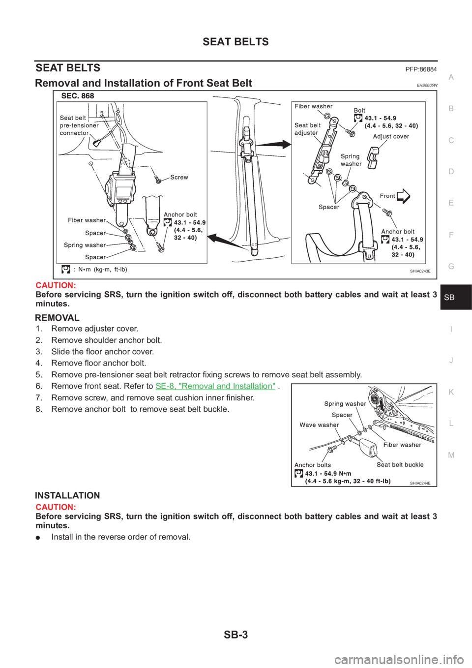
Removal and Installation of Front Seat BeltEHS0005W
CAUTION:
Before servicing SRS, turn the ignition switch off, disconnect both battery cables and wait at least 3
minutes.
REMOVAL
1. Remove adjuster cover.
2. Remove shoulder anchor bolt.
3. Slide the floor anchor cover.
4. Remove floor anchor bolt.
5. Remove pre-tensioner seat belt retractor fixing screws to remove seat belt assembly.
6. Remove front seat. Refer to SE-8, "
Removal and Installation" .
7. Remove screw, and remove seat cushion inner finisher.
8. Remove anchor bolt to remove seat belt buckle.
INSTALLATION
CAUTION:
Before servicing SRS, turn the ignition switch off, disconnect both battery cables and wait at least 3
minutes.
●Install in the reverse order of removal.
SHIA0243E
SHIA0244E
Page 2993 of 3833
![NISSAN X-TRAIL 2001 Service Repair Manual SEAT BELT WARNING SYSTEM
SB-11
C
D
E
F
G
I
J
K
L
MA
B
SB
Seat Belt Warning Lamp Inspection (Driver side)EHS000GT
1.FUSE INSPECTION
Check if 10A fuse [No.11, located in fuse block (J/B)] is blown.
OK o NISSAN X-TRAIL 2001 Service Repair Manual SEAT BELT WARNING SYSTEM
SB-11
C
D
E
F
G
I
J
K
L
MA
B
SB
Seat Belt Warning Lamp Inspection (Driver side)EHS000GT
1.FUSE INSPECTION
Check if 10A fuse [No.11, located in fuse block (J/B)] is blown.
OK o](/manual-img/5/57405/w960_57405-2992.png)
SEAT BELT WARNING SYSTEM
SB-11
C
D
E
F
G
I
J
K
L
MA
B
SB
Seat Belt Warning Lamp Inspection (Driver side)EHS000GT
1.FUSE INSPECTION
Check if 10A fuse [No.11, located in fuse block (J/B)] is blown.
OK or NG
OK >> GO TO 2.
NG >> Replace the 10A fuse [No.11, located in fuse block (J/B)].
2.POWER SUPPLY CIRCUIT
1. Disconnect combination meter harness connector.
2. Turn ignition switch “ON”.
3. Check voltage between combination meter harness connector
M46 terminal 46 (LHD models: W/L) or 59 (RHD models: W/L)
and ground.
OK or NG
OK >> GO TO3.
NG >> Repair or replace harness.
3.CHECK SEAT BELT BUCKLE SWITCH GROUND CIRCUIT
1. Connect combination meter.
2. Check continuity between combination meter harness connector
M46 terminal 46 (W/L) and 59 (W/B) (LHD models) or 59 (W/L)
and 48 (W/B) (RHD models)
OK or NG
OK >> GO TO 4.
NG >> Replace combination meter.Battery voltage should exist.
SHIA0303E
Continuity should exist.
PIIA4668E
Page 2994 of 3833

SB-12
SEAT BELT WARNING SYSTEM
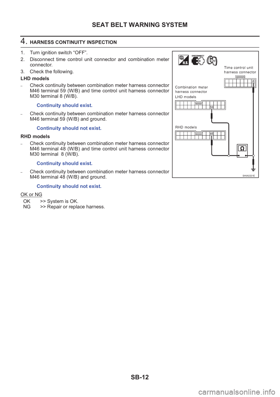
4. HARNESS CONTINUITY INSPECTION
1. Turn ignition switch “OFF”.
2. Disconnect time control unit connector and combination meter
connector.
3. Check the following.
LHD models
–Check continuity between combination meter harness connector
M46 terminal 59 (W/B) and time control unit harness connector
M30 terminal 8 (W/B).
–Check continuity between combination meter harness connector
M46 terminal 59 (W/B) and ground.
RHD models
–Check continuity between combination meter harness connector
M46 terminal 48 (W/B) and time control unit harness connector
M30 terminal 8 (W/B).
–Check continuity between combination meter harness connector
M46 terminal 48 (W/B) and ground.
OK or NG
OK >> System is OK.
NG >> Repair or replace harness.Continuity should exist.
Continuity should not exist.
Continuity should exist.
Continuity should not exist.
SHIA0331E