2001 NISSAN X-TRAIL check engine
[x] Cancel search: check enginePage 2917 of 3833
STEERING WHEEL
PS-7
C
D
E
F
H
I
J
K
L
MA
B
PS
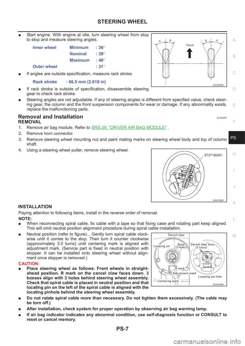
●Start engine. With engine at idle, turn steering wheel from stop
to stop and measure steering angles.
●If angles are outside specification, measure rack stroke.
●If rack stroke is outside of specification, disassemble steering
gear to check rack stroke.
●Steering angles are not adjustable. If any of steering angles is different from specified value, check steer-
ing gear, the column and the front suspension components for wear or damage. If any abnormality exists,
replace the malfunctioning parts.
Removal and InstallationEGS0004F
REMOVAL
1. Remove air bag module. Refer to SRS-29, "DRIVER AIR BAG MODULE" .
2. Remove horn connector.
3. Remove steering wheel mounting nut and paint mating marks on steering wheel body and top of column
shaft.
4. Using a steering wheel puller, remove steering wheel.
INSTALLATION
Paying attention to following items, install in the reverse order of removal.
NOTE:
●When reconnecting spiral cable, fix cable with a tape so that fixing case and rotating part keep aligned.
This will omit neutral position alignment procedure during spiral cable installation.
●Neutral position (refer to figure)... Gently turn spiral cable clock-
wise until it comes to the stop. Then turn it counter clockwise
(approximately 3.0 turns) until centering mark is aligned with
adjustment mark. (Service part is fixed in neutral position with
stopper. It can be installed onto steering wheel without align-
ment once stopper is removed.)
CAUTION:
●Place steering wheel as follows: Front wheels in straight-
ahead position. R mark on the cancel claw faces down. 3
bosses align with 3 holes behind steering wheel assembly.
Check that spiral cable is placed in neutral position and that
locating pin on the left of the spiral cable is aligned with the
locating pinhole behind the steering wheel assembly.
●Do not rotate spiral cable more than necessary. Do not tighten them excessively. (The cable may
be torn off.)
●After installation, check system for proper operation by observing air bag warning lamp.
●If air bag indicator indicates any abnormal condition, use self-diagnosis function or CONSULT to
reset or cancel memory.Inner wheel Minimum : 36°
Nominal : 39°
Maximum : 40°
Outer wheel : 31°
Rack stroke : 66.5 mm (2.618 in)
SGIA0055E
SGIA0080E
SGIA0096E
Page 2934 of 3833
PS-24
POWER STEERING OIL PUMP
POWER STEERING OIL PUMP
PFP:49110
On-Vehicle Inspection and ServiceEGS000AF
OIL PUMP PULLEY HYDRAULIC PRESSURE INSPECTION
Before starting following procedure, check tension of belt.
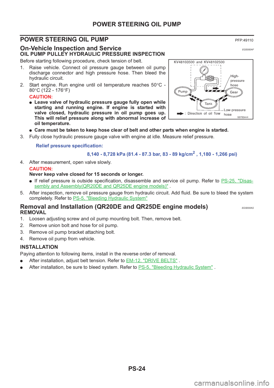
1. Raise vehicle. Connect oil pressure gauge between oil pump
discharge connector and high pressure hose. Then bleed the
hydraulic circuit.
2. Start engine. Run engine until oil temperature reaches 50°C -
80°C (122 - 176°F)
CAUTION:
●Leave valve of hydraulic pressure gauge fully open while
starting and running engine. If engine is started with
valve closed, hydraulic pressure in oil pump goes up.
This will relief pressure along with abnormal increase of
oil temperature.
●Care must be taken to keep hose clear of belt and other parts when engine is started.
3. Fully close hydraulic pressure gauge valve with engine at idle. Measure relief pressure.
4. After measurement, open valve slowly.
CAUTION:
Never keep valve closed for 15 seconds or longer.
●If relief pressure is outside specification, disassemble and service oil pump. Refer to PS-25, "Disas-
sembly and Assembly(QR20DE and QR25DE engine models)" .
5. After inspection, remove oil pressure gauge from hydraulic circuit. Add fluid. Be sure to bleed the system
completely. Refer to PS-5, "
Bleeding Hydraulic System"
Removal and Installation (QR20DE and QR25DE engine models)EGS000AG
REMOVAL
1. Loosen adjusting screw and oil pump mounting bolt. Then, remove belt.
2. Remove union bolt and hose for oil pump.
3. Remove oil pump bracket attaching bolt.
4. Remove oil pump from vehicle.
INSTALLATION
Paying attention to following items, install in the reverse order of removal.
●After installation, adjust belt tension. Refer to EM-12, "DRIVE BELTS" .
●After installation, be sure to bleed system. Refer to PS-5, "Bleeding Hydraulic System" . Relief pressure specification:
8,140 - 8,728 kPa (81.4 - 87.3 bar, 83 - 89 kg/cm
2 , 1,180 - 1,266 psi)
SST834-H
Page 2950 of 3833
FAX-2
PRECAUTIONS
PRECAUTIONS
PFP:00001
CautionEDS0005P
●When installing rubber parts, final tightening must be carried out under unladen condition* with tires on
ground.
●Oil will shorten the life of rubber bushes. Be sure to wipe off any spilled oil.
*: Fuel, radiator coolant and engine oil full. Spare tire, jack, hand tools and mats in designated positions.
●After installing removed suspension parts, check wheel alignment and adjust if necessary.
Observe the following precautions when disassembling and servicing drive shaft.
●Perform work in a location which is as dust-free and dirt-free as possible.
●Before disassembling and servicing, clean the outside of parts.
●Disassembly and service location must be taken to prevent the entry of foreign objects.
●Disassembled parts must be carefully reassembled in the correct order. If work is interrupted, a clean
cover must be placed over parts.
●Paper shop cloths must be used. Fabric shop cloths must not be used because of the danger of lint adher-
ing to parts.
●Disassembled parts (except for rubber parts) should be cleaned with kerosene which shall be removed by
blowing with air or wiping with paper shop cloths.
Page 2960 of 3833
FAX-12
FRONT DRIVE SHAFT
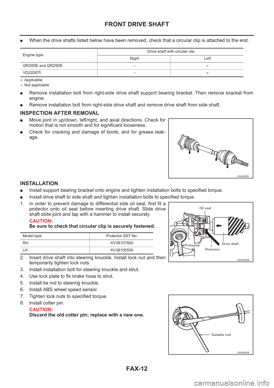
●When the drive shafts listed below have been removed, check that a circular clip is attached to the end.
×: Applicable
–: Not applicable
●Remove installation bolt from right-side drive shaft support bearing bracket. Then remove bracket from
engine.
●Remove installation bolt from right-side drive shaft and remove drive shaft from side shaft.
INSPECTION AFTER REMOVAL
●Move joint in up/down, left/right, and axial directions. Check for
motion that is not smooth and for significant looseness.
●Check for cracking and damage of boots, and for grease leak-
age.
INSTALLATION
●Install support bearing bracket onto engine and tighten installation bolts to specified torque.
●Install drive shaft to side shaft and tighten installation bolts to specified torque.
1. In order to prevent damage to differential side oil seal, first fit a
protector onto oil seal before inserting drive shaft. Slide drive
shaft slide joint and tap with a hammer to install securely.
CAUTION:
Be sure to check that circular clip is securely fastened.
2. Insert drive shaft into steering knuckle. Install lock nut and then
temporarily tighten lock nuts.
3. Install installation bolt for steering knuckle and strut.
4. Use lock plate to fix brake hose to strut.
5. Install tie rod to steering knuckle.
6. Install ABS wheel speed sensor.
7. Tighten lock nuts to specified torque.
8. Install cotter pin.
CAUTION:
Discard the old cotter pin; replace with a new one.
Engine typeDrive shaft with circular clip
Right Left
QR20DE and QR25DE –×
YD22DDTi –×
RAA0030D
Model type Protector SST No.
RH KV38107800
LH KV38105500
SDIA0593E
SDIA0603E
Page 2968 of 3833
RAX-2
PRECAUTIONS
PRECAUTIONS
PFP:00001
CautionEDS00060
●When installing rubber parts, final tightening must be carried out under unladen condition* with tires on
ground.
*: Fuel, radiator coolant and engine oil full. Spare tire, jack, hand tools and mats in designated positions.
●After installing removed suspension parts, check wheel alignment and adjust if necessary.
Observe the following precautions when disassembling and servicing drive shaft.
●Perform work in a location which is as dust-free and dirt-free as possible.
●Before disassembling and servicing, clean the outside of parts.
●The disassembly and service location must be clean. Care must be taken to prevent parts from becoming
dirty and to prevent the entry of foreign objects.
●Disassembled parts must be carefully reassembled in the correct order. If work is interrupted, a clean
cover must be placed over parts.
●Paper shop cloths must be used. Fabric shop cloths must not be used because of the danger of lint adher-
ing to parts.
●Disassembled parts (except for rubber parts) should be cleaned with kerosene which shall be removed by
blowing with air or wiping with paper shop cloths.
Page 3000 of 3833
SB-18
SEAT BELT WARNING SYSTEM
Vehicle Speed Signal Inspection
EHS000GZ
1. COMBINATION METER CHECK
Check the speed meter in combination meter operates normally.
OK or NG
OK >> GO TO 2.
NG >> Check combination meter system. Refer to DI-12, "
SYMPTOM CHART" (LHD models) or DI-32,
"SYMPTOM CHART" (RHD models).
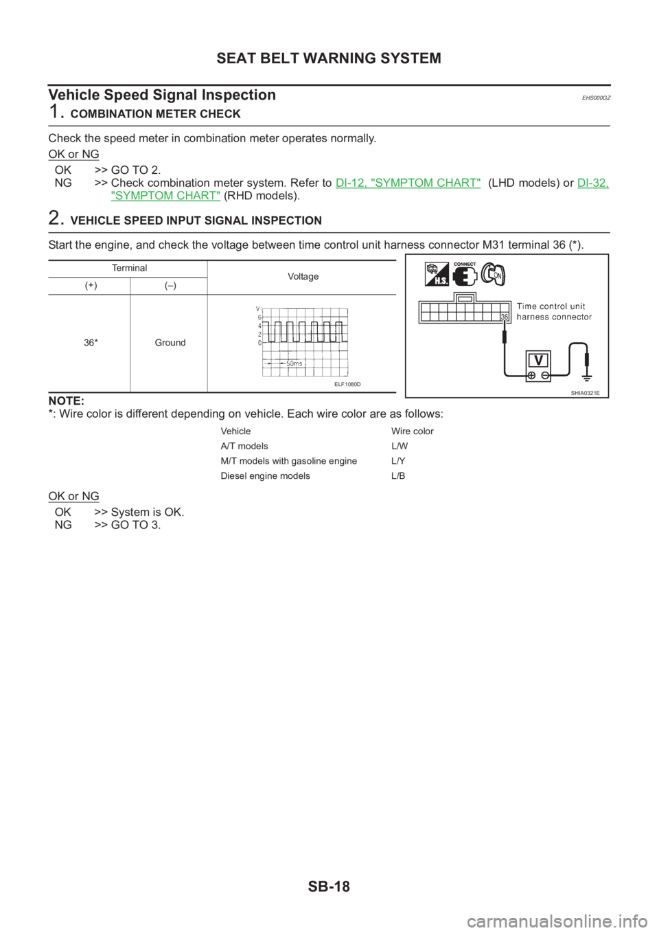
2. VEHICLE SPEED INPUT SIGNAL INSPECTION
Start the engine, and check the voltage between time control unit harness connector M31 terminal 36 (*).
NOTE:
*: Wire color is different depending on vehicle. Each wire color are as follows:
OK or NG
OK >> System is OK.
NG >> GO TO 3.
Terminal
Vo l ta g e
(+) (–)
36* Ground
Vehicle Wire color
A/T models L/W
M/T models with gasoline engine L/Y
Diesel engine models L/B
SHIA0321EELF1080D
Page 3001 of 3833
SEAT BELT WARNING SYSTEM
SB-19
C
D
E
F
G
I
J
K
L
MA
B
SB
3.HARNESS CONTINUITY INSPECTION
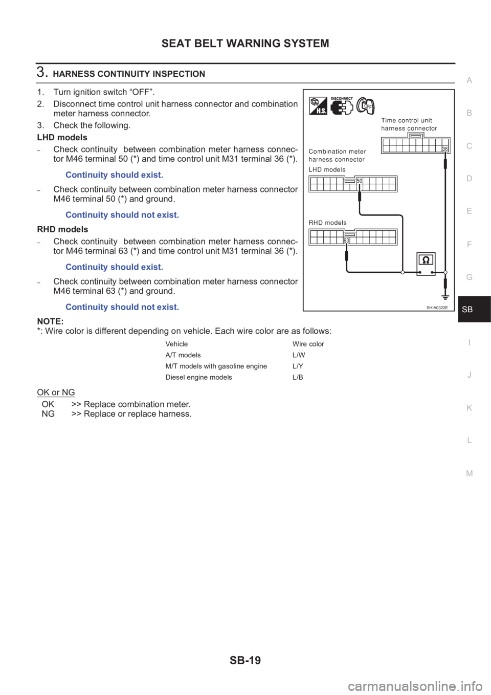
1. Turn ignition switch “OFF”.
2. Disconnect time control unit harness connector and combination
meter harness connector.
3. Check the following.
LHD models
–Check continuity between combination meter harness connec-
tor M46 terminal 50 (*) and time control unit M31 terminal 36 (*).
–Check continuity between combination meter harness connector
M46 terminal 50 (*) and ground.
RHD models
–Check continuity between combination meter harness connec-
tor M46 terminal 63 (*) and time control unit M31 terminal 36 (*).
–Check continuity between combination meter harness connector
M46 terminal 63 (*) and ground.
NOTE:
*: Wire color is different depending on vehicle. Each wire color are as follows:
OK or NG
OK >> Replace combination meter.
NG >> Replace or replace harness.Continuity should exist.
Continuity should not exist.
Continuity should exist.
Continuity should not exist.
Vehicle Wire color
A/T models L/W
M/T models with gasoline engine L/Y
Diesel engine models L/B
SHIA0322E
Page 3054 of 3833
BL-2
Power Supply and Ground Circuit Check ............... 60
Time Control Unit Lock Signal Circuit Check .......... 61
Time Control Unit Unlock Signal Circuit Check ...... 62
Hazard Reminder Check ........................................ 62
ID Code Entry Procedure ....................................... 63
Remote Controller Battery Replacement ................ 64
FRONT DOOR LOCK ............................................... 65
Component Parts Location ..................................... 65
Inspection and Adjustment ..................................... 65
OUT SIDE HANDLE ROD ADJUSTMENT .......... 65
Removal and Installation ........................................ 65
REMOVAL ........................................................... 65
INSTALLATION .................................................... 66
Disassembly and Assembly .................................... 67
DISASSEMBLY ................................................... 67
ASSEMBLY ......................................................... 67
REAR DOOR LOCK .................................................. 68
Component Parts Location ..................................... 68
Inspection and Adjustment ..................................... 68
OUT SIDE HANDLE ROD ADJUSTMENT .......... 68
Removal and Installation ........................................ 68
REMOVAL ........................................................... 68
INSTALLATION .................................................... 69
Disassembly and Assembly .................................... 70
DISASSEMBLY ................................................... 70
ASSEMBLY ......................................................... 70
BACK DOOR ............................................................. 71
Fitting Adjustment ................................................... 71
VERTICAL/LATERAL CLEARANCE ADJUST-
MENT .................................................................. 71
Back Door Assembly .............................................. 72
REMOVAL AND INSTALLATION ......................... 72
INSPECTION ....................................................... 72
Removal and Installation of Back Door Handle ...... 72
Removal and Installation of Back Door Lock and Actuator ................................................................... 73
Removal and Installation of Back Door Weatherstrip ... 73
FUEL FILLER LID OPENER ..................................... 75
Component Parts Location ..................................... 75
THEFT WARNING SYSTEM ..................................... 76
Wiring Diagram — THEFT —/PRI-WIRE ................ 76
LHD MODELS ...................................................... 76
RHD MODELS ..................................................... 78
NATS (NISSAN ANTI-THEFT SYSTEM) ................... 80
Component Parts and Harness Connector Location ... 80
System Description ................................................. 81
System Composition ............................................... 82
Wiring Diagram — NATS — .................................... 83
GASOLINE ENGINE MODELS ............................ 83
DIESEL ENGINE MODELS ................................. 84
CONSULT-II ............................................................ 85
CONSULT-II INSPECTION PROCEDURE .......... 85
CONSULT-II DIAGNOSTIC TEST MODE FUNC-
TION .................................................................... 85
HOW TO READ SELF-DIAGNOSTIC RESULTS ... 86
NATS SELF-DIAGNOSTIC RESULTS ITEM
CHART ................................................................. 86
Work Flow ............................................................... 88
Trouble Diagnoses .................................................. 89
SYMPTOM MATRIX CHART 1 ............................ 89
SYMPTOM MATRIX CHART 2 ............................ 90
DIAGNOSTIC SYSTEM DIAGRAM ..................... 90
Diagnostic Procedure 1 ........................................... 91
Diagnostic Procedure 2 ........................................... 91
Diagnostic Procedure 3 ........................................... 94
Diagnostic Procedure 4 ........................................... 95
Diagnostic Procedure 5 ........................................... 96
Diagnostic Procedure 6 ........................................... 97
Diagnostic Procedure 7 ........................................... 98
Diagnostic Procedure 8 ........................................... 99
How to Replace NATS IMMU ................................100