2001 NISSAN X-TRAIL check engine
[x] Cancel search: check enginePage 3150 of 3833
BL-98
NATS (NISSAN ANTI-THEFT SYSTEM)
5. CHECK IMMU FUNCTION
1. Connect IMMU connector.
2. Disconnect security indicator lamp connector.
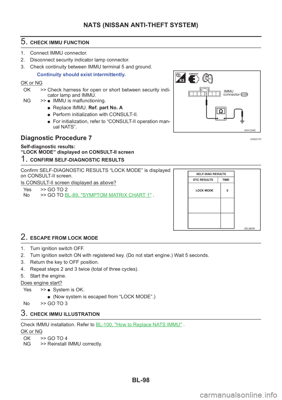
3. Check continuity between IMMU terminal 5 and ground.
OK or NG
OK >> Check harness for open or short between security indi-
cator lamp and IMMU.
NG >>
●IMMU is malfunctioning.
●Replace IMMU. Ref. part No. A
●Perform initialization with CONSULT-II.
●For initialization, refer to “CONSULT-II operation man-
ual NATS”.
Diagnostic Procedure 7EIS001TD
Self-diagnostic results:
“LOCK MODE” displayed on CONSULT-II screen
1. CONFIRM SELF-DIAGNOSTIC RESULTS
Confirm SELF-DIAGNOSTIC RESULTS “LOCK MODE” is displayed
on CONSULT-II screen.
Is CONSULT-II screen displayed as above?
Yes >> GO TO 2
No >> GO TO BL-89, "
SYMPTOM MATRIX CHART 1" .
2. ESCAPE FROM LOCK MODE
1. Turn ignition switch OFF.
2. Turn ignition switch ON with registered key. (Do not start engine.) Wait 5 seconds.
3. Return the key to OFF position.
4. Repeat steps 2 and 3 twice (total of three cycles).
5. Start the engine.
Does engine start?
Ye s > >●System is OK.
●(Now system is escaped from “LOCK MODE”.)
No >> GO TO 3
3. CHECK IMMU ILLUSTRATION
Check IMMU installation. Refer to BL-100, "
How to Replace NATS IMMU" .
OK or NG
OK >> GO TO 4
NG >> Reinstall IMMU correctly.Continuity should exist intermittently.
SIIA1244E
SEL960W
Page 3278 of 3833
ATC-2
DEFROSTER (DEF) SWITCH ............................. 30
MODE SWITCH ................................................... 30
FAN SWITCH ...................................................... 30
OFF SWITCH ...................................................... 30
FRESH (FRE) SWITCH ....................................... 30
RECIRCULATION (REC) SWITCH ..................... 30
Discharge Air Flow ................................................. 31
System Description ................................................. 32
SWITCHES AND THEIR CONTROL FUNCTION ... 32
TROUBLE DIAGNOSIS ............................................ 33
How to Perform Trouble Diagnoses for Quick and
Accurate Repair ...................................................... 33
WORK FLOW ...................................................... 33
SYMPTOM TABLE .............................................. 33
Component Parts and Harness Connector Location ... 34
ENGINE COMPARTMENT .................................. 34
PASSENGER COMPARTMENT .......................... 35
Circuit Diagram ....................................................... 36
WITH GASOLINE ENGINE ................................. 36
WITH DIESEL ENGINE ....................................... 37
Wiring Diagram ....................................................... 38
WITH GASOLINE ENGINE ................................. 38
WITH DIESEL ENGINE ....................................... 41
Auto Amp. Terminals and Reference Value ............ 44
PIN CONNECTOR TERMINAL LAYOUT ............ 44
AUTO AMP. INSPECTION TABLE ...................... 44
Self-diagnosis Function .......................................... 46
DESCRIPTION .................................................... 46
PROCEDURE ...................................................... 47
AUXILIARY MECHANISM: TEMPERATURE
SETTING TRIMMER ........................................... 52
AUXILIARY MECHANISM: FOOT POSITION
SETTING TRIMMER ........................................... 53
AUXILIARY MECHANISM: INLET PORT MEM-
ORY FUNCTION (FOR LHD MODELS) .............. 54
Operational Check .................................................. 54
CHECKING MEMORY FUNCTION ..................... 54
CHECKING BLOWER ......................................... 55
CHECKING DISCHARGE AIR ............................ 55
CHECKING RECIRCULATION ............................ 55
CHECKING TEMPERATURE DECREASE ......... 56
CHECKING TEMPERATURE INCREASE .......... 56
CHECKING AUTO MODE ................................... 56
Power Supply and Ground Circuit for Auto Amp. ... 57
INSPECTION FLOW ........................................... 57
COMPONENT DESCRIPTION ............................ 57
DIAGNOSTIC PROCEDURE .............................. 58
LAN System Circuit ............................................. ... 59
DIAGNOSTIC PROCEDURE .............................. 59
Mode Door Motor Circuit ........................................ 62
INSPECTION FLOW ........................................
... 62
SYSTEM DESCRIPTION .................................... 63
COMPONENT DESCRIPTION ............................ 64
DIAGNOSTIC PROCEDURE .............................. 64
Air Mix Door Motor Circuit ...................................... 64
INSPECTION FLOW ........................................... 65
SYSTEM DESCRIPTION .................................... 66
COMPONENT DESCRIPTION ............................ 66
DIAGNOSTIC PROCEDURE .............................. 67Intake Door Motor Circuit ........................................ 68
INSPECTION FLOW ............................................ 68
SYSTEM DESCRIPTION ..................................... 69
COMPONENT DESCRIPTION ............................ 69
DIAGNOSTIC PROCEDURE ............................... 70
Blower Motor Circuit ................................................ 70
INSPECTION FLOW ............................................ 71
SYSTEM DESCRIPTION ..................................... 72
COMPONENT DESCRIPTION ............................ 74
DIAGNOSTIC PROCEDURE ............................... 74
COMPONENT INSPECTION ............................... 77
Magnet Clutch Circuit .............................................. 78
INSPECTION FLOW ............................................ 78
SYSTEM DESCRIPTION ..................................... 79
DIAGNOSTIC PROCEDURE ............................... 79
COMPONENT INSPECTION ............................... 84
Insufficient Cooling .................................................. 86
INSPECTION FLOW ............................................ 86
PERFORMANCE TEST DIAGNOSES ................ 88
PERFORMANCE CHART .................................... 90
TROUBLE DIAGNOSES FOR UNUSUAL PRES-
SURE ................................................................... 92
Insufficient Heating ................................................. 95
INSPECTION FLOW ............................................ 95
Noise ....................................................................... 97
INSPECTION FLOW ............................................ 97
Self-diagnosis ......................................................... 98
INSPECTION FLOW ............................................ 98
Memory Function .................................................... 99
INSPECTION FLOW ............................................ 99
Ambient Sensor Circuit .........................................100
COMPONENT DESCRIPTION ..........................100
AMBIENT TEMPERATURE INPUT PROCESS .100
DIAGNOSTIC PROCEDURE .............................100
COMPONENT INSPECTION .............................102
In-vehicle Sensor Circuit .......................................102
COMPONENT DESCRIPTION ..........................102
DIAGNOSTIC PROCEDURE .............................103
COMPONENT INSPECTION .............................104
Sunload Sensor Circuit .........................................105
COMPONENT DESCRIPTION ..........................105
SUNLOAD INPUT PROCESS ...........................105
DIAGNOSTIC PROCEDURE .............................105
COMPONENT INSPECTION .............................107
Intake Sensor Circuit .............................................108
COMPONENT DESCRIPTION ..........................108
DIAGNOSTIC PROCEDURE .............................108
CONTROLLER ........................................................ 111
Removal and Installation .......................................111
Disassembly and Assembly ..................................111
AMBIENT SENSOR ................................................112
Removal and Installation .......................................112
IN-VEHICLE SENSOR ............................................113
Removal and Installation .......................................113
SUNLOAD SENSOR ...............................................114
Removal and Installation .......................................114
INTAKE SENSOR CIRCUIT ....................................115
Removal and Installation .......................................115
BLOWER UNIT ........................................................116
Page 3279 of 3833
ATC-3
C
D
E
F
G
H
I
K
L
MA
B
AT C Removal and Installation ....................................... 116
REMOVAL .......................................................... 116
INSTALLATION .................................................. 116
Disassembly and Assembly .................................. 117
BLOWER MOTOR ...................................................118
Removal and Installation ....................................... 118
INTAKE DOOR MOTOR ..........................................119
Removal and Installation ....................................... 119
FAN CONTROL AMPLIFIER .................................. 120
Removal and Installation ...................................... 120
VENTILATION AIR FILTER .................................... 121
Removal and Installation ...................................... 121
FUNCTION ........................................................ 121
REPLACEMENT TIMING .................................. 121
REPLACEMENT AND PROCEDURES ............ 121
CLEANING ....................................................... . 121
HEATER & COOLING UNIT ASSEMBLY .............. 122
Removal and Installation ...................................... 122
REMOVAL ......................................................... 122
INSTALLATION ................................................. 123
Disassembly and Assembly ................................. 123
MODE DOOR MOTOR ........................................... 124
Removal and Installation ...................................... 124
AIR MIX DOOR MOTOR ......................................... 125
Removal and Installation ...................................... 125
HEATER CORE ...................................................... 126
Removal and Installation ...................................... 126
DUCTS AND GRILLES .......................................... 127
Removal and Installation ...................................... 127
VENTILATOR DUCT, DEFROSTER NOZZLE
AND DEFROSTER DUCTS .............................. 127
CENTER VENTILATOR GRILLE ...................... 127
SIDE VENTILATOR GRILLE ............................. 127
FOOT DUCT ..................................................... 128
FLOOR DUCT ................................................... 128
REFRIGERANT LINES ........................................... 129
HFC-134a (R-134a) Service Procedure ............... 129
SETTING OF SERVICE TOOLS AND EQUIP-
MENT ................................................................ 129
Components ......................................................... 131
WITH GASOLINE ENGINE ............................... 131
WITH DIESEL ENGINE .................................... 132
Removal and Installation for Compressor ............ 132REMOVAL .........................................................132
INSTALLATION .................................................134
Removal and Installation for Compressor Clutch . 135
REMOVAL .........................................................135
INSTALLATION .................................................138
Removal and Installation for Low-pressure flexible
hose ......................................................................141
REMOVAL .........................................................141
INSTALLATION .................................................141
Removal and Installation for High-pressure flexible
hose ......................................................................142
REMOVAL .........................................................142
INSTALLATION .................................................142
Removal and Installation for High-pressure pipe ..142
REMOVAL .........................................................142
INSTALLATION .................................................142
Removal and Installation for Refrigerant Pressure
Sensor ..................................................................143
Removal and Installation for Dual-pressure Switch .143
Removal and Installation for Condenser ..............143
REMOVAL .........................................................143
INSTALLATION .................................................144
Removal and Installation for Evaporator ..............145
REMOVAL .........................................................145
INSTALLATION .................................................145
Removal and Installation for Expansion Valve ......146
Removal and Installation for Liquid Tank ..............146
REMOVAL .........................................................146
INSTALLATION .................................................146
Checking for Refrigerant Leaks ............................146
Checking System for Leaks Using the Fluorescent
Leak Detector .......................................................147
Dye Injection .........................................................147
Electronic Refrigerant Leak Detector ....................147
PRECAUTIONS FOR HANDLING LEAK
DETECTOR .......................................................147
CHECKING PROCEDURE ...............................148
SERVICE DATA AND SPECIFICATIONS (SDS) ....150
COMPRESSOR ....................................................150
LUBRICANT .........................................................150
REFRIGERANT ....................................................150
ENGINE IDLING SPEED ......................................150
BELT TENSION ................................................... .150
Page 3286 of 3833
ATC-10
PRECAUTIONS
●After compressor service operation, turn the compressor shaft by hand more than five turns in
both directions. This will equally distribute lubricant inside the compressor. After the compressor
is installed, let the engine idle and operate the compressor for one hour.
●After replacing the compressor magnet clutch, apply voltage to the new one and check for normal
operation.
Precautions for Service EquipmentEJS000T6
RECOVERY/RECYCLING EQUIPMENT
Be certain to follow the manufacturers instructions for machine operation and machine maintenance. Never
introduce any refrigerant other than that specified into the machine.
ELECTRONIC LEAK DETECTOR
Be certain to follow the manufacturer's instructions for tester operation and tester maintenance.
VACUUM PUMP
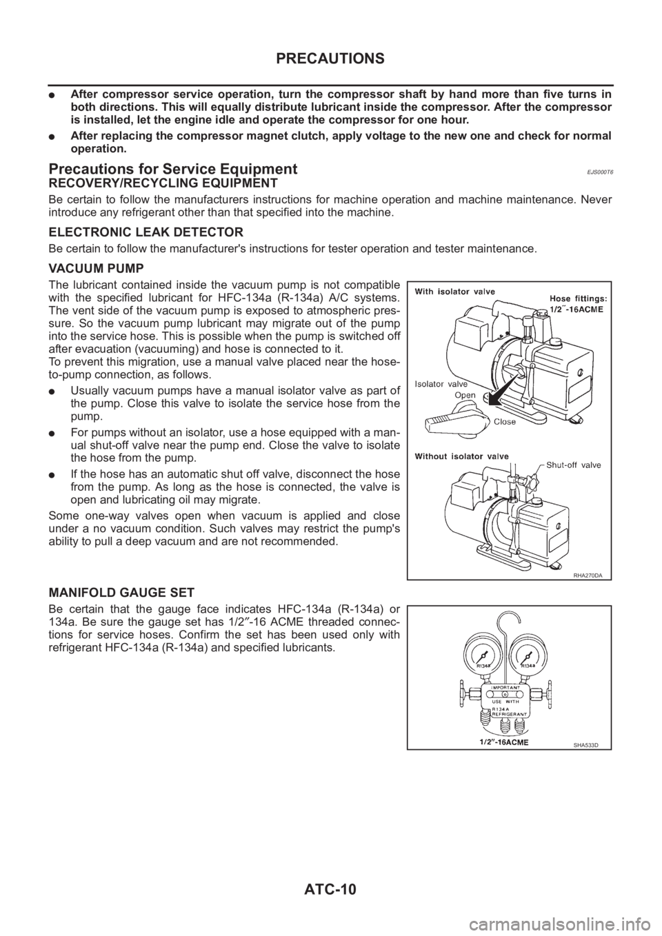
The lubricant contained inside the vacuum pump is not compatible
with the specified lubricant for HFC-134a (R-134a) A/C systems.
The vent side of the vacuum pump is exposed to atmospheric pres-
sure. So the vacuum pump lubricant may migrate out of the pump
into the service hose. This is possible when the pump is switched off
after evacuation (vacuuming) and hose is connected to it.
To prevent this migration, use a manual valve placed near the hose-
to-pump connection, as follows.
●Usually vacuum pumps have a manual isolator valve as part of
the pump. Close this valve to isolate the service hose from the
pump.
●For pumps without an isolator, use a hose equipped with a man-
ual shut-off valve near the pump end. Close the valve to isolate
the hose from the pump.
●If the hose has an automatic shut off valve, disconnect the hose
from the pump. As long as the hose is connected, the valve is
open and lubricating oil may migrate.
Some one-way valves open when vacuum is applied and close
under a no vacuum condition. Such valves may restrict the pump's
ability to pull a deep vacuum and are not recommended.
MANIFOLD GAUGE SET
Be certain that the gauge face indicates HFC-134a (R-134a) or
134a. Be sure the gauge set has 1/2″-16 ACME threaded connec-
tions for service hoses. Confirm the set has been used only with
refrigerant HFC-134a (R-134a) and specified lubricants.
RHA270DA
SHA533D
Page 3300 of 3833
ATC-24
LUBRICANT
LUBRICANT
PFP:KLG00
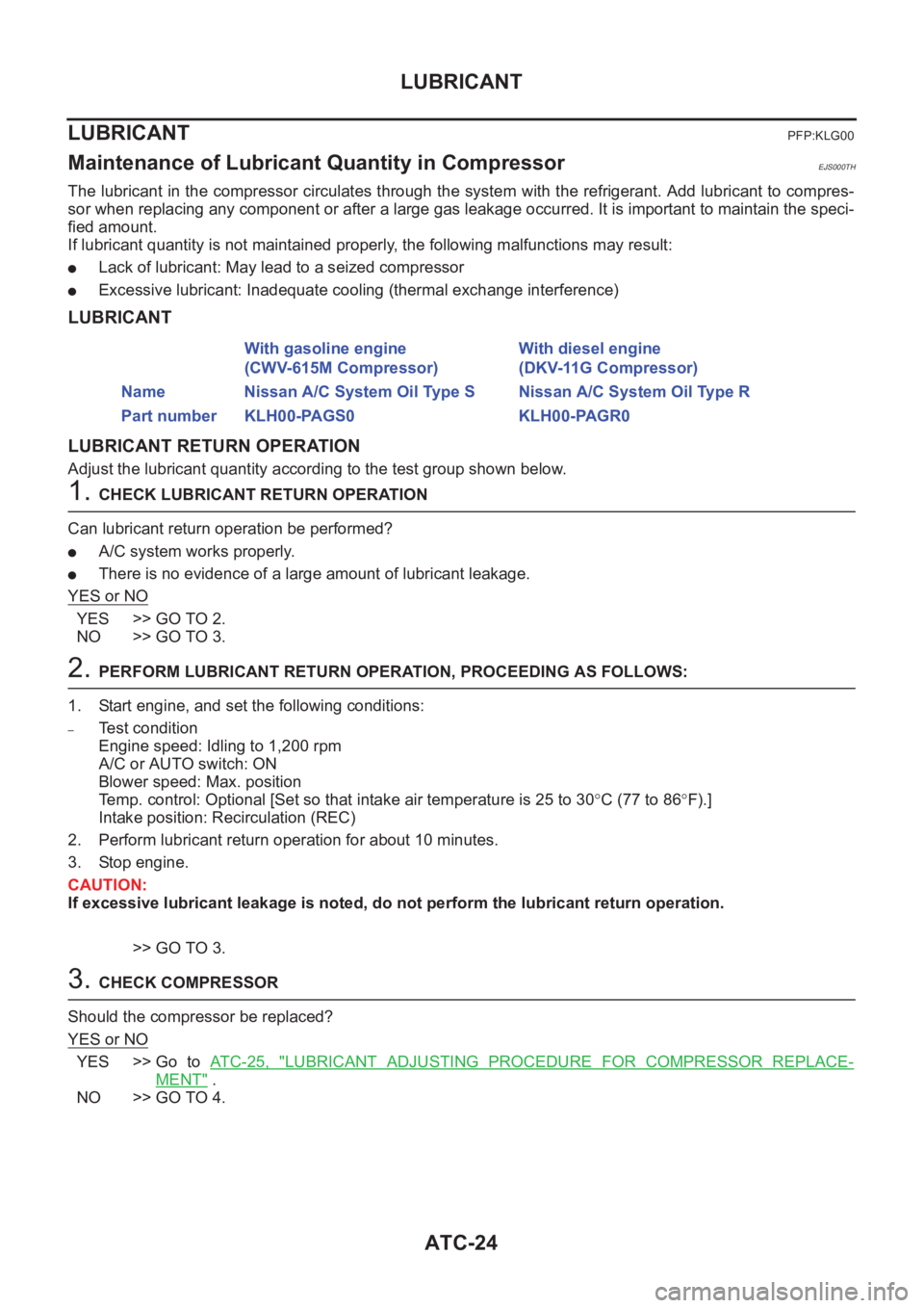
Maintenance of Lubricant Quantity in CompressorEJS000TH
The lubricant in the compressor circulates through the system with the refrigerant. Add lubricant to compres-
sor when replacing any component or after a large gas leakage occurred. It is important to maintain the speci-
fied amount.
If lubricant quantity is not maintained properly, the following malfunctions may result:
●Lack of lubricant: May lead to a seized compressor
●Excessive lubricant: Inadequate cooling (thermal exchange interference)
LUBRICANT
LUBRICANT RETURN OPERATION
Adjust the lubricant quantity according to the test group shown below.
1. CHECK LUBRICANT RETURN OPERATION
Can lubricant return operation be performed?
●A/C system works properly.
●There is no evidence of a large amount of lubricant leakage.
YES or NO
YES >> GO TO 2.
NO >> GO TO 3.
2. PERFORM LUBRICANT RETURN OPERATION, PROCEEDING AS FOLLOWS:
1. Start engine, and set the following conditions:
–Test condition
Engine speed: Idling to 1,200 rpm
A/C or AUTO switch: ON
Blower speed: Max. position
Temp. control: Optional [Set so that intake air temperature is 25 to 30°C (77 to 86°F).]
Intake position: Recirculation (REC)
2. Perform lubricant return operation for about 10 minutes.
3. Stop engine.
CAUTION:
If excessive lubricant leakage is noted, do not perform the lubricant return operation.
>> GO TO 3.
3. CHECK COMPRESSOR
Should the compressor be replaced?
YES or NO
YES >> Go to AT C - 2 5 , "LUBRICANT ADJUSTING PROCEDURE FOR COMPRESSOR REPLACE-
MENT" .
NO >> GO TO 4.With gasoline engine
(CWV-615M Compressor)With diesel engine
(DKV-11G Compressor)
Name Nissan A/C System Oil Type S Nissan A/C System Oil Type R
Part number KLH00-PAGS0 KLH00-PAGR0
Page 3323 of 3833
TROUBLE DIAGNOSIS
ATC-47
C
D
E
F
G
H
I
K
L
MA
B
AT C
PROCEDURE
1.SET IN SELF-DIAGNOSTIC MODE
1. Turn ignition switch ON.
2. Set in self-diagnostic mode as follows. Within 10 seconds after starting engine (ignition switch is turned
ON.), press OFF switch for at least 5 seconds.
>> GO TO 2.
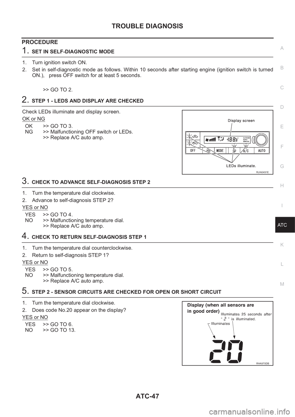
2.STEP 1 - LEDS AND DISPLAY ARE CHECKED
Check LEDs illuminate and display screen.
OK or NG
OK >> GO TO 3.
NG >> Malfunctioning OFF switch or LEDs.
>> Replace A/C auto amp.
3.CHECK TO ADVANCE SELF-DIAGNOSIS STEP 2
1. Turn the temperature dial clockwise.
2. Advance to self-diagnosis STEP 2?
YES or NO
YES >> GO TO 4.
NO >> Malfunctioning temperature dial.
>> Replace A/C auto amp.
4.CHECK TO RETURN SELF-DIAGNOSIS STEP 1
1. Turn the temperature dial counterclockwise.
2. Return to self-diagnosis STEP 1?
YES or NO
YES >> GO TO 5.
NO >> Malfunctioning temperature dial.
>> Replace A/C auto amp.
5.STEP 2 - SENSOR CIRCUITS ARE CHECKED FOR OPEN OR SHORT CIRCUIT
1. Turn the temperature dial clockwise.
2. Does code No.20 appear on the display?
YES or NO
YES >> GO TO 6.
NO >> GO TO 13.
RJIA0491E
RHA970DB
Page 3324 of 3833
ATC-48
TROUBLE DIAGNOSIS
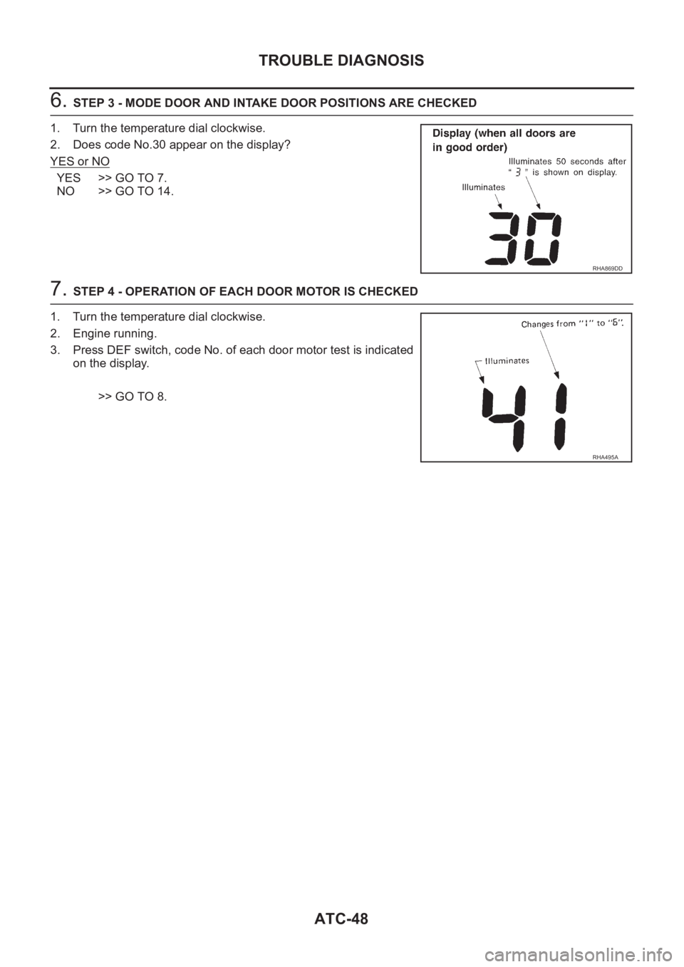
6. STEP 3 - MODE DOOR AND INTAKE DOOR POSITIONS ARE CHECKED
1. Turn the temperature dial clockwise.
2. Does code No.30 appear on the display?
YES or NO
YES >> GO TO 7.
NO >> GO TO 14.
7. STEP 4 - OPERATION OF EACH DOOR MOTOR IS CHECKED
1. Turn the temperature dial clockwise.
2. Engine running.
3. Press DEF switch, code No. of each door motor test is indicated
on the display.
>> GO TO 8.
RHA869DD
RHA495A
Page 3330 of 3833
ATC-54
TROUBLE DIAGNOSIS
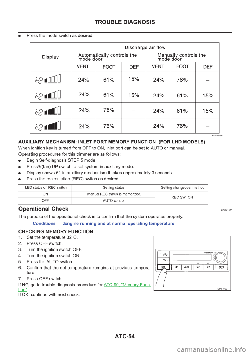
●Press the mode switch as desired.
AUXILIARY MECHANISM: INLET PORT MEMORY FUNCTION (FOR LHD MODELS)
When ignition key is turned from OFF to ON, inlet port can be set to AUTO or manual.
Operating procedures for this trimmer are as follows:
●Begin Self-diagnosis STEP 5 mode.
●Press (fan) UP switch to set system in auxiliary mode.
●Display shows 61 in auxiliary mechanism.It takes approximately 3 seconds.
●Press the recirculation (REC) switch as desired.
Operational CheckEJS001GY
The purpose of the operational check is to confirm that the system operates properly.
CHECKING MEMORY FUNCTION
1. Set the temperature 32°C.
2. Press OFF switch.
3. Turn the ignition switch OFF.
4. Turn the ignition switch ON.
5. Press the AUTO switch.
6. Confirm that the set temperature remains at previous tempera-
ture.
7. Press OFF switch.
If NG, go to trouble diagnosis procedure for AT C - 9 9 , "
Memory Func-
tion" .
If OK, continue with next check.
RJIA0040E
LED status of REC switch Setting status Setting changeover method
ON Manual REC status is memorized.
REC SW: ON
OFF AUTO control
Conditions :Engine running and at normal operating temperature
RJIA0496E