Page 3348 of 3833
ATC-72
TROUBLE DIAGNOSIS
SYSTEM DESCRIPTION
Component Parts
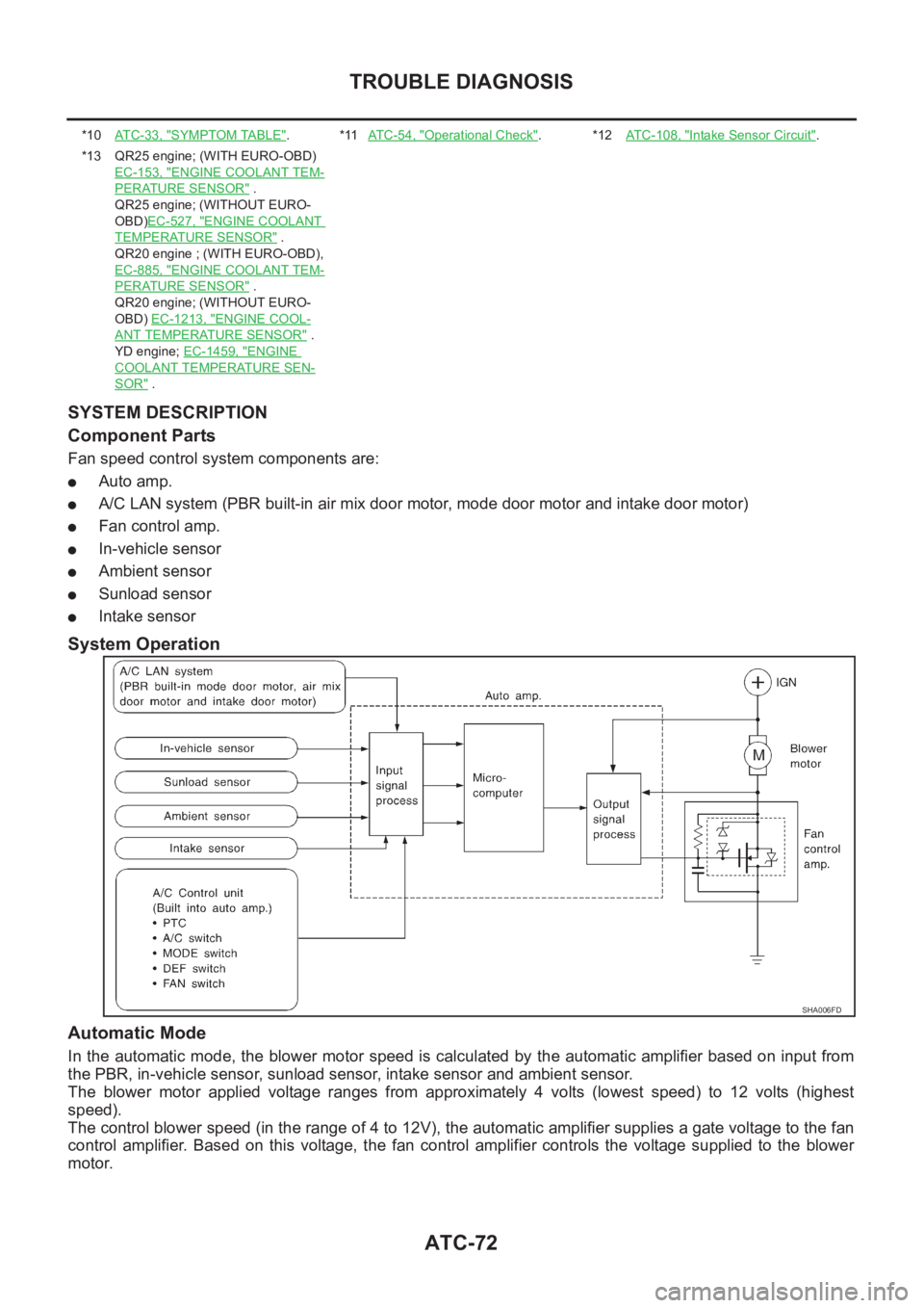
Fan speed control system components are:
●Auto amp.
●A/C LAN system (PBR built-in air mix door motor, mode door motor and intake door motor)
●Fan control amp.
●In-vehicle sensor
●Ambient sensor
●Sunload sensor
●Intake sensor
System Operation
Automatic Mode
In the automatic mode, the blower motor speed is calculated by the automatic amplifier based on input from
the PBR, in-vehicle sensor, sunload sensor, intake sensor and ambient sensor.
The blower motor applied voltage ranges from approximately 4 volts (lowest speed) to 12 volts (highest
speed).
The control blower speed (in the range of 4 to 12V), the automatic amplifier supplies a gate voltage to the fan
control amplifier. Based on this voltage, the fan control amplifier controls the voltage supplied to the blower
motor.
*10AT C - 3 3 , "SYMPTOM TABLE".*11AT C - 5 4 , "Operational Check".*12ATC-108, "Intake Sensor Circuit".
*13 QR25 engine; (WITH EURO-OBD)
EC-153, "
ENGINE COOLANT TEM-
PERATURE SENSOR" .
QR25 engine; (WITHOUT EURO-
OBD)EC-527, "
ENGINE COOLANT
TEMPERATURE SENSOR" .
QR20 engine ; (WITH EURO-OBD),
EC-885, "
ENGINE COOLANT TEM-
PERATURE SENSOR" .
QR20 engine; (WITHOUT EURO-
OBD) EC-1213, "
ENGINE COOL-
ANT TEMPERATURE SENSOR" .
YD engine; EC-1459, "
ENGINE
COOLANT TEMPERATURE SEN-
SOR" .
SHA006FD
Page 3357 of 3833
TROUBLE DIAGNOSIS
ATC-81
C
D
E
F
G
H
I
K
L
MA
B
AT C
4.CHECK A/C RELAY AFTER DISCONNECTING IT
Refer to ATC-84, "
A/C Relay" .
OK or NG
OK >> Reconnect A/C relay. And GO TO 5.
NG >> 1. replace A/C relay.
2. Go to self-diagnosis AT C - 4 7 , "
PROCEDURE" and perform self-diagnosis STEP-4.Confirm that
magnet clutch operation is normal.
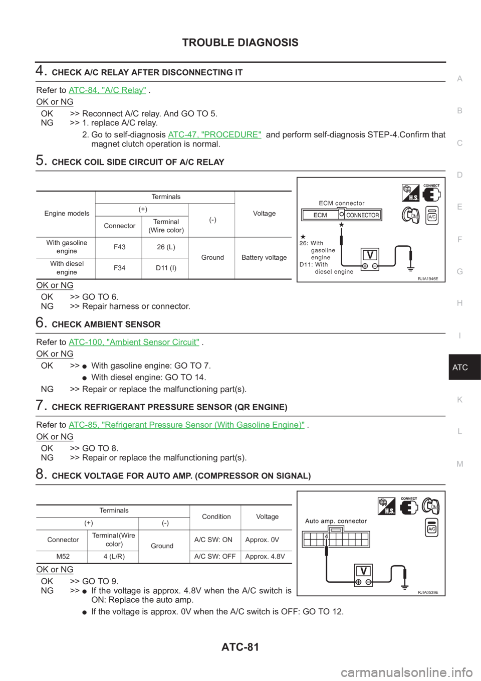
5.CHECK COIL SIDE CIRCUIT OF A/C RELAY
OK or NG
OK >> GO TO 6.
NG >> Repair harness or connector.
6.CHECK AMBIENT SENSOR
Refer to ATC-100, "
Ambient Sensor Circuit" .
OK or NG
OK >>●With gasoline engine: GO TO 7.
●With diesel engine: GO TO 14.
NG >> Repair or replace the malfunctioning part(s).
7.CHECK REFRIGERANT PRESSURE SENSOR (QR ENGINE)
Refer to ATC-85, "
Refrigerant Pressure Sensor (With Gasoline Engine)" .
OK or NG
OK >> GO TO 8.
NG >> Repair or replace the malfunctioning part(s).
8.CHECK VOLTAGE FOR AUTO AMP. (COMPRESSOR ON SIGNAL)
OK or NG
OK >> GO TO 9.
NG >>
●If the voltage is approx. 4.8V when the A/C switch is
ON: Replace the auto amp.
●If the voltage is approx. 0V when the A/C switch is OFF: GO TO 12.
Engine modelsTerminals
Voltag e (+)
(-)
ConnectorTerminal
(Wire color)
With gasoline
engineF43 26 (L)
Ground Battery voltage
With diesel
engineF34 D11 (I)
RJIA1946E
Terminals
Condition Voltage
(+) (-)
ConnectorTe r m i n a l ( W i r e
color)
GroundA/C SW: ON Approx. 0V
M52 4 (L/R) A/C SW: OFF Approx. 4.8V
RJIA0539E
Page 3359 of 3833
TROUBLE DIAGNOSIS
ATC-83
C
D
E
F
G
H
I
K
L
MA
B
AT C
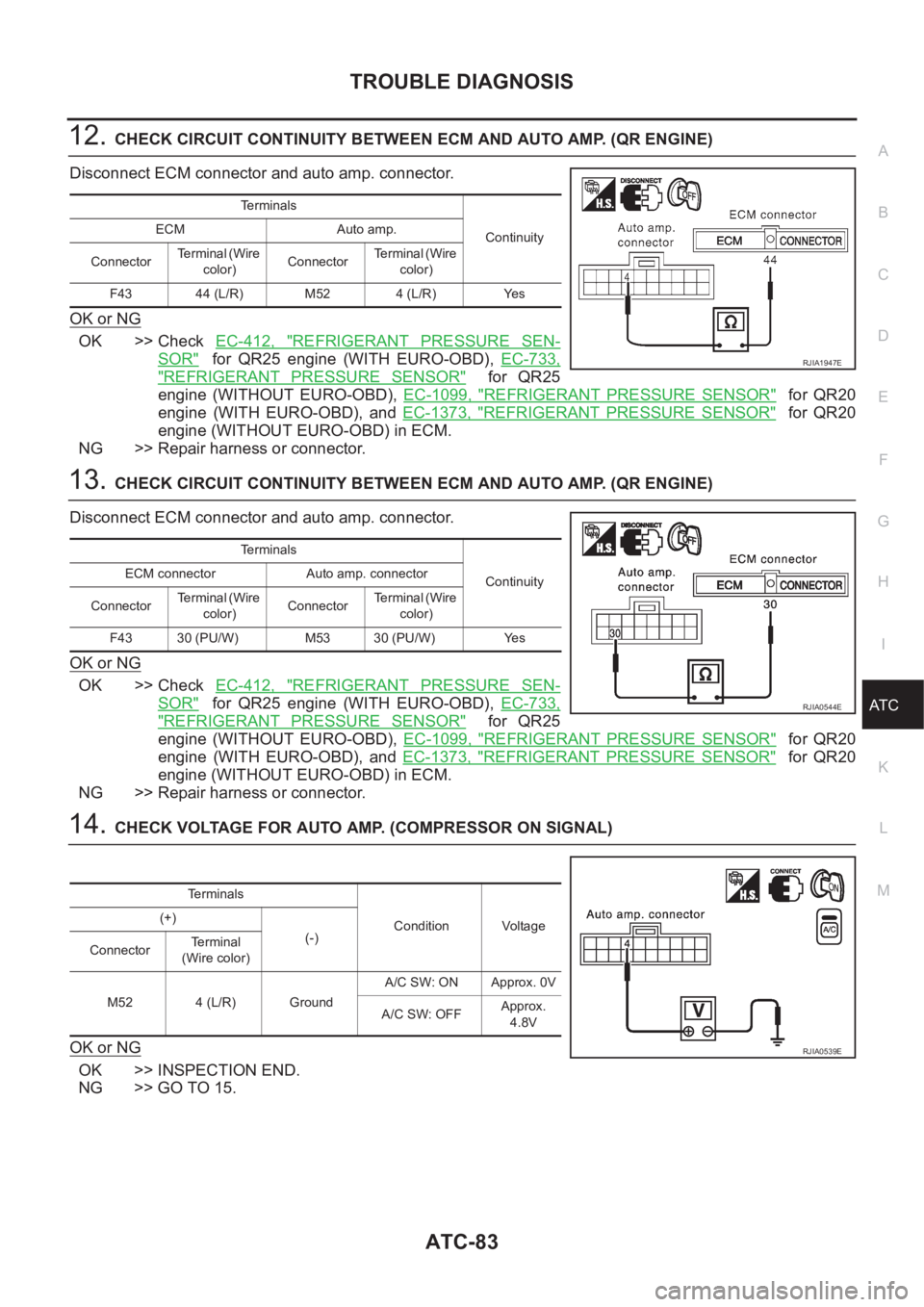
12.CHECK CIRCUIT CONTINUITY BETWEEN ECM AND AUTO AMP. (QR ENGINE)
Disconnect ECM connector and auto amp. connector.
OK or NG
OK >> Check EC-412, "REFRIGERANT PRESSURE SEN-
SOR" for QR25 engine (WITH EURO-OBD), EC-733,
"REFRIGERANT PRESSURE SENSOR" for QR25
engine (WITHOUT EURO-OBD), EC-1099, "
REFRIGERANT PRESSURE SENSOR" for QR20
engine (WITH EURO-OBD), and EC-1373, "
REFRIGERANT PRESSURE SENSOR" for QR20
engine (WITHOUT EURO-OBD) in ECM.
NG >> Repair harness or connector.
13.CHECK CIRCUIT CONTINUITY BETWEEN ECM AND AUTO AMP. (QR ENGINE)
Disconnect ECM connector and auto amp. connector.
OK or NG
OK >> Check EC-412, "REFRIGERANT PRESSURE SEN-
SOR" for QR25 engine (WITH EURO-OBD), EC-733,
"REFRIGERANT PRESSURE SENSOR" for QR25
engine (WITHOUT EURO-OBD), EC-1099, "
REFRIGERANT PRESSURE SENSOR" for QR20
engine (WITH EURO-OBD), and EC-1373, "
REFRIGERANT PRESSURE SENSOR" for QR20
engine (WITHOUT EURO-OBD) in ECM.
NG >> Repair harness or connector.
14.CHECK VOLTAGE FOR AUTO AMP. (COMPRESSOR ON SIGNAL)
OK or NG
OK >> INSPECTION END.
NG >> GO TO 15.
Te r m i n a l s
Continuity ECM Auto amp.
ConnectorTerminal (Wire
color)ConnectorTerminal (Wire
color)
F43 44 (L/R) M52 4 (L/R) Yes
RJIA1947E
Te r m i n a l s
Continuity ECM connector Auto amp. connector
ConnectorTerminal (Wire
color)ConnectorTerminal (Wire
color)
F43 30 (PU/W) M53 30 (PU/W) Yes
RJIA0544E
Terminals
Condition Voltage (+)
(-)
ConnectorTerminal
(Wire color)
M52 4 (L/R) GroundA/C SW: ON Approx. 0V
A/C SW: OFFApprox.
4.8V
RJIA0539E
Page 3360 of 3833
ATC-84
TROUBLE DIAGNOSIS
15. CHECK DUAL- PRESSURE SWITCH (YD ENGINE)
Refer to AT C - 8 5 , "
Dual-Pressure Switch (With Diesel Engine)" .
OK or NG
OK >> GO TO 16.
NG >> Replace the dual-pressure switch.
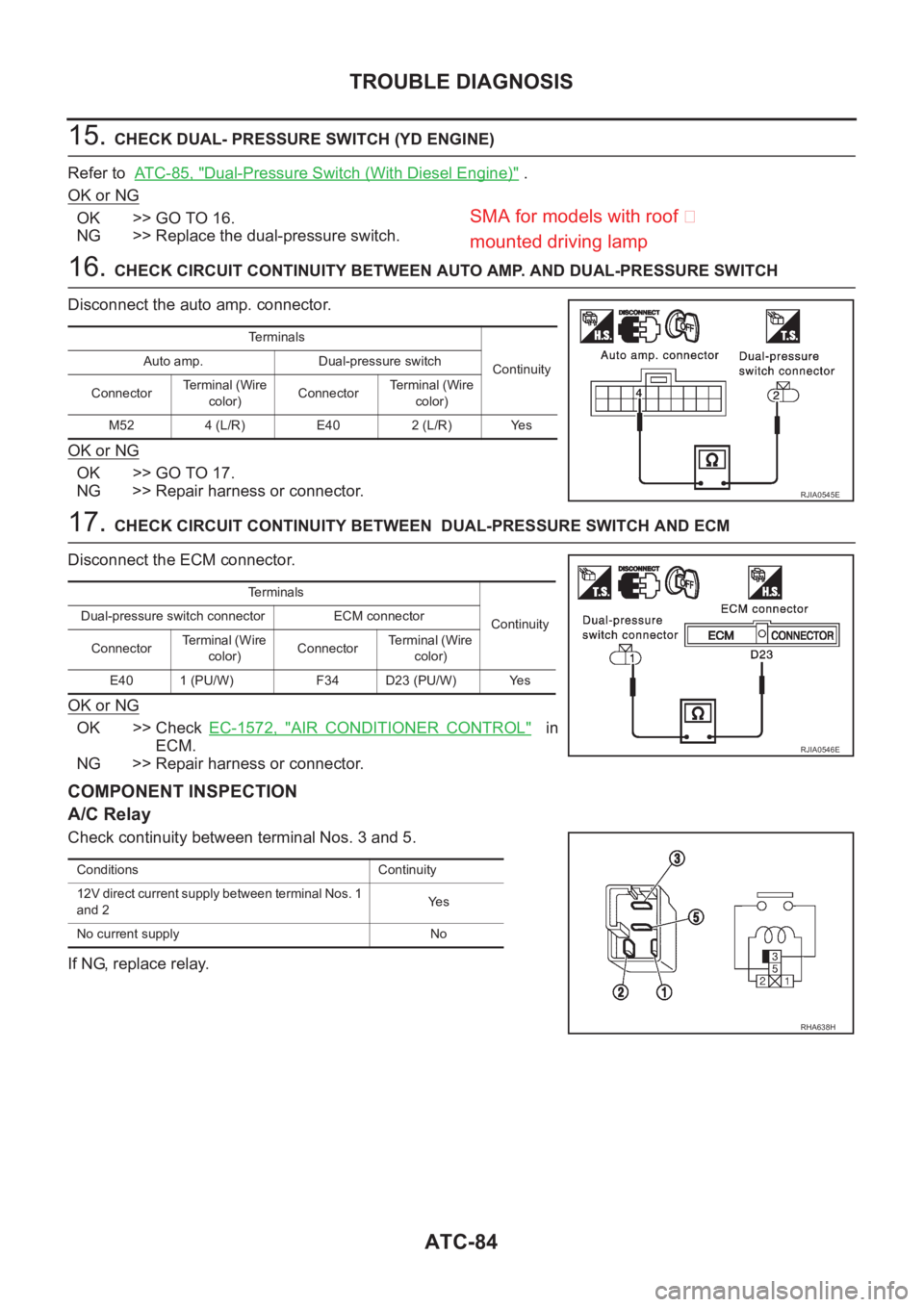
16. CHECK CIRCUIT CONTINUITY BETWEEN AUTO AMP. AND DUAL-PRESSURE SWITCH
Disconnect the auto amp. connector.
OK or NG
OK >> GO TO 17.
NG >> Repair harness or connector.
17. CHECK CIRCUIT CONTINUITY BETWEEN DUAL-PRESSURE SWITCH AND ECM
Disconnect the ECM connector.
OK or NG
OK >> Check EC-1572, "AIR CONDITIONER CONTROL" in
ECM.
NG >> Repair harness or connector.
COMPONENT INSPECTION
A/C Relay
Check continuity between terminal Nos. 3 and 5.
If NG, replace relay.
Terminals
Continuity Auto amp. Dual-pressure switch
ConnectorTerminal (Wire
color)ConnectorTerminal (Wire
color)
M52 4 (L/R) E40 2 (L/R) Yes
RJIA0545E
Terminals
Continuity Dual-pressure switch connector ECM connector
ConnectorTe r m i n a l ( W i r e
color)ConnectorTerminal (Wire
color)
E40 1 (PU/W) F34 D23 (PU/W) Yes
RJIA0546E
Conditions Continuity
12V direct current supply between terminal Nos. 1
and 2Ye s
No current supply No
RHA638H
SMA for models with roof �
mounted drivin
g lamp
Page 3361 of 3833
TROUBLE DIAGNOSIS
ATC-85
C
D
E
F
G
H
I
K
L
MA
B
AT C
Refrigerant Pressure Sensor (With Gasoline Engine)
The refrigerant pressure sensor is attached to the liquid tank (con-
denser).
Dual-Pressure Switch (With Diesel Engine)
Thermal Protector (With diesel engine)
Check continuity between compressor harness terminal and field
coil.
RJIA0690E
SHA315F
Compressor: ON
kPa (bar, kg/cm2 , psi)Compressor: OFF
kPa (bar, kg/cm2 , psi)
Low-pressure side 186 (1.86, 1.9, 27) 177 (1.77, 1.8, 26)
High-pressure side 1,569 (15.7, 16, 228) 2,746 (27.5, 28, 398)
RJIA0691E
RHA671H
Page 3363 of 3833
TROUBLE DIAGNOSIS
ATC-87
C
D
E
F
G
H
I
K
L
MA
B
AT C
*7ATC-78, "Magnet Clutch Circuit".*8AT C - 8 8 , "PERFORMANCE TEST
DIAGNOSES"
*9ATC-54, "Operational Check".
*10ATC-47, "
PROCEDURE", see No.5
to 7.*11 QR engine; EM-12, "Checking Drive
Belts" .
YD engine; EM-118, "
Checking Drive
Belts" .*12 QR25 engine; (WITH EURO-OBD)
EC-323, "
COOLING FAN CON-
TROL" .
QR25 engine; (WITHOOUT EUR-
OBD)EC-603, "
COOLING FAN
CONTROL" .
QR20 engine; (WITH EURO-OBD)
EC-1050, "
COOLING FAN CON-
TROL" .
QR20 engine; (WITHOUT EURO-
OBD)EC-1287, "
COOLING FAN
CONTROL" .
YD engine; EC-1508, "
SYSTEM
DESCRIPTION" .
Page 3365 of 3833
TROUBLE DIAGNOSIS
ATC-89
C
D
E
F
G
H
I
K
L
MA
B
AT C
*1ATC-135, "Removal and Installation
for Compressor Clutch".*2 \ ATC-70, "
Blower Motor Circuit" . *3 QR engine; EM-12, "Checking Drive
Belts" .
YD engine; EM-118, "
Checking Drive
Belts" .
RJIA1595E
Page 3368 of 3833
ATC-92
TROUBLE DIAGNOSIS
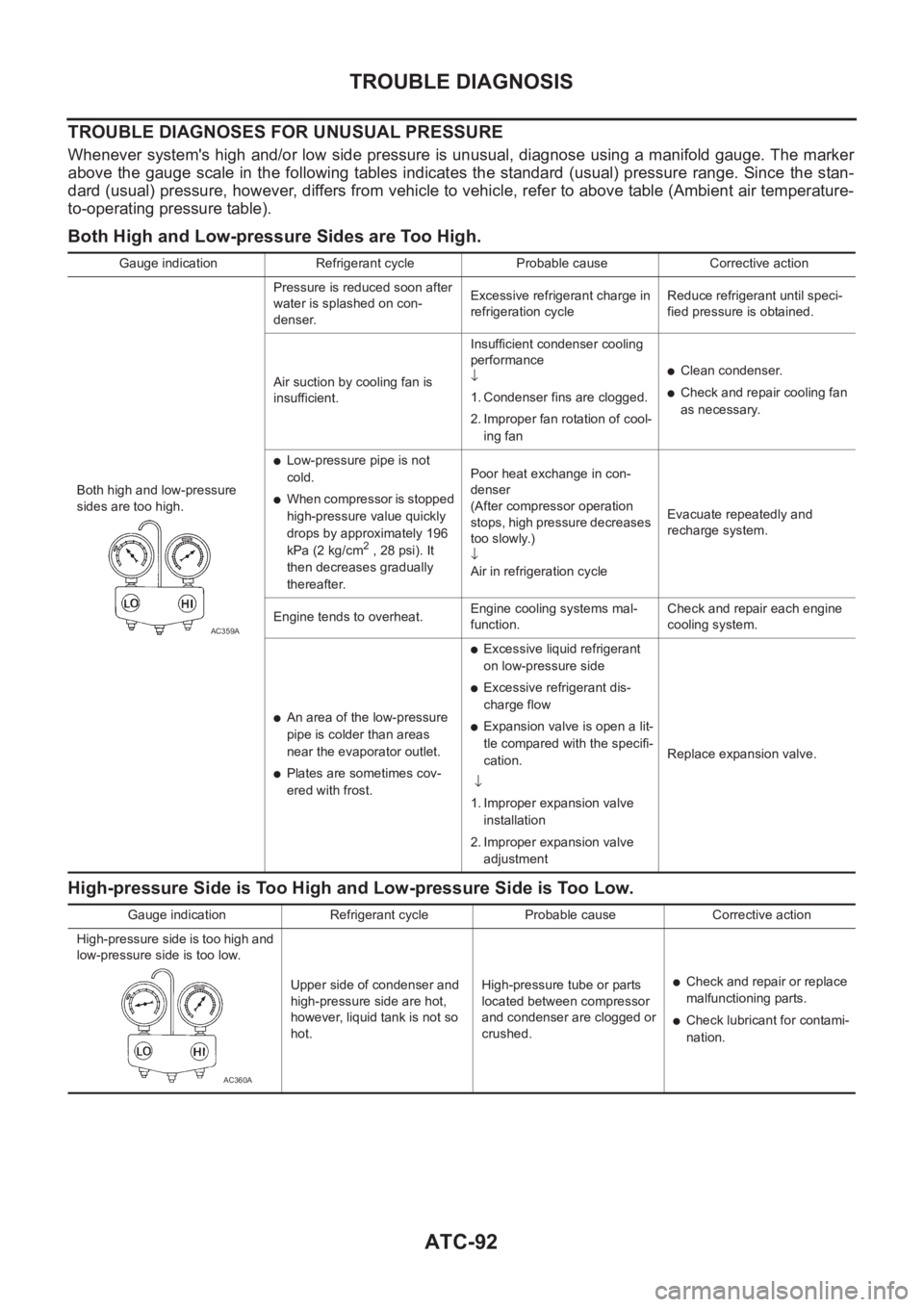
TROUBLE DIAGNOSES FOR UNUSUAL PRESSURE
Whenever system's high and/or low side pressure is unusual, diagnose using a manifold gauge. The marker
above the gauge scale in the following tables indicates the standard (usual) pressure range. Since the stan-
dard (usual) pressure, however, differs from vehicle to vehicle, refer to above table (Ambient air temperature-
to-operating pressure table).
Both High and Low-pressure Sides are Too High.
High-pressure Side is Too High and Low-pressure Side is Too Low.
Gauge indication Refrigerant cycle Probable cause Corrective action
Both high and low-pressure
sides are too high.Pressure is reduced soon after
water is splashed on con-
denser.Excessive refrigerant charge in
refrigeration cycleReduce refrigerant until speci-
fied pressure is obtained.
Air suction by cooling fan is
insufficient.Insufficient condenser cooling
performance
↓
1. Condenser fins are clogged.
2. Improper fan rotation of cool-
ing fan
●Clean condenser.
●Check and repair cooling fan
as necessary.
●Low-pressure pipe is not
cold.
●When compressor is stopped
high-pressure value quickly
drops by approximately 196
kPa (2 kg/cm
2 , 28 psi). It
then decreases gradually
thereafter.Poor heat exchange in con-
denser
(After compressor operation
stops, high pressure decreases
too slowly.)
↓
Air in refrigeration cycleEvacuate repeatedly and
recharge system.
Engine tends to overheat.Engine cooling systems mal-
function.Check and repair each engine
cooling system.
●An area of the low-pressure
pipe is colder than areas
near the evaporator outlet.
●Plates are sometimes cov-
ered with frost.
●Excessive liquid refrigerant
on low-pressure side
●Excessive refrigerant dis-
charge flow
●Expansion valve is open a lit-
tle compared with the specifi-
cation.
↓
1. Improper expansion valve
installation
2. Improper expansion valve
adjustmentReplace expansion valve.
AC359A
Gauge indication Refrigerant cycle Probable cause Corrective action
High-pressure side is too high and
low-pressure side is too low.
Upper side of condenser and
high-pressure side are hot,
however, liquid tank is not so
hot.High-pressure tube or parts
located between compressor
and condenser are clogged or
crushed.
●Check and repair or replace
malfunctioning parts.
●Check lubricant for contami-
nation.
AC360A