2001 NISSAN X-TRAIL check engine
[x] Cancel search: check enginePage 3471 of 3833
CHARGING SYSTEM
SC-15
C
D
E
F
G
H
I
J
L
MA
B
SC
Removal and Installation EKS0031A
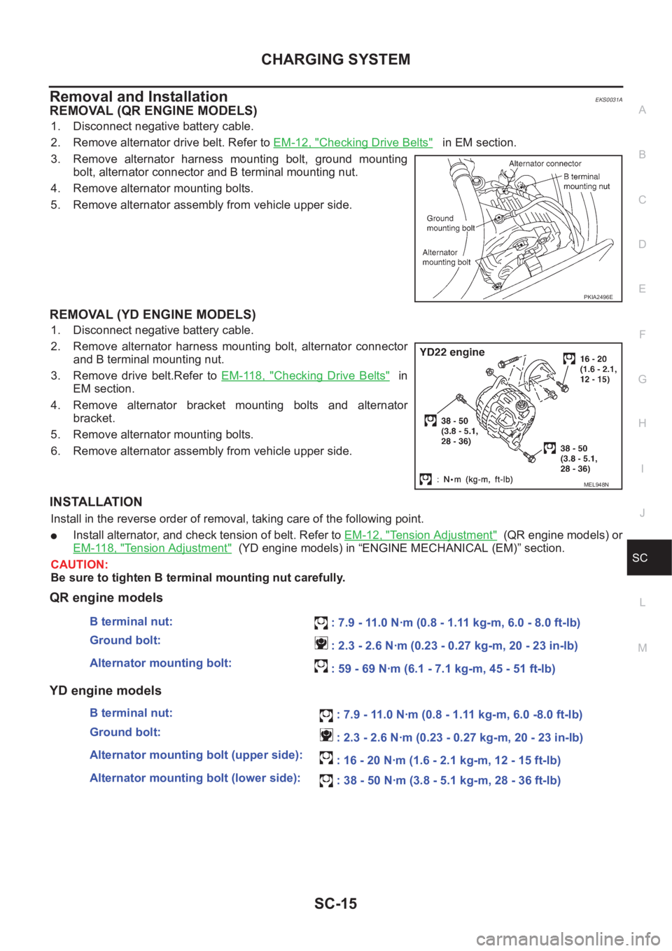
REMOVAL (QR ENGINE MODELS)
1. Disconnect negative battery cable.
2. Remove alternator drive belt. Refer to EM-12, "
Checking Drive Belts" in EM section.
3. Remove alternator harness mounting bolt, ground mounting
bolt, alternator connector and B terminal mounting nut.
4. Remove alternator mounting bolts.
5. Remove alternator assembly from vehicle upper side.
REMOVAL (YD ENGINE MODELS)
1. Disconnect negative battery cable.
2. Remove alternator harness mounting bolt, alternator connector
and B terminal mounting nut.
3. Remove drive belt.Refer to EM-118, "
Checking Drive Belts" in
EM section.
4. Remove alternator bracket mounting bolts and alternator
bracket.
5. Remove alternator mounting bolts.
6. Remove alternator assembly from vehicle upper side.
INSTALLATION
Install in the reverse order of removal, taking care of the following point.
●Install alternator, and check tension of belt. Refer to EM-12, "Tension Adjustment" (QR engine models) or
EM-118, "
Tension Adjustment" (YD engine models) in “ENGINE MECHANICAL (EM)” section.
CAUTION:
Be sure to tighten B terminal mounting nut carefully.
QR engine models
YD engine models
PKIA2496E
MEL948N
B terminal nut:
: 7.9 - 11.0 N·m (0.8 - 1.11 kg-m, 6.0 - 8.0 ft-lb)
Ground bolt:
: 2.3 - 2.6 N·m (0.23 - 0.27 kg-m, 20 - 23 in-lb)
Alternator mounting bolt:
: 59 - 69 N·m (6.1 - 7.1 kg-m, 45 - 51 ft-lb)
B terminal nut:
: 7.9 - 11.0 N·m (0.8 - 1.11 kg-m, 6.0 -8.0 ft-lb)
Ground bolt:
: 2.3 - 2.6 N·m (0.23 - 0.27 kg-m, 20 - 23 in-lb)
Alternator mounting bolt (upper side):
: 16 - 20 N·m (1.6 - 2.1 kg-m, 12 - 15 ft-lb)
Alternator mounting bolt (lower side):
: 38 - 50 N·m (3.8 - 5.1 kg-m, 28 - 36 ft-lb)
Page 3487 of 3833
STARTING SYSTEM
SC-31
C
D
E
F
G
H
I
J
L
MA
B
SC
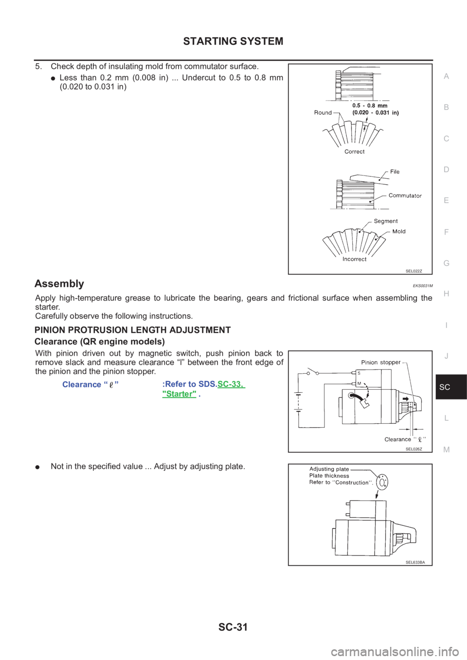
5. Check depth of insulating mold from commutator surface.
●Less than 0.2 mm (0.008 in) ... Undercut to 0.5 to 0.8 mm
(0.020 to 0.031 in)
AssemblyEKS0031M
Apply high-temperature grease to lubricate the bearing, gears and frictional surface when assembling the
starter.
Carefully observe the following instructions.
PINION PROTRUSION LENGTH ADJUSTMENT
Clearance (QR engine models)
With pinion driven out by magnetic switch, push pinion back to
remove slack and measure clearance “l” between the front edge of
the pinion and the pinion stopper.
●Not in the specified value ... Adjust by adjusting plate.
SEL022Z
Clearance “ ”:Refer to SDS.SC-33,
"Starter" .
SEL026Z
SEL633BA
Page 3496 of 3833
LT-6
HEADLAMP
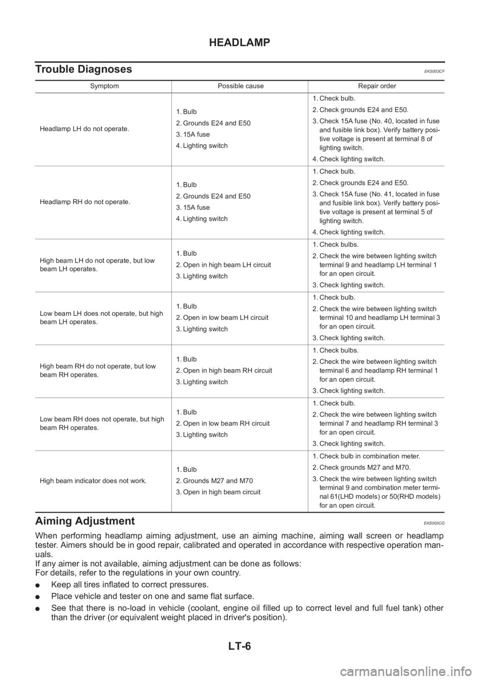
Trouble Diagnoses
EKS003CF
Aiming Adjustment EKS003CG
When performing headlamp aiming adjustment, use an aiming machine, aiming wall screen or headlamp
tester. Aimers should be in good repair, calibrated and operated in accordance with respective operation man-
uals.
If any aimer is not available, aiming adjustment can be done as follows:
For details, refer to the regulations in your own country.
●Keep all tires inflated to correct pressures.
●Place vehicle and tester on one and same flat surface.
●See that there is no-load in vehicle (coolant, engine oil filled up to correct level and full fuel tank) other
than the driver (or equivalent weight placed in driver's position).
Symptom Possible cause Repair order
Headlamp LH do not operate.1. Bulb
2. Grounds E24 and E50
3. 15A fuse
4. Lighting switch1. Check bulb.
2. Check grounds E24 and E50.
3. Check 15A fuse (No. 40, located in fuse
and fusible link box). Verify battery posi-
tive voltage is present at terminal 8 of
lighting switch.
4. Check lighting switch.
Headlamp RH do not operate.1. Bulb
2. Grounds E24 and E50
3. 15A fuse
4. Lighting switch1. Check bulb.
2. Check grounds E24 and E50.
3. Check 15A fuse (No. 41, located in fuse
and fusible link box). Verify battery posi-
tive voltage is present at terminal 5 of
lighting switch.
4. Check lighting switch.
High beam LH do not operate, but low
beam LH operates.1. Bulb
2. Open in high beam LH circuit
3. Lighting switch1. Check bulbs.
2. Check the wire between lighting switch
terminal 9 and headlamp LH terminal 1
for an open circuit.
3. Check lighting switch.
Low beam LH does not operate, but high
beam LH operates.1. Bulb
2. Open in low beam LH circuit
3. Lighting switch1. Check bulb.
2. Check the wire between lighting switch
terminal 10 and headlamp LH terminal 3
for an open circuit.
3. Check lighting switch.
High beam RH do not operate, but low
beam RH operates.1. Bulb
2. Open in high beam RH circuit
3. Lighting switch1. Check bulbs.
2. Check the wire between lighting switch
terminal 6 and headlamp RH terminal 1
for an open circuit.
3. Check lighting switch.
Low beam RH does not operate, but high
beam RH operates.1. Bulb
2. Open in low beam RH circuit
3. Lighting switch1. Check bulb.
2. Check the wire between lighting switch
terminal 7 and headlamp RH terminal 3
for an open circuit.
3. Check lighting switch.
High beam indicator does not work.1. Bulb
2. Grounds M27 and M70
3. Open in high beam circuit1. Check bulb in combination meter.
2. Check grounds M27 and M70.
3. Check the wire between lighting switch
terminal 9 and combination meter termi-
nal 61(LHD models) or 50(RHD models)
for an open circuit.
Page 3559 of 3833
DI-1
DRIVER INFORMATION SYSTEM
K ELECTRICAL
CONTENTS
C
D
E
F
G
H
I
J
L
M
SECTION
A
B
DI
DRIVER INFORMATION SYSTEM
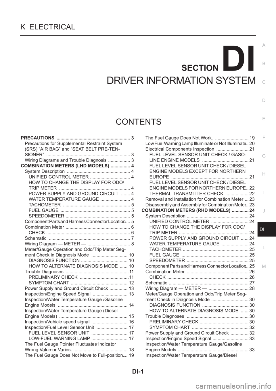
PRECAUTIONS .......................................................... 3
Precautions for Supplemental Restraint System
(SRS) “AIR BAG” and “SEAT BELT PRE-TEN-
SIONER” .................................................................. 3
Wiring Diagrams and Trouble Diagnosis .................. 3
COMBINATION METERS (LHD MODELS) ................ 4
System Description .................................................. 4
UNIFIED CONTROL METER ................................ 4
HOW TO CHANGE THE DISPLAY FOR ODO/
TRIP METER ........................................................ 4
POWER SUPPLY AND GROUND CIRCUIT ........ 4
WATER TEMPERATURE GAUGE ........................ 4
TACHOMETER ..................................................... 5
FUEL GAUGE ....................................................... 5
SPEEDOMETER ................................................... 5
Component Parts and Harness Connector Location ..... 5
Combination Meter ................................................... 6
CHECK .................................................................. 6
Schematic ................................................................ 7
Wiring Diagram — METER — .................................. 8
Meter/Gauge Operation and Odo/Trip Meter Seg-
ment Check in Diagnosis Mode ............................. 10
DIAGNOSIS FUNCTION ..................................... 10
HOW TO ALTERNATE DIAGNOSIS MODE ....... 10
Trouble Diagnoses .................................................. 11
PRELIMINARY CHECK ....................................... 11
SYMPTOM CHART ............................................. 12
Power Supply and Ground Circuit Check ............... 13
Inspection/Engine Speed Signal ............................ 13
Inspection/Water Temperature Gauge /Gasoline
Engine Models ....................................................... 14
Inspection/Water Temperature Gauge (Diesel
Engine Models) ...................................................... 15
Inspection/Vehicle speed signal ............................. 16
Inspection/Fuel Level Sensor Unit ......................... 17
FUEL LEVEL SENSOR UNIT ............................. 17
LOW-FUEL WARNING LAMP ............................. 17
The Fuel Gauge Pointer Fluctuates·Indicator
Wrong Value·or Varies. ........................................... 18
The Fuel Gauge Does Not Move to Full-position. ... 19The Fuel Gauge Does Not Work. ........................... 19
Low Fuel Warning Lamp Illuminate or Not Illuminate ... 20
Electrical Components Inspection .......................... 21
FUEL LEVEL SENSOR UNIT CHECK / GASO-
LINE ENGINE MODELS ..................................... 21
FUEL LEVEL SENSOR UNIT CHECK / DIESEL
ENGINE MODELS EXCEPT FOR NORTHERN
EUROPE ............................................................. 21
FUEL LEVEL SENSOR UNIT CHECK / DIESEL
ENGINE MODELS FOR NORTHERN EUROPE ... 22
THERMAL TRANSMITTER CHECK ................... 22
Removal and Installation for Combination Meter .... 23
Disassembly and Assembly for Combination Meter ... 23
COMBINATION METERS (RHD MODELS) .............. 24
System Description ................................................. 24
UNIFIED CONTROL METER ...........................
... 24
HOW TO CHANGE THE DISPLAY FOR ODO/
TRIP METER ....................................................... 24
POWER SUPPLY AND GROUND CIRCUIT ....... 24
WATER TEMPERATURE GAUGE ...................... 24
TACHOMETER .................................................... 25
FUEL GAUGE ..................................................... 25
SPEEDOMETER ................................................. 25
Component Parts and Harness Connector Location ... 25
Combination Meter .............................................. ... 26
CHECK ................................................................ 26
Schematic ............................................................... 27
Wiring Diagram — METER — ................................ 28
Meter/Gauge Operation and Odo/Trip Meter Seg-
ment Check in Diagnosis Mode .............................. 30
DIAGNOSIS FUNCTION ..................................... 30
HOW TO ALTERNATE DIAGNOSIS MODE ....... 30
Trouble Diagnoses ................................................. 30
PRELIMINARY CHECK ....................................... 30
SYMPTOM CHART ............................................. 32
Power Supply and Ground Circuit Check ............... 32
Inspection/Engine Speed Signal ............................. 33
Inspection/Water Temperature Gauge/Gasoline
Engine Models ........................................................ 33
Inspection/Water Temperature Gauge/Diesel
Page 3560 of 3833
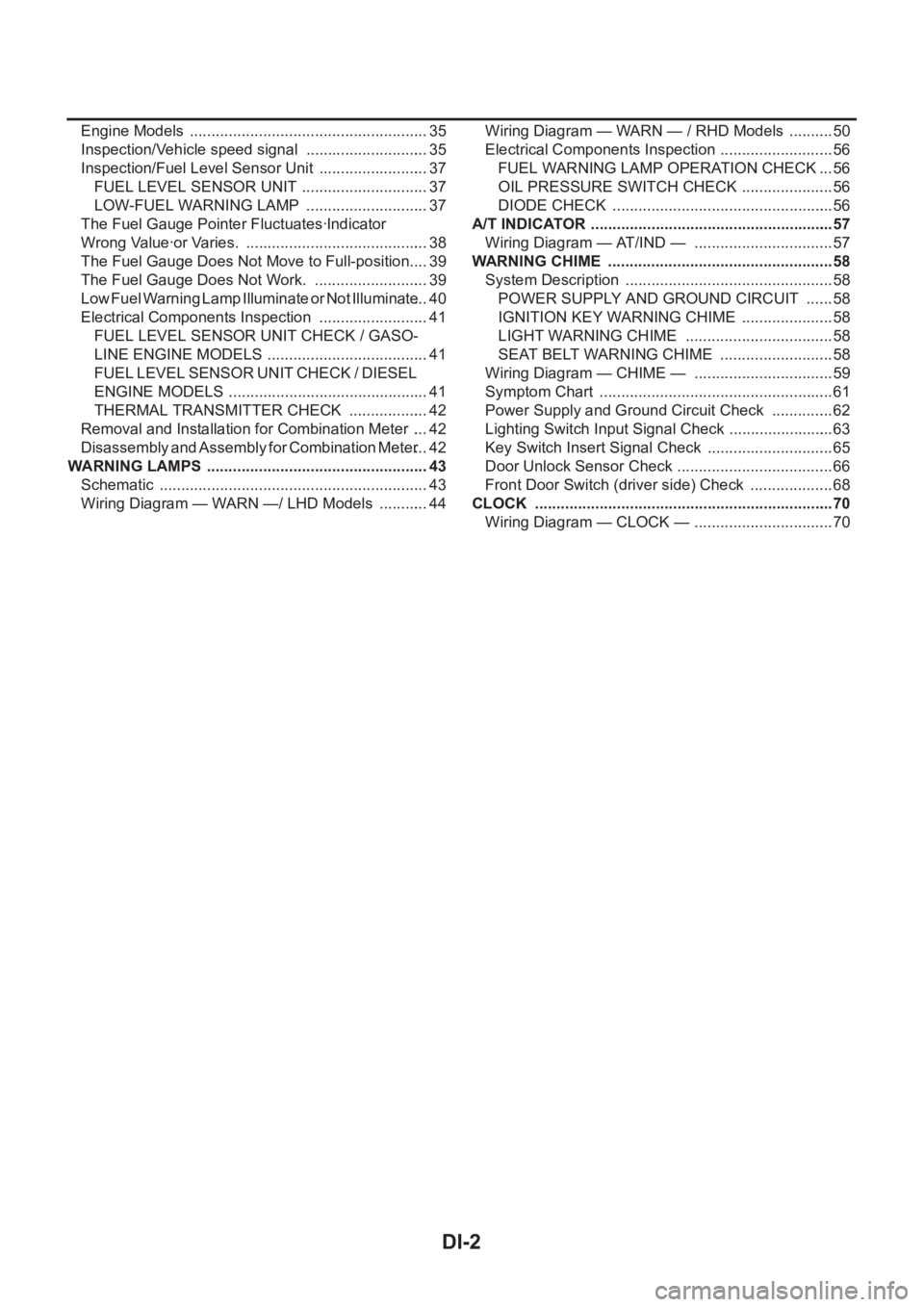
DI-2
Engine Models ........................................................ 35
Inspection/Vehicle speed signal ............................. 35
Inspection/Fuel Level Sensor Unit .......................... 37
FUEL LEVEL SENSOR UNIT .............................. 37
LOW-FUEL WARNING LAMP ............................. 37
The Fuel Gauge Pointer Fluctuates·Indicator
Wrong Value·or Varies. ........................................... 38
The Fuel Gauge Does Not Move to Full-position. ... 39
The Fuel Gauge Does Not Work. ........................... 39
Low Fuel Warning Lamp Illuminate or Not Illuminate ... 40
Electrical Components Inspection .......................... 41
FUEL LEVEL SENSOR UNIT CHECK / GASO-
LINE ENGINE MODELS ...................................... 41
FUEL LEVEL SENSOR UNIT CHECK / DIESEL
ENGINE MODELS ............................................... 41
THERMAL TRANSMITTER CHECK ................... 42
Removal and Installation for Combination Meter .... 42
Disassembly and Assembly for Combination Meter ... 42
WARNING LAMPS .................................................... 43
Schematic ............................................................... 43
Wiring Diagram — WARN —/ LHD Models ............ 44Wiring Diagram — WARN — / RHD Models ........... 50
Electrical Components Inspection ........................... 56
FUEL WARNING LAMP OPERATION CHECK ... 56
OIL PRESSURE SWITCH CHECK ...................... 56
DIODE CHECK .................................................... 56
A/T INDICATOR ......................................................... 57
Wiring Diagram — AT/IND — ................................. 57
WARNING CHIME .................................................. ... 58
System Description ................................................. 58
POWER SUPPLY AND GROUND CIRCUIT ....... 58
IGNITION KEY WARNING CHIME ...................... 58
LIGHT WARNING CHIME ................................... 58
SEAT BELT WARNING CHIME ........................... 58
Wiring Diagram — CHIME — ................................. 59
Symptom Chart ....................................................... 61
Power Supply and Ground Circuit Check ............... 62
Lighting Switch Input Signal Check ......................... 63
Key Switch Insert Signal Check .............................. 65
Door Unlock Sensor Check ..................................... 66
Front Door Switch (driver side) Check .................... 68
CLOCK ...................................................................... 70
Wiring Diagram — CLOCK — ................................. 70
Page 3562 of 3833
DI-4
COMBINATION METERS (LHD MODELS)
COMBINATION METERS (LHD MODELS)
PFP:24810
System DescriptionEKS002Z7
UNIFIED CONTROL METER
●Speedometer, odo/trip meter, tachometer, fuel gauge and water temperature gauge are controlled totally
by control unit built-in combination meter.
●Digital meter is adopted for odo/trip meter.*
*The record of the odo meter is kept even if the battery cable is disconnected. The record of the trip meter
is erased when the battery cable is disconnected.
●Odo/trip meter segment can be checked in diagnosis mode.
●Meter/gauge can be checked in diagnosis mode.
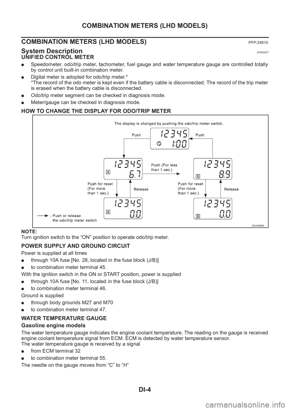
HOW TO CHANGE THE DISPLAY FOR ODO/TRIP METER
NOTE:
Turn ignition switch to the “ON” position to operate odo/trip meter.
POWER SUPPLY AND GROUND CIRCUIT
Power is supplied at all times
●through 10A fuse [No. 28, located in the fuse block (J/B)]
●to combination meter terminal 45.
With the ignition switch in the ON or START position, power is supplied
●through 10A fuse [No. 11, located in the fuse block (J/B)]
●to combination meter terminal 46.
Ground is supplied
●through body grounds M27 and M70
●to combination meter terminal 47.
WATER TEMPERATURE GAUGE
Gasoline engine models
The water temperature gauge indicates the engine coolant temperature. The reading on the gauge is received
engine coolant temperature signal from ECM. ECM is detected by water temperature sensor.
The water temperature gauge is received by a signal
●from ECM terminal 32
●to combination meter terminal 55.
The needle on the gauge moves from “C” to “H”
SKIA0896E
Page 3570 of 3833
DI-12
COMBINATION METERS (LHD MODELS)
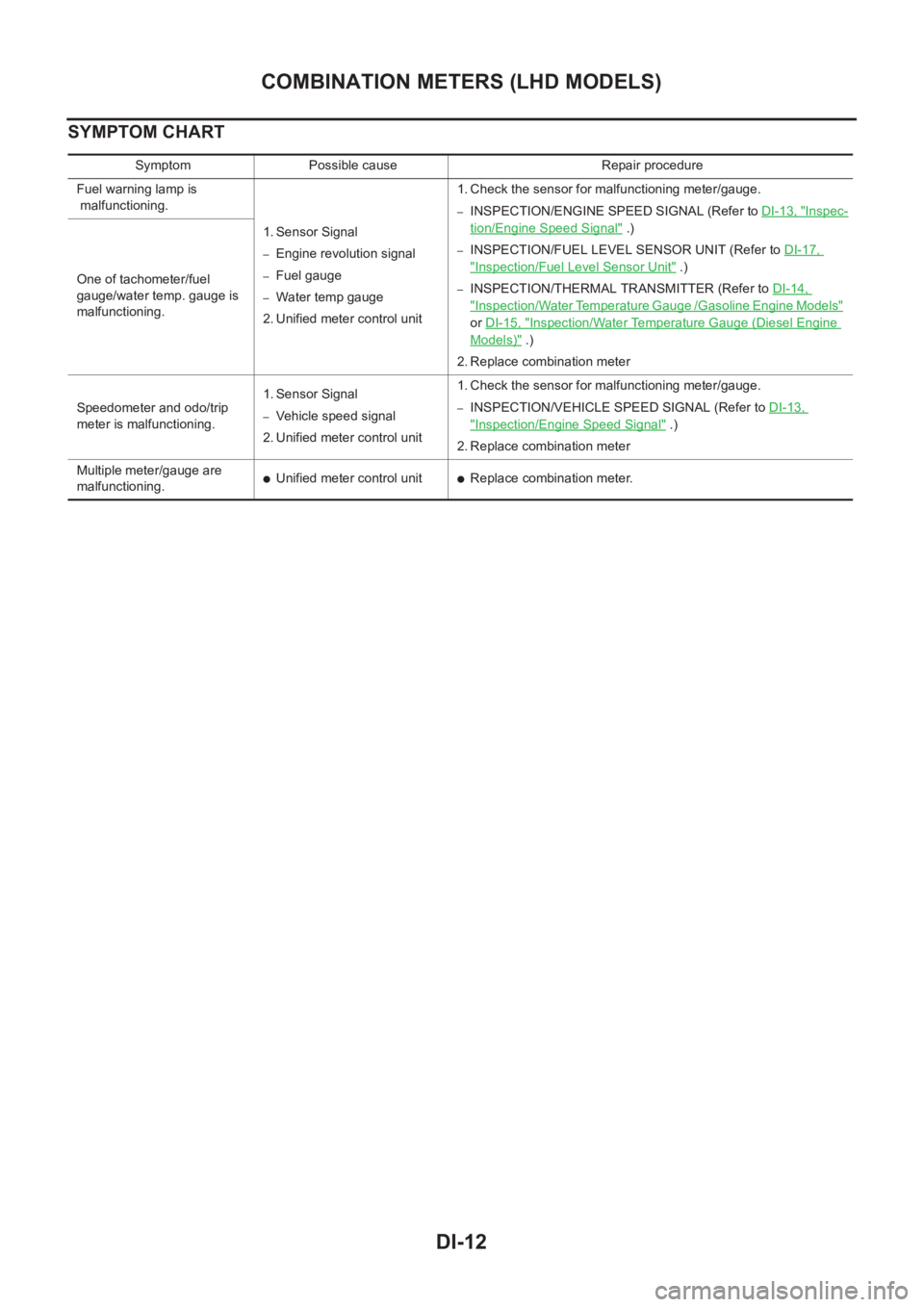
SYMPTOM CHART
Symptom Possible cause Repair procedure
Fuel warning lamp is
malfunctioning.
1. Sensor Signal
–Engine revolution signal
–Fuel gauge
–Water temp gauge
2. Unified meter control unit 1. Check the sensor for malfunctioning meter/gauge.
–INSPECTION/ENGINE SPEED SIGNAL (Refer to DI-13, "Inspec-
tion/Engine Speed Signal" .)
–INSPECTION/FUEL LEVEL SENSOR UNIT (Refer to DI-17,
"Inspection/Fuel Level Sensor Unit" .)
–INSPECTION/THERMAL TRANSMITTER (Refer to DI-14,
"Inspection/Water Temperature Gauge /Gasoline Engine Models"
or DI-15, "Inspection/Water Temperature Gauge (Diesel Engine
Models)" .)
2. Replace combination meter One of tachometer/fuel
gauge/water temp. gauge is
malfunctioning.
Speedometer and odo/trip
meter is malfunctioning.1. Sensor Signal
–Vehicle speed signal
2. Unified meter control unit 1. Check the sensor for malfunctioning meter/gauge.–INSPECTION/VEHICLE SPEED SIGNAL (Refer to DI-13,
"Inspection/Engine Speed Signal" .)
2. Replace combination meter
Multiple meter/gauge are
malfunctioning.
●Unified meter control unit●Replace combination meter.
Page 3571 of 3833
COMBINATION METERS (LHD MODELS)
DI-13
C
D
E
F
G
H
I
J
L
MA
B
DI
Power Supply and Ground Circuit CheckEKS002ZE
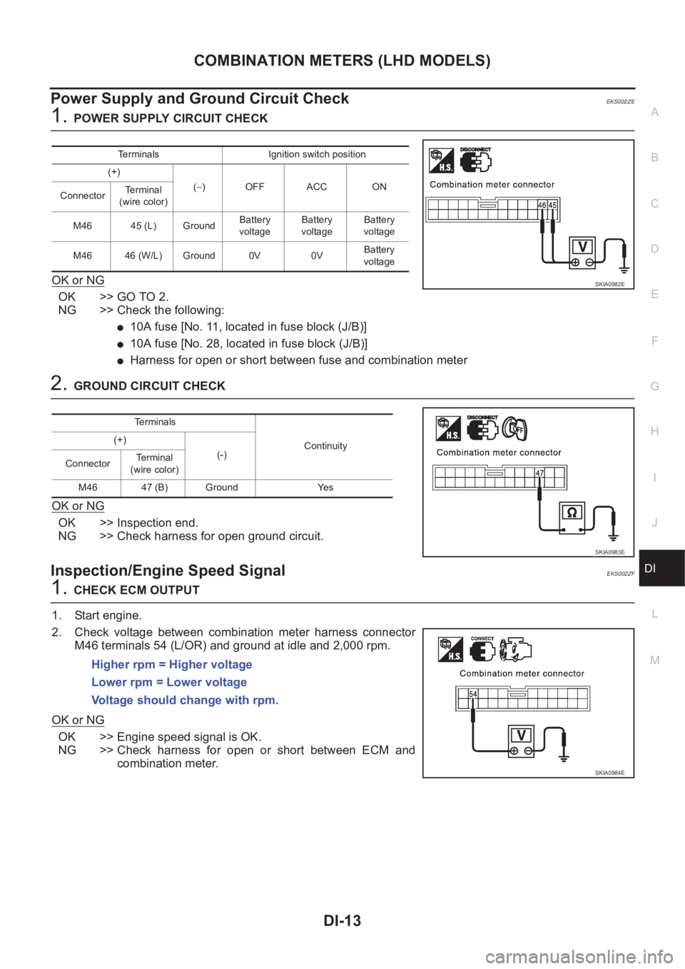
1.POWER SUPPLY CIRCUIT CHECK
OK or NG
OK >> GO TO 2.
NG >> Check the following:
●10A fuse [No. 11, located in fuse block (J/B)]
●10A fuse [No. 28, located in fuse block (J/B)]
●Harness for open or short between fuse and combination meter
2.GROUND CIRCUIT CHECK
OK or NG
OK >> Inspection end.
NG >> Check harness for open ground circuit.
Inspection/Engine Speed SignalEKS002ZF
1.CHECK ECM OUTPUT
1. Start engine.
2. Check voltage between combination meter harness connector
M46 terminals 54 (L/OR) and ground at idle and 2,000 rpm.
OK or NG
OK >> Engine speed signal is OK.
NG >> Check harness for open or short between ECM and
combination meter.
Terminals Ignition switch position
(+)
(−)OFF ACC ON
ConnectorTerminal
(wire color)
M46 45 (L) GroundBattery
voltageBattery
voltageBattery
voltage
M46 46 (W/L) Ground 0V 0VBattery
voltage
SKIA0982E
Terminals
Continuity (+)
(-)
ConnectorTerminal
(wire color)
M46 47 (B) Ground Yes
SKIA0983E
Higher rpm = Higher voltage
Lower rpm = Lower voltage
Voltage should change with rpm.
SKIA0984E