Page 3597 of 3833

COMBINATION METERS (RHD MODELS)
DI-39
C
D
E
F
G
H
I
J
L
MA
B
DI
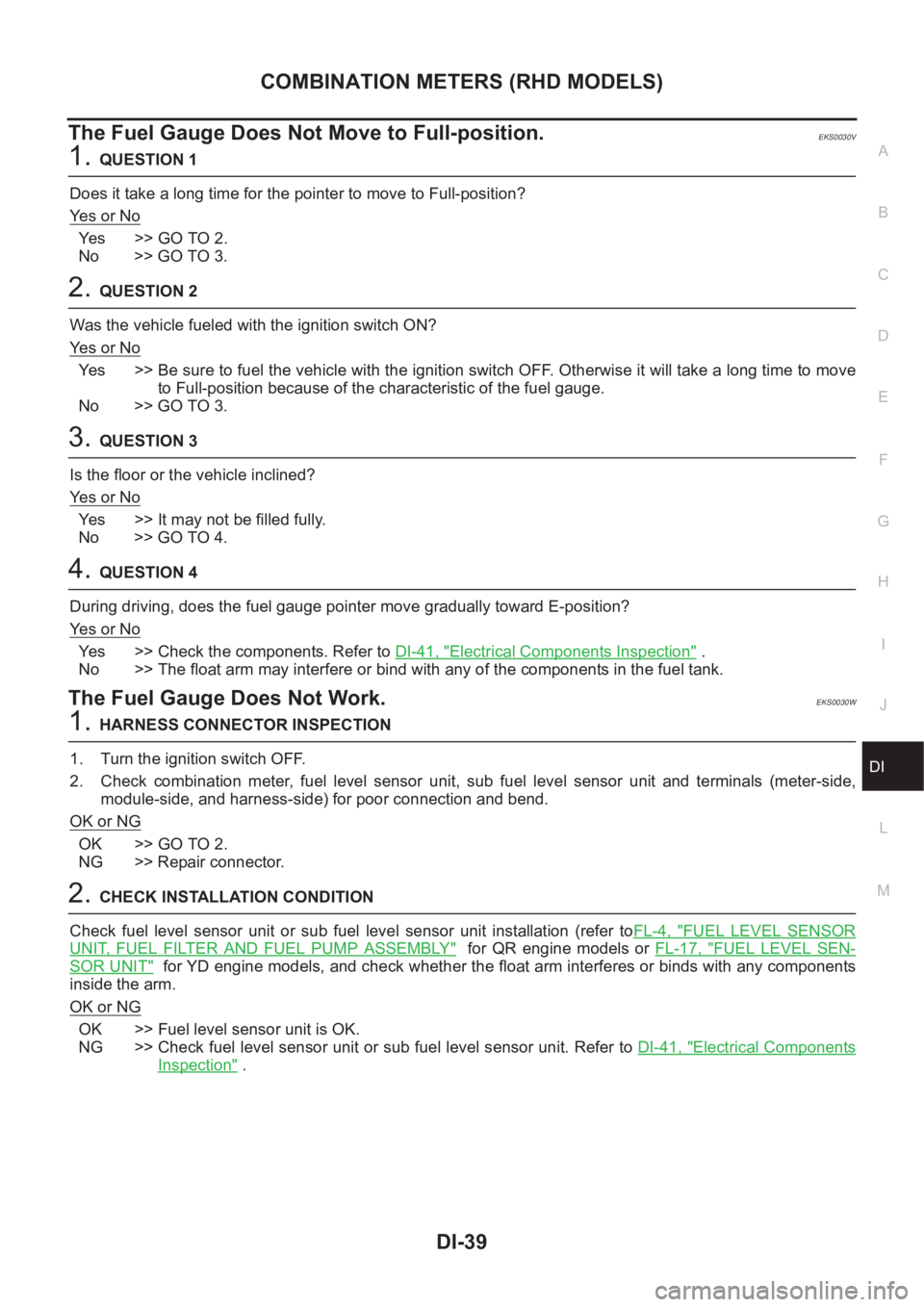
The Fuel Gauge Does Not Move to Full-position.EKS0030V
1.QUESTION 1
Does it take a long time for the pointer to move to Full-position?
Ye s o r N o
Ye s > > G O T O 2 .
No >> GO TO 3.
2.QUESTION 2
Was the vehicle fueled with the ignition switch ON?
Ye s o r N o
Yes >> Be sure to fuel the vehicle with the ignition switch OFF. Otherwise it will take a long time to move
to Full-position because of the characteristic of the fuel gauge.
No >> GO TO 3.
3.QUESTION 3
Is the floor or the vehicle inclined?
Ye s o r N o
Yes >> It may not be filled fully.
No >> GO TO 4.
4.QUESTION 4
During driving, does the fuel gauge pointer move gradually toward E-position?
Ye s o r N o
Yes >> Check the components. Refer to DI-41, "Electrical Components Inspection" .
No >> The float arm may interfere or bind with any of the components in the fuel tank.
The Fuel Gauge Does Not Work.EKS0030W
1.HARNESS CONNECTOR INSPECTION
1. Turn the ignition switch OFF.
2. Check combination meter, fuel level sensor unit, sub fuel level sensor unit and terminals (meter-side,
module-side, and harness-side) for poor connection and bend.
OK or NG
OK >> GO TO 2.
NG >> Repair connector.
2.CHECK INSTALLATION CONDITION
Check fuel level sensor unit or sub fuel level sensor unit installation (refer toFL-4, "
FUEL LEVEL SENSOR
UNIT, FUEL FILTER AND FUEL PUMP ASSEMBLY" for QR engine models or FL-17, "FUEL LEVEL SEN-
SOR UNIT" for YD engine models, and check whether the float arm interferes or binds with any components
inside the arm.
OK or NG
OK >> Fuel level sensor unit is OK.
NG >> Check fuel level sensor unit or sub fuel level sensor unit. Refer to DI-41, "
Electrical Components
Inspection" .
Page 3599 of 3833

COMBINATION METERS (RHD MODELS)
DI-41
C
D
E
F
G
H
I
J
L
MA
B
DI
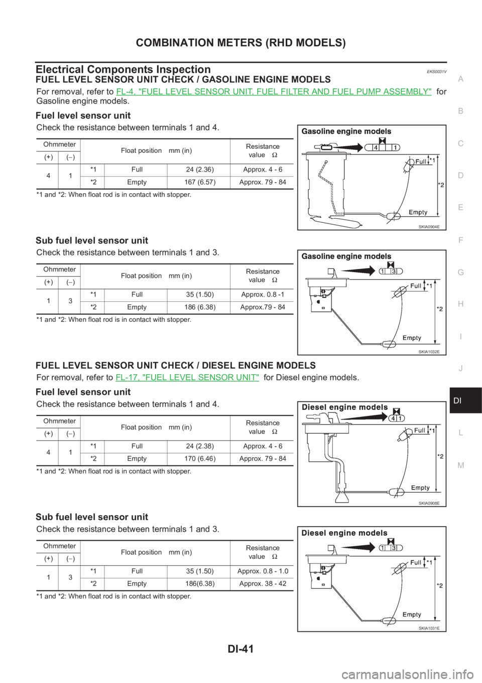
Electrical Components InspectionEKS0031V
FUEL LEVEL SENSOR UNIT CHECK / GASOLINE ENGINE MODELS
For removal, refer to FL-4, "FUEL LEVEL SENSOR UNIT, FUEL FILTER AND FUEL PUMP ASSEMBLY" for
Gasoline engine models.
Fuel level sensor unit
Check the resistance between terminals 1 and 4.
*1 and *2: When float rod is in contact with stopper.
Sub fuel level sensor unit
Check the resistance between terminals 1 and 3.
*1 and *2: When float rod is in contact with stopper.
FUEL LEVEL SENSOR UNIT CHECK / DIESEL ENGINE MODELS
For removal, refer to FL-17, "FUEL LEVEL SENSOR UNIT" for Diesel engine models.
Fuel level sensor unit
Check the resistance between terminals 1 and 4.
*1 and *2: When float rod is in contact with stopper.
Sub fuel level sensor unit
Check the resistance between terminals 1 and 3.
*1 and *2: When float rod is in contact with stopper.Ohmmeter
Float position mm (in)Resistance
valueΩ
(+) (−)
41*1 Full 24 (2.36) Approx. 4 - 6
*2 Empty 167 (6.57) Approx. 79 - 84
SKIA0904E
Ohmmeter
Float position mm (in)Resistance
valueΩ
(+) (−)
13*1 Full 35 (1.50) Approx. 0.8 -1
*2 Empty 186 (6.38) Approx.79 - 84
SKIA1032E
Ohmmeter
Float position mm (in)Resistance
valueΩ
(+) (−)
41*1 Full 24 (2.38) Approx. 4 - 6
*2 Empty 170 (6.46) Approx. 79 - 84
SKIA0908E
Ohmmeter
Float position mm (in)Resistance
valueΩ
(+) (−)
13*1 Full 35 (1.50) Approx. 0.8 - 1.0
*2 Empty 186(6.38) Approx. 38 - 42
SKIA1031E
Page 3614 of 3833

DI-56
WARNING LAMPS
Electrical Components Inspection
EKS002HK
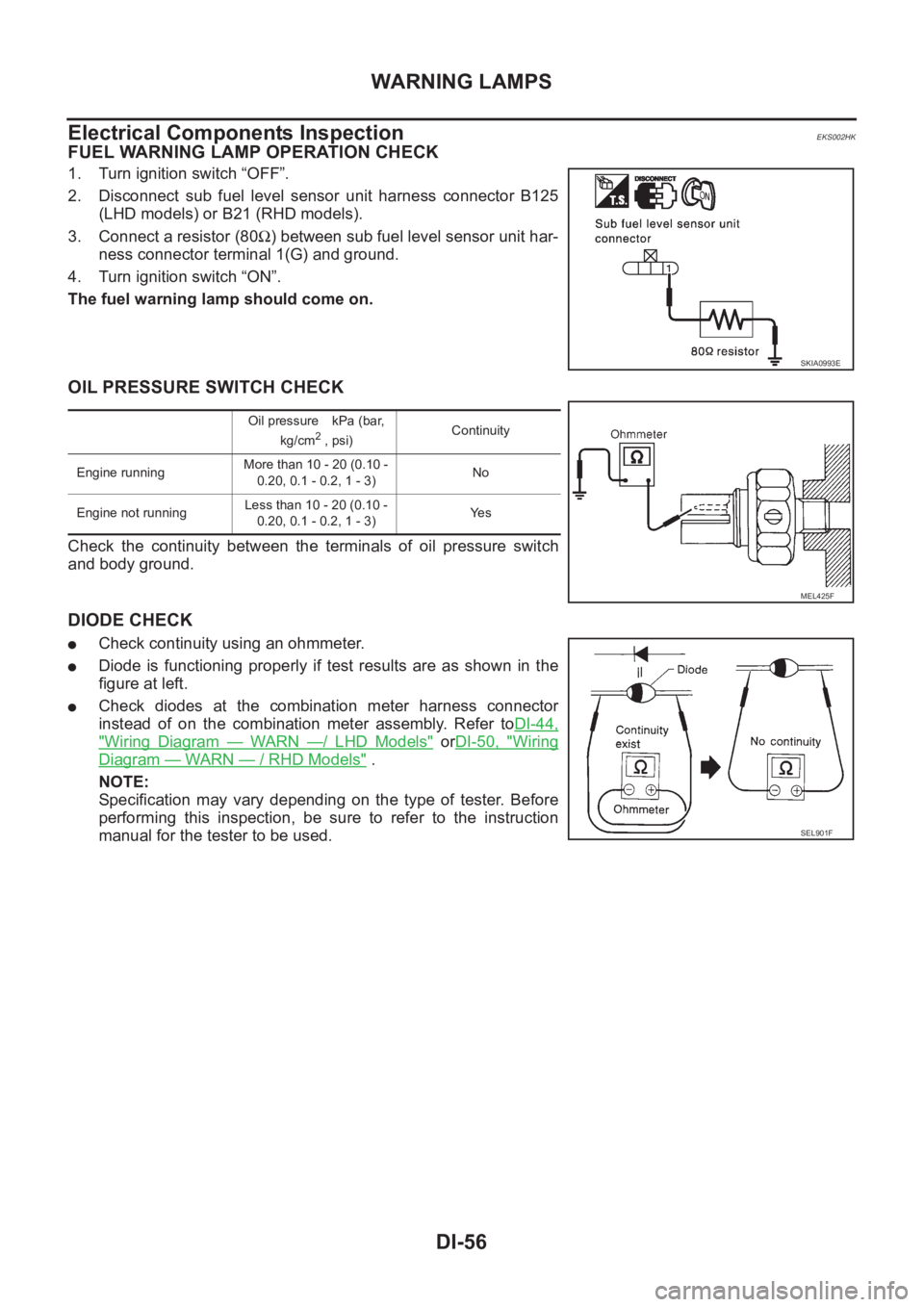
FUEL WARNING LAMP OPERATION CHECK
1. Turn ignition switch “OFF”.
2. Disconnect sub fuel level sensor unit harness connector B125
(LHD models) or B21 (RHD models).
3. Connect a resistor (80Ω) between sub fuel level sensor unit har-
ness connector terminal 1(G) and ground.
4. Turn ignition switch “ON”.
The fuel warning lamp should come on.
OIL PRESSURE SWITCH CHECK
Check the continuity between the terminals of oil pressure switch
and body ground.
DIODE CHECK
●Check continuity using an ohmmeter.
●Diode is functioning properly if test results are as shown in the
figure at left.
●Check diodes at the combination meter harness connector
instead of on the combination meter assembly. Refer toDI-44,
"Wiring Diagram — WARN —/ LHD Models" orDI-50, "Wiring
Diagram — WARN — / RHD Models" .
NOTE:
Specification may vary depending on the type of tester. Before
performing this inspection, be sure to refer to the instruction
manual for the tester to be used.
SKIA0993E
Oil pressure kPa (bar,
kg/cm2 , psi)Continuity
Engine runningMore than 10 - 20 (0.10 -
0.20, 0.1 - 0.2, 1 - 3)No
Engine not runningLess than 10 - 20 (0.10 -
0.20, 0.1 - 0.2, 1 - 3)Ye s
MEL425F
SEL901F
Page 3639 of 3833
FRONT WIPER AND WASHER SYSTEM
WW-11
C
D
E
F
G
H
I
J
L
MA
B
WW
Removal and Installation for Washer Nozzle EKS0032U
REMOVAL
1. Push washer nozzle pawl toward engine hood to pull out.
INSTALLATION
1. After connecting washer hose, press nozzle from cowl top cover surface.
2. Assemble nozzle and socket.
3. Adjust nozzle injection position.
Inspection for Washer Nozzle EKS0032V
CHECK VALVE
●Blow air in the injection direction, and check that air flows only
one way. Make sure that the reverse direction (inhale) is not
possible.
Removal and Installation for Wiper and Washer Switch EKS0032W
REMOVAL
1. Remove steering column cover.
2. Remove wiper washer switch connector.
3. Remove two screws then remove wiper washer switch from the
base.
INSTALLATION
Installation is in the reverse order of removal.
PKIA0481E
PKIA0482E
SKIA0018E
Page 3669 of 3833
![NISSAN X-TRAIL 2001 Service Repair Manual CAN SYSTEM (FOR A/T MODELS)
LAN-7
[CAN]
C
D
E
F
G
H
I
J
L
MA
B
LAN
Work FlowEKS002AG
1. Print all the data of “SELF-DIAG RESULTS” and “DATA MONITOR” for “ENGINE” and “A/T” displayed on NISSAN X-TRAIL 2001 Service Repair Manual CAN SYSTEM (FOR A/T MODELS)
LAN-7
[CAN]
C
D
E
F
G
H
I
J
L
MA
B
LAN
Work FlowEKS002AG
1. Print all the data of “SELF-DIAG RESULTS” and “DATA MONITOR” for “ENGINE” and “A/T” displayed on](/manual-img/5/57405/w960_57405-3668.png)
CAN SYSTEM (FOR A/T MODELS)
LAN-7
[CAN]
C
D
E
F
G
H
I
J
L
MA
B
LAN
Work FlowEKS002AG
1. Print all the data of “SELF-DIAG RESULTS” and “DATA MONITOR” for “ENGINE” and “A/T” displayed on
CONSULT-II. Refer to the following:
●EC-854, "DTC U1000 CAN COMMUNICATION LINE" (QR20 WITH EURO-OBD) for “ENGINE”
●EC-1199, "DTC U1000 CAN COMMUNICATION LINE" (QR20 WITHOUT EURO-OBD) for “ENGINE”
●EC-122, "DTC U1000 CAN COMMUNICATION LINE" (QR25 WITH EURO-OBD) for “ENGINE”
●EC-513, "DTC U1000 CAN COMMUNICATION LINE" (QR25 WITHOUT EURO-OBD) for “ENGINE”
●AT-190, "DTC U1000 CAN COMMUNICATION LINE" (EURO-OBD) for “A/T”
●AT-403, "CAN COMMUNICATION LINE" (ALL) for “A/T”
2. Attach the printed sheet of “SELF-DIAG RESULTS” and “DATA MONITOR” onto the check sheet. Refer to
LAN-8, "
CHECK SHEET" .
3. Based on the data monitor results, put “v” marks onto the items with “UNKWN” or “NG” in the check sheet
table. Refer to LAN-8, "
CHECK SHEET" .
NOTE:
If “NG” is displayed on “CAN COMM” for the diagnosed control unit, replace the control unit.
4. According to the check sheet results (example), start inspection. Refer to LAN-9, "
CHECK SHEET
RESULTS (EXAMPLE)" .
Page 3671 of 3833
![NISSAN X-TRAIL 2001 Service Repair Manual CAN SYSTEM (FOR A/T MODELS)
LAN-9
[CAN]
C
D
E
F
G
H
I
J
L
MA
B
LAN
CHECK SHEET RESULTS (EXAMPLE)
INSPECTION
Proceed trouble diagnosis according to the check sheet results (example).
Case 1:Replace ECM NISSAN X-TRAIL 2001 Service Repair Manual CAN SYSTEM (FOR A/T MODELS)
LAN-9
[CAN]
C
D
E
F
G
H
I
J
L
MA
B
LAN
CHECK SHEET RESULTS (EXAMPLE)
INSPECTION
Proceed trouble diagnosis according to the check sheet results (example).
Case 1:Replace ECM](/manual-img/5/57405/w960_57405-3670.png)
CAN SYSTEM (FOR A/T MODELS)
LAN-9
[CAN]
C
D
E
F
G
H
I
J
L
MA
B
LAN
CHECK SHEET RESULTS (EXAMPLE)
INSPECTION
Proceed trouble diagnosis according to the check sheet results (example).
Case 1:Replace ECM.
Case 2:Replace TCM.
Case 3:Check CAN communication circuit. Refer to LAN-9, "
CAN Communication Circuit Check" .
CAN Communication Circuit CheckEKS002AH
1.CHECK CONNECTOR
1. Turn ignition switch OFF.
2. Check following terminals and connector for damage, bend and loose connection (control module-side
and harness-side).
●TCM.
●ECM.
OK or NG
OK >> GO TO 2.
NG >> Repair terminal or connector.
2.CHECK HARNESS FOR SHORT CIRCUIT
1. Disconnect ECM connector and TCM connector.
2. Check the following.
●QR20DE engine models:
Continuity between ECM harness connector F43 terminals 33
(B/W) and 34 (L/R).
●QR25DE engine models:
Continuity between ECM harness connector F43 terminals 33
(W/B) and 34 (L/R).
OK or NG
OK >> GO TO 3.
NG >> Repair harness between ECM and TCM.
SKIA0887E
33 (B/W) – 34 (L/R)
(QR20DE engine models): Continuity should not
exist.
33 (W/B) – 34 (L/R)
(QR25DE engine models): Continuity should not
exist.
SKIA0888E
Page 3672 of 3833
![NISSAN X-TRAIL 2001 Service Repair Manual LAN-10
[CAN]
CAN SYSTEM (FOR A/T MODELS)
3. CHECK HARNESS FOR SHORT CIRCUIT
1. Check the following.
●QR20DE engine models:
Continuity between ECM harness connector F43 terminals 33
(B/W), 34 NISSAN X-TRAIL 2001 Service Repair Manual LAN-10
[CAN]
CAN SYSTEM (FOR A/T MODELS)
3. CHECK HARNESS FOR SHORT CIRCUIT
1. Check the following.
●QR20DE engine models:
Continuity between ECM harness connector F43 terminals 33
(B/W), 34](/manual-img/5/57405/w960_57405-3671.png)
LAN-10
[CAN]
CAN SYSTEM (FOR A/T MODELS)
3. CHECK HARNESS FOR SHORT CIRCUIT
1. Check the following.
●QR20DE engine models:
Continuity between ECM harness connector F43 terminals 33
(B/W), 34 (L/R) and ground.
●QR25DE engine models:
Continuity between ECM harness connector F43 terminals 33
(W/B), 34 (L/R) and ground.
OK or NG
OK >> GO TO 4.
NG >> Repair harness between ECM and TCM.
4. CHECK HARNESS FOR OPEN CIRCUIT
1. Check the following.
●QR20DE engine models:
Continuity between ECM harness connector F43 terminals 33
(B/W), 34 (L/R) and TCM harness connector F46 terminals 5 (B/
W), 6 (L/R).
●QR25DE engine models:
Continuity between ECM harness connector F43 terminals 33
(W/B), 34 (L/R) and TCM harness connector F46 terminals 5
(W/B), 6 (L/R).
OK or NG
OK >> GO TO 5.
NG >> Repair harness.33 (B/W) – ground
(QR20DE engine models): Continuity should not
exist.
34 (L/R) – ground
(QR20DE engine models): Continuity should not
exist.
33 (W/B) – ground
(QR25DE engine models): Continuity should not
exist.
34 (L/R) – ground
(QR25DE engine models): Continuity should not
exist.
SKIA0889E
33 (B/W) – 5 (B/W)
(QR20DE engine models): Continuity should exist.
34 (L/R) – 6 (L/R)
(QR20DE engine models): Continuity should exist.
33 (W/B) – 5 (W/B)
(QR25DE engine models): Continuity should exist.
34 (L/R) – 6 (L/R)
(QR25DE engine models): Continuity should exist.
SKIA3969E
Page 3673 of 3833
![NISSAN X-TRAIL 2001 Service Repair Manual CAN SYSTEM (FOR A/T MODELS)
LAN-11
[CAN]
C
D
E
F
G
H
I
J
L
MA
B
LAN
5.ECM/TCM INTERNAL CIRCUIT INSPECTION
Check components inspection. Refer to LAN-11, "
ECM/TCM INTERNAL CIRCUIT INSPECTION"
O NISSAN X-TRAIL 2001 Service Repair Manual CAN SYSTEM (FOR A/T MODELS)
LAN-11
[CAN]
C
D
E
F
G
H
I
J
L
MA
B
LAN
5.ECM/TCM INTERNAL CIRCUIT INSPECTION
Check components inspection. Refer to LAN-11, "
ECM/TCM INTERNAL CIRCUIT INSPECTION"
O](/manual-img/5/57405/w960_57405-3672.png)
CAN SYSTEM (FOR A/T MODELS)
LAN-11
[CAN]
C
D
E
F
G
H
I
J
L
MA
B
LAN
5.ECM/TCM INTERNAL CIRCUIT INSPECTION
Check components inspection. Refer to LAN-11, "
ECM/TCM INTERNAL CIRCUIT INSPECTION"
OK or NG
OK >> Reconnect all connectors to perform “SELF-DIAG RESULTS” and “DATA MONITOR” for
“ENGINE” and “A/T”. Refer to the following:
●EC-854, "DTC U1000 CAN COMMUNICATION LINE" (QR20 WITH EURO-OBD) for “ENGINE”
●EC-1199, "DTC U1000 CAN COMMUNICATION LINE" (QR20 WITHOUT EURO-OBD) for
“ENGINE”
●EC-122, "DTC U1000 CAN COMMUNICATION LINE" (QR25 WITH EURO-OBD) for “ENGINE”
●EC-513, "DTC U1000 CAN COMMUNICATION LINE" (QR25 WITHOUT EURO-OBD) for
“ENGINE”
●AT-190, "DTC U1000 CAN COMMUNICATION LINE" (EURO-OBD) for “A/T”
●AT-403, "CAN COMMUNICATION LINE" (ALL) for “A/T”
NG >> Replace ECM and/or TCM.
Component InspectionEKS002AI
ECM/TCM INTERNAL CIRCUIT INSPECTION
●Remove ECM and TCM from vehicle.
●Check resistance between ECM terminals 33 and 34.
●Check resistance between TCM terminals 5 and 6.
Unit Terminal Resistance value (Ω)
ECM 33 – 34
Approx. 108 - 132
TCM 5 – 6
PKIA0298E