Page 556 of 1306

On Board Diagnosis Logic
Malfunction is detected when ... Check Items (Possible Cause)
+An excessively high voltage from the charge air pressure sen-
sor is sent to ECM when engine is running.+Intake air system
+Turbocharger system
+Charge air pressure sensor
+Harness or connectors
(The charge air pressure sensor circuit is shorted.)
DTC Confirmation Procedure
NOTE:
If DTC 0406 ªINT AIR VOLº displayed with DTC 0905
ªTURBO PRESSUREº, perform trouble diagnosis for DTC
0905 ªTURBO PRESSUREº first. (See EC-3601.)
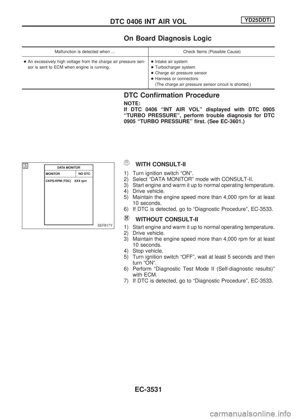
WITH CONSULT-II
1) Turn ignition switch ªONº.
2) Select ªDATA MONITORº mode with CONSULT-II.
3) Start engine and warm it up to normal operating temperature.
4) Drive vehicle.
5) Maintain the engine speed more than 4,000 rpm for at least
10 seconds.
6) If DTC is detected, go to ªDiagnostic Procedureº, EC-3533.
WITHOUT CONSULT-II
1) Start engine and warm it up to normal operating temperature.
2) Drive vehicle.
3) Maintain the engine speed more than 4,000 rpm for at least
10 seconds.
4) Stop vehicle.
5) Turn ignition switch ªOFFº, wait at least 5 seconds and then
turn ªONº.
6) Perform ªDiagnostic Test Mode II (Self-diagnostic results)º
with ECM.
7) If DTC is detected, go to ªDiagnostic Procedureº, EC-3533.SEF817Y
DTC 0406 INT AIR VOLYD25DDTi
EC-3531
Page 597 of 1306

DTC Confirmation Procedure
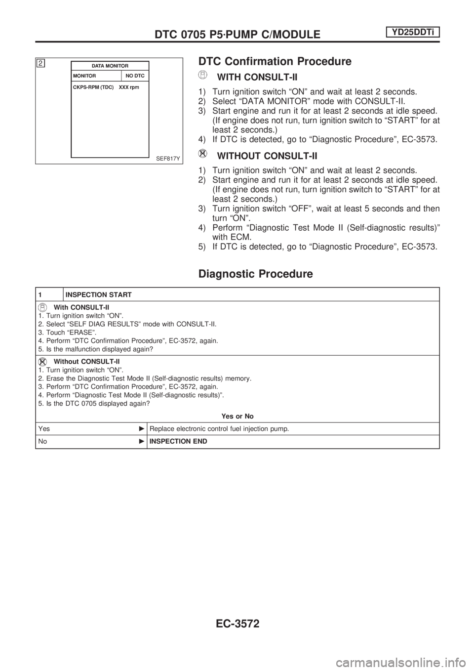
WITH CONSULT-II
1) Turn ignition switch ªONº and wait at least 2 seconds.
2) Select ªDATA MONITORº mode with CONSULT-II.
3) Start engine and run it for at least 2 seconds at idle speed.
(If engine does not run, turn ignition switch to ªSTARTº for at
least 2 seconds.)
4) If DTC is detected, go to ªDiagnostic Procedureº, EC-3573.
WITHOUT CONSULT-II
1) Turn ignition switch ªONº and wait at least 2 seconds.
2) Start engine and run it for at least 2 seconds at idle speed.
(If engine does not run, turn ignition switch to ªSTARTº for at
least 2 seconds.)
3) Turn ignition switch ªOFFº, wait at least 5 seconds and then
turn ªONº.
4) Perform ªDiagnostic Test Mode II (Self-diagnostic results)º
with ECM.
5) If DTC is detected, go to ªDiagnostic Procedureº, EC-3573.
Diagnostic Procedure
1 INSPECTION START
With CONSULT-II
1. Turn ignition switch ªONº.
2. Select ªSELF DIAG RESULTSº mode with CONSULT-II.
3. Touch ªERASEº.
4. Perform ªDTC Confirmation Procedureº, EC-3572, again.
5. Is the malfunction displayed again?
Without CONSULT-II
1. Turn ignition switch ªONº.
2. Erase the Diagnostic Test Mode II (Self-diagnostic results) memory.
3. Perform ªDTC Confirmation Procedureº, EC-3572, again.
4. Perform ªDiagnostic Test Mode II (Self-diagnostic results)º.
5. Is the DTC 0705 displayed again?
Yes or No
YescReplace electronic control fuel injection pump.
NocINSPECTION END
SEF817Y
DTC 0705 P5zPUMP C/MODULEYD25DDTi
EC-3572
Page 607 of 1306
Diagnostic Procedure
1 INSPECTION START
With CONSULT-II
1. Turn ignition switch ªONº.
2. Select ªSELF DIAG RESULTSº mode with CONSULT-II.
3. Touch ªERASEº.
4. Perform ªDTC Confirmation Procedureº, EC-3581, again.
5. Is the malfunction displayed again?
Without CONSULT-II
1. Turn ignition switch ªONº.
2. Erase the Diagnostic Test Mode II (Self-diagnostic results) memory.
3. Perform ªDTC Confirmation Procedureº, EC-3581, again.
4. Perform ªDiagnostic Test Mode II (Self-diagnostic results)º.
5. Is the DTC 0802 displayed again?
Yes or No
YescGO TO 2.
NocINSPECTION END
2 REPLACE ECM
1. Replace ECM.
2. Perform initialization of NATS system and registration of all NATS ignition key IDs. Refer to EC-3429. (Models with NATS)
3. Perform ªAccelerator Position Sensor Idle Position Learningº of ªBASIC SERVICE PROCEDUREº. Refer to EC-3427.
cINSPECTION END
DTC 0802 ECM 10YD25DDTi
EC-3582
Page 609 of 1306
Diagnostic Procedure
1 INSPECTION START
With CONSULT-II
1. Turn ignition switch ªONº.
2. Select ªSELF DIAG RESULTSº mode with CONSULT-II.
3. Touch ªERASEº.
4. Perform ªDTC Confirmation Procedureº, EC-3583, again.
5. Is the malfunction displayed again?
Without CONSULT-II
1. Turn ignition switch ªONº.
2. Erase the Diagnostic Test Mode II (Self-diagnostic results) memory.
3. Perform ªDTC Confirmation Procedureº, EC-3583, again.
4. Perform ªDiagnostic Test Mode II (Self-diagnostic results)º.
5. Is the DTC 0802 displayed again?
Yes or No
YescGO TO 2.
NocINSPECTION END
2 REPLACE ECM
1. Replace ECM.
2. Perform initialization of NATS system and registration of all NATS ignition key IDs. Refer to EC-3429. (Models with NATS)
3. Perform ªAccelerator Position Sensor Idle Position Learningº of ªBASIC SERVICE PROCEDUREº. Refer to EC-3427.
cINSPECTION END
DTC 0804 ECM 11YD25DDTi
EC-3584
Page 624 of 1306
Diagnostic Procedure
1 INSPECTION START
With CONSULT-II
1. Turn ignition switch ªONº.
2. Select ªSELF DIAG RESULTSº mode with CONSULT-II.
3. Touch ªERASEº.
4. Perform ªDTC Confirmation Procedureº, EC-3598, again.
5. Is the malfunction displayed again?
Without CONSULT-II
1. Turn ignition switch ªONº.
2. Erase the Diagnostic Test Mode II (Self-diagnostic results) memory.
3. Perform ªDTC Confirmation Procedureº, EC-3598, again.
4. Perform ªDiagnostic Test Mode II (Self-diagnostic results)º.
5. Is the DTC 0903 displayed again?
Yes or No
YescGO TO 2.
NocINSPECTION END
2 REPLACE ECM
1. Replace ECM.
2. Perform intialization of NATS system and registration of all NATS ignition key IDs. Refer to EC-3429. (Models with NATS)
3. Perform ªAccelerator Position Sensor Idle Position Learningº of ªBASIC SERVICE PROCEDUREº. Refer to EC-3427.
cINSPECTION END
DTC 0903 ECM 15YD25DDTi
EC-3599
Page 731 of 1306
System Description
UNIFIED CONTROL METER
+Speedometer, odo/trip meter, tachometer, fuel gauge and water temperature gauge are controlled totally
by control unit.
+Digital meter is adopted for odo/trip meter.*
*The record of the odo meter is kept even if the battery cable is disconnected. The record of the trip meter
is erased when the battery cable is disconnected.
+Odo/trip meter segment can be checked in diagnosis mode.
+Meter/gauge can be checked in diagnosis mode.
HOW TO CHANGE THE DISPLAY FOR ODO/TRIP METER
Note:
Turn ignition switch to the ªONº position to operate odo/trip meter.
SEL253V
METER AND GAUGES
EL-3056
Page 824 of 1306

Trouble Diagnoses
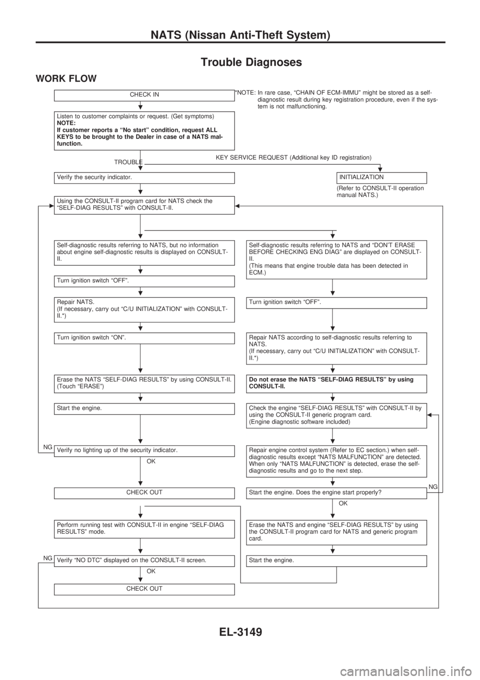
WORK FLOW
CHECK IN*NOTE: In rare case, ªCHAIN OF ECM-IMMUº might be stored as a self-
diagnostic result during key registration procedure, even if the sys-
tem is not malfunctioning.
Listen to customer complaints or request. (Get symptoms)
NOTE:
If customer reports a ªNo startº condition, request ALL
KEYS to be brought to the Dealer in case of a NATS mal-
function.
TROUBLEKEY SERVICE REQUEST (Additional key ID registration).Verify the security indicator.INITIALIZATION
(Refer to CONSULT-II operation
manual NATS.)
cUsing the CONSULT-II program card for NATS check the
ªSELF-DIAG RESULTSº with CONSULT-II.b
Self-diagnostic results referring to NATS, but no information
about engine self-diagnostic results is displayed on CONSULT-
II.Self-diagnostic results referring to NATS and ªDON'T ERASE
BEFORE CHECKING ENG DIAGº are displayed on CONSULT-
II.
(This means that engine trouble data has been detected in
ECM.)
Turn ignition switch ªOFFº.
Repair NATS.
(If necessary, carry out ªC/U INITIALIZATIONº with CONSULT-
II.*)Turn ignition switch ªOFFº.
Turn ignition switch ªONº.Repair NATS according to self-diagnostic results referring to
NATS.
(If necessary, carry out ªC/U INITIALIZATIONº with CONSULT-
II.*)
Erase the NATS ªSELF-DIAG RESULTSº by using CONSULT-II.
(Touch ªERASEº)Do not erase the NATS ªSELF-DIAG RESULTSº by using
CONSULT-II.
Start the engine.Check the engine ªSELF-DIAG RESULTSº with CONSULT-II by
using the CONSULT-II generic program card.
(Engine diagnostic software included)b
NGVerify no lighting up of the security indicator.
OKRepair engine control system (Refer to EC section.) when self-
diagnostic results except ªNATS MALFUNCTIONº are detected.
When only ªNATS MALFUNCTIONº is detected, erase the self-
diagnostic results and go to the next step.
CHECK OUTStart the engine. Does the engine start properly?
OKNG
Perform running test with CONSULT-II in engine ªSELF-DIAG
RESULTSº mode.Erase the NATS and engine ªSELF-DIAG RESULTSº by using
the CONSULT-II program card for NATS and generic program
card.
NGVerify ªNO DTCº displayed on the CONSULT-II screen.
OKStart the engine.
CHECK OUT
.
.
.
..
.
..
..
..
..
..
..
..
..
.
NATS (Nissan Anti-Theft System)
EL-3149
Page 825 of 1306

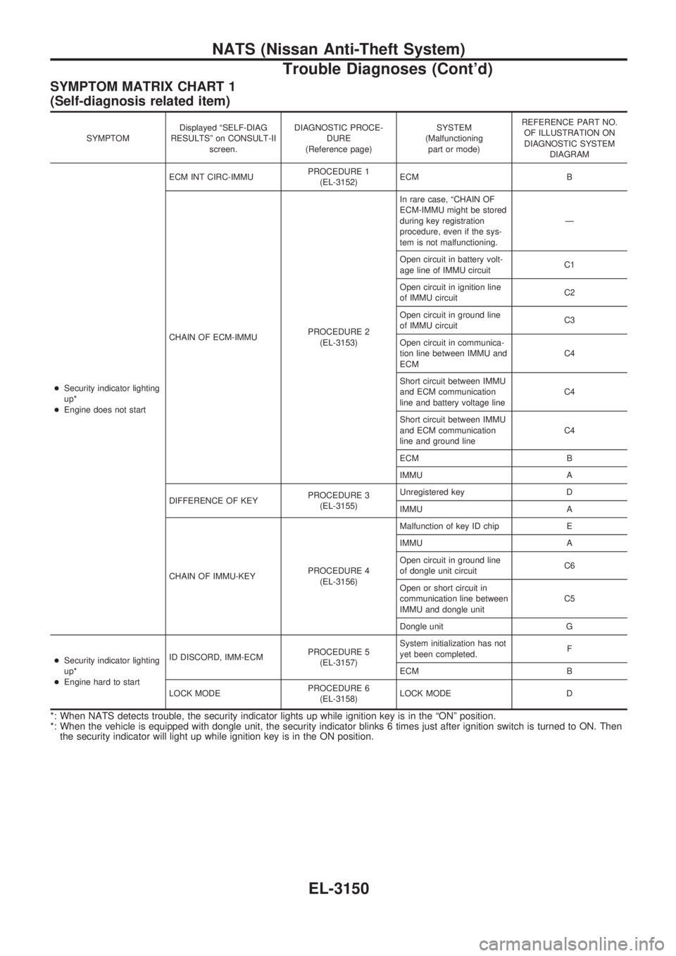
SYMPTOM MATRIX CHART 1
(Self-diagnosis related item)
SYMPTOMDisplayed ªSELF-DIAG
RESULTSº on CONSULT-II
screen.DIAGNOSTIC PROCE-
DURE
(Reference page)SYSTEM
(Malfunctioning
part or mode)REFERENCE PART NO.
OF ILLUSTRATION ON
DIAGNOSTIC SYSTEM
DIAGRAM
+Security indicator lighting
up*
+Engine does not startECM INT CIRC-IMMUPROCEDURE 1
(EL-3152)ECM B
CHAIN OF ECM-IMMUPROCEDURE 2
(EL-3153)In rare case, ªCHAIN OF
ECM-IMMU might be stored
during key registration
procedure, even if the sys-
tem is not malfunctioning.Ð
Open circuit in battery volt-
age line of IMMU circuitC1
Open circuit in ignition line
of IMMU circuitC2
Open circuit in ground line
of IMMU circuitC3
Open circuit in communica-
tion line between IMMU and
ECMC4
Short circuit between IMMU
and ECM communication
line and battery voltage lineC4
Short circuit between IMMU
and ECM communication
line and ground lineC4
ECM B
IMMU A
DIFFERENCE OF KEYPROCEDURE 3
(EL-3155)Unregistered key D
IMMU A
CHAIN OF IMMU-KEYPROCEDURE 4
(EL-3156)Malfunction of key ID chip E
IMMU A
Open circuit in ground line
of dongle unit circuitC6
Open or short circuit in
communication line between
IMMU and dongle unitC5
Dongle unit G
+Security indicator lighting
up*
+Engine hard to startID DISCORD, IMM-ECMPROCEDURE 5
(EL-3157)System initialization has not
yet been completed.F
ECM B
LOCK MODEPROCEDURE 6
(EL-3158)LOCK MODE D
*: When NATS detects trouble, the security indicator lights up while ignition key is in the ªONº position.
*: When the vehicle is equipped with dongle unit, the security indicator blinks 6 times just after ignition switch is turned to ON. Then
the security indicator will light up while ignition key is in the ON position.
NATS (Nissan Anti-Theft System)
Trouble Diagnoses (Cont'd)
EL-3150