Page 1092 of 1306
DIAGNOSTIC PROCEDURE 2 (with CONSULT-II)
Inspecting SRS malfunctioning parts by using CONSULT-II
Ð Diagnosis mode
1. Turn ignition switch ªOFFº.
2. Connect CONSULT-II to data link connector.
3. Turn ignition switch ªONº.
4. Touch ªSTARTº.
5. Touch ªAIR BAGº.
6. Touch ªSELF-DIAG [CURRENT]º.
7. Diagnostic codes are displayed on ªSELF-DIAG [CUR-
RENT]º.
SRS733
SRS695
SRS771
SRS697
SHIA0203E
TROUBLE DIAGNOSES Ð Supplemental Restraint System (SRS)
Self-diagnosis (Cont'd)
RS-3021
Page 1104 of 1306
5. Touch ªAIR BAGº.
6. Touch ªSELF-DIAG [PAST]º.
7. If diagnostic codes are displayed on ªSELF-DIAG [PAST]º,
go to step 10.
If no malfunction is detected on ªSELF-DIAG [PAST]º, touch
ªBACKº and go back to ªSELECT DIAG MODEº.
8. Touch ªTROUBLE DIAG RECORDº.
NOTE:
With ªTROUBLE DIAG RECORDº, diagnosis results previ-
ously erased by a reset operation can be displayed.
SRS771
SRS697
SHIA0181E
SRS702
SRS697
TROUBLE DIAGNOSES Ð Supplemental Restraint System (SRS)
Self-diagnosis (Cont'd)
RS-3033
Page 1105 of 1306

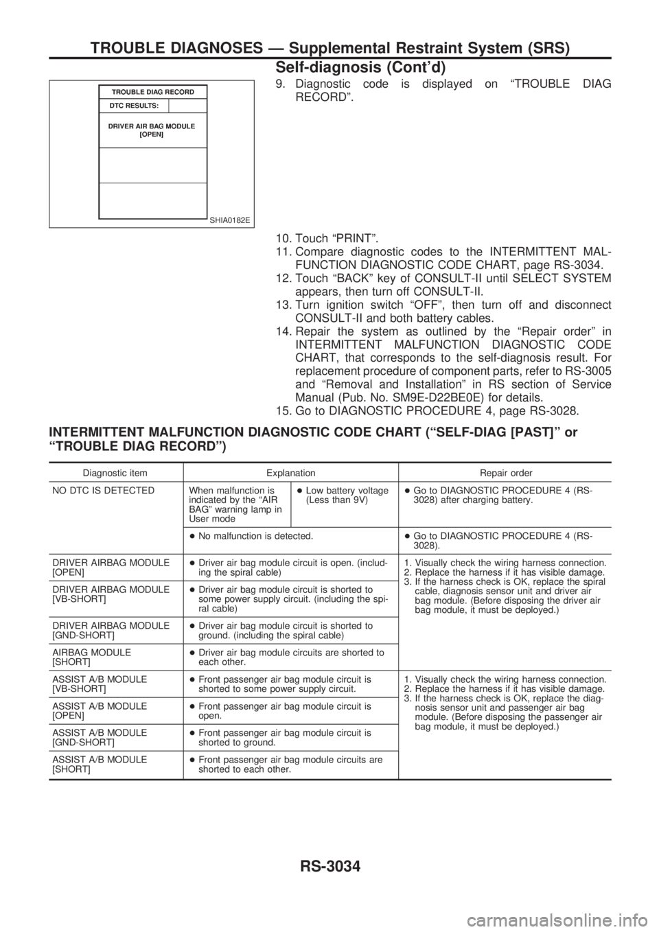
9. Diagnostic code is displayed on ªTROUBLE DIAG
RECORDº.
10. Touch ªPRINTº.
11. Compare diagnostic codes to the INTERMITTENT MAL-
FUNCTION DIAGNOSTIC CODE CHART, page RS-3034.
12. Touch ªBACKº key of CONSULT-II until SELECT SYSTEM
appears, then turn off CONSULT-II.
13. Turn ignition switch ªOFFº, then turn off and disconnect
CONSULT-II and both battery cables.
14. Repair the system as outlined by the ªRepair orderº in
INTERMITTENT MALFUNCTION DIAGNOSTIC CODE
CHART, that corresponds to the self-diagnosis result. For
replacement procedure of component parts, refer to RS-3005
and ªRemoval and Installationº in RS section of Service
Manual (Pub. No. SM9E-D22BE0E) for details.
15. Go to DIAGNOSTIC PROCEDURE 4, page RS-3028.
INTERMITTENT MALFUNCTION DIAGNOSTIC CODE CHART (ªSELF-DIAG [PAST]º or
ªTROUBLE DIAG RECORDº)
Diagnostic item Explanation Repair order
NO DTC IS DETECTED When malfunction is
indicated by the ªAIR
BAGº warning lamp in
User mode+Low battery voltage
(Less than 9V)+Go to DIAGNOSTIC PROCEDURE 4 (RS-
3028) after charging battery.
+No malfunction is detected.+Go to DIAGNOSTIC PROCEDURE 4 (RS-
3028).
DRIVER AIRBAG MODULE
[OPEN]+Driver air bag module circuit is open. (includ-
ing the spiral cable)1. Visually check the wiring harness connection.
2. Replace the harness if it has visible damage.
3. If the harness check is OK, replace the spiral
cable, diagnosis sensor unit and driver air
bag module. (Before disposing the driver air
bag module, it must be deployed.) DRIVER AIRBAG MODULE
[VB-SHORT]+Driver air bag module circuit is shorted to
some power supply circuit. (including the spi-
ral cable)
DRIVER AIRBAG MODULE
[GND-SHORT]+Driver air bag module circuit is shorted to
ground. (including the spiral cable)
AIRBAG MODULE
[SHORT]+Driver air bag module circuits are shorted to
each other.
ASSIST A/B MODULE
[VB-SHORT]+Front passenger air bag module circuit is
shorted to some power supply circuit.1. Visually check the wiring harness connection.
2. Replace the harness if it has visible damage.
3. If the harness check is OK, replace the diag-
nosis sensor unit and passenger air bag
module. (Before disposing the passenger air
bag module, it must be deployed.) ASSIST A/B MODULE
[OPEN]+Front passenger air bag module circuit is
open.
ASSIST A/B MODULE
[GND-SHORT]+Front passenger air bag module circuit is
shorted to ground.
ASSIST A/B MODULE
[SHORT]+Front passenger air bag module circuits are
shorted to each other.
SHIA0182E
TROUBLE DIAGNOSES Ð Supplemental Restraint System (SRS)
Self-diagnosis (Cont'd)
RS-3034
Page 1107 of 1306

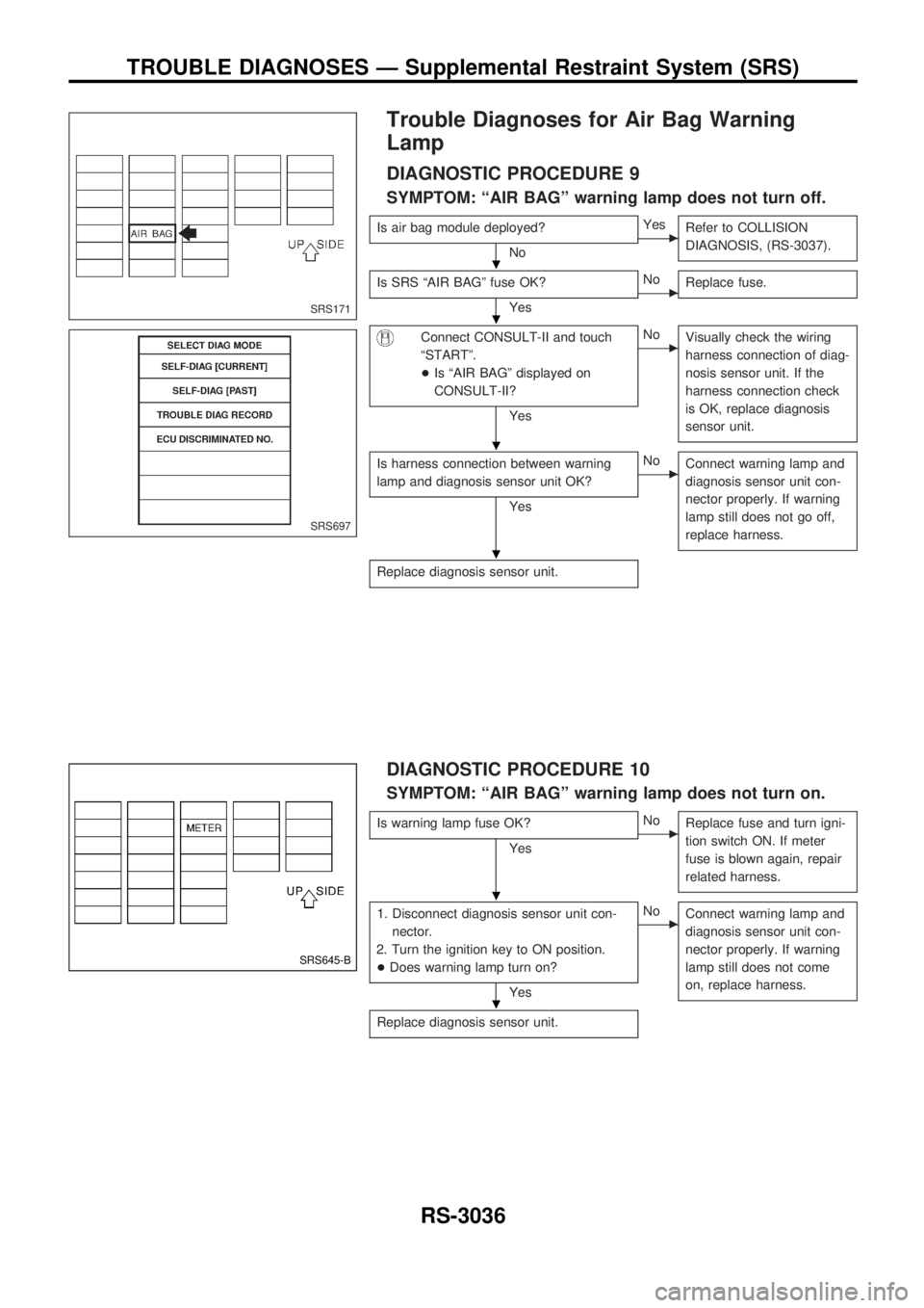
Trouble Diagnoses for Air Bag Warning
Lamp
DIAGNOSTIC PROCEDURE 9
SYMPTOM: ªAIR BAGº warning lamp does not turn off.
Is air bag module deployed?
NocYes
Refer to COLLISION
DIAGNOSIS, (RS-3037).
Is SRS ªAIR BAGº fuse OK?
YescNo
Replace fuse.
Connect CONSULT-II and touch
ªSTARTº.
+Is ªAIR BAGº displayed on
CONSULT-II?
Yes
cNo
Visually check the wiring
harness connection of diag-
nosis sensor unit. If the
harness connection check
is OK, replace diagnosis
sensor unit.
Is harness connection between warning
lamp and diagnosis sensor unit OK?
Yes
cNo
Connect warning lamp and
diagnosis sensor unit con-
nector properly. If warning
lamp still does not go off,
replace harness.
Replace diagnosis sensor unit.
DIAGNOSTIC PROCEDURE 10
SYMPTOM: ªAIR BAGº warning lamp does not turn on.
Is warning lamp fuse OK?
YescNo
Replace fuse and turn igni-
tion switch ON. If meter
fuse is blown again, repair
related harness.
1. Disconnect diagnosis sensor unit con-
nector.
2. Turn the ignition key to ON position.
+Does warning lamp turn on?
Yes
cNo
Connect warning lamp and
diagnosis sensor unit con-
nector properly. If warning
lamp still does not come
on, replace harness.
Replace diagnosis sensor unit.
SRS171
SRS697
SRS645-B
.
.
.
.
.
.
TROUBLE DIAGNOSES Ð Supplemental Restraint System (SRS)
RS-3036
Page 1167 of 1306
System Description
UNIFIED CONTROL METER
+Speedometer, odo/trip meter, tachometer, fuel gauge and water temperature gauge are controlled totally
by control unit.
+Digital meter is adopted for odo/trip meter.*
*The record of the odo meter is kept even if the battery cable is disconnected. The record of the trip meter
is erased when the battery cable is disconnected.
+Odo/trip meter segment can be checked in diagnosis mode.
+Meter/gauge can be checked in diagnosis mode.
HOW TO CHANGE THE DISPLAY FOR ODO/TRIP METER
Note:
Turn ignition switch to the ªONº position to operate odo/trip meter.
SEL253V
METER AND GAUGES
EL-3056
Page 1260 of 1306

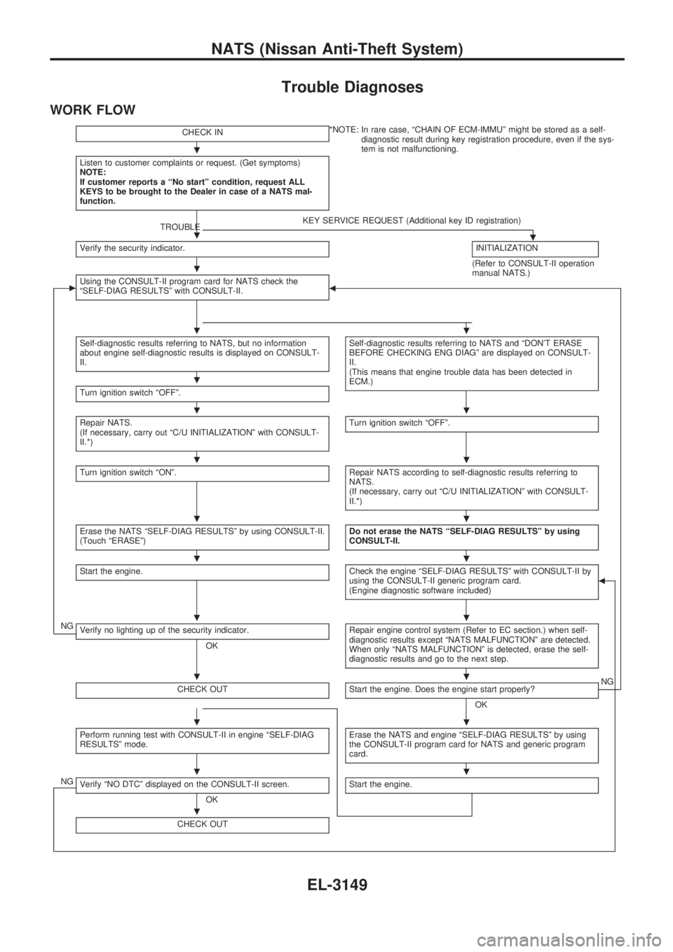
Trouble Diagnoses
WORK FLOW
CHECK IN*NOTE: In rare case, ªCHAIN OF ECM-IMMUº might be stored as a self-
diagnostic result during key registration procedure, even if the sys-
tem is not malfunctioning.
Listen to customer complaints or request. (Get symptoms)
NOTE:
If customer reports a ªNo startº condition, request ALL
KEYS to be brought to the Dealer in case of a NATS mal-
function.
TROUBLEKEY SERVICE REQUEST (Additional key ID registration).Verify the security indicator.INITIALIZATION
(Refer to CONSULT-II operation
manual NATS.)
cUsing the CONSULT-II program card for NATS check the
ªSELF-DIAG RESULTSº with CONSULT-II.b
Self-diagnostic results referring to NATS, but no information
about engine self-diagnostic results is displayed on CONSULT-
II.Self-diagnostic results referring to NATS and ªDON'T ERASE
BEFORE CHECKING ENG DIAGº are displayed on CONSULT-
II.
(This means that engine trouble data has been detected in
ECM.)
Turn ignition switch ªOFFº.
Repair NATS.
(If necessary, carry out ªC/U INITIALIZATIONº with CONSULT-
II.*)Turn ignition switch ªOFFº.
Turn ignition switch ªONº.Repair NATS according to self-diagnostic results referring to
NATS.
(If necessary, carry out ªC/U INITIALIZATIONº with CONSULT-
II.*)
Erase the NATS ªSELF-DIAG RESULTSº by using CONSULT-II.
(Touch ªERASEº)Do not erase the NATS ªSELF-DIAG RESULTSº by using
CONSULT-II.
Start the engine.Check the engine ªSELF-DIAG RESULTSº with CONSULT-II by
using the CONSULT-II generic program card.
(Engine diagnostic software included)b
NGVerify no lighting up of the security indicator.
OKRepair engine control system (Refer to EC section.) when self-
diagnostic results except ªNATS MALFUNCTIONº are detected.
When only ªNATS MALFUNCTIONº is detected, erase the self-
diagnostic results and go to the next step.
CHECK OUTStart the engine. Does the engine start properly?
OKNG
Perform running test with CONSULT-II in engine ªSELF-DIAG
RESULTSº mode.Erase the NATS and engine ªSELF-DIAG RESULTSº by using
the CONSULT-II program card for NATS and generic program
card.
NGVerify ªNO DTCº displayed on the CONSULT-II screen.
OKStart the engine.
CHECK OUT
.
.
.
..
.
..
..
..
..
..
..
..
..
.
NATS (Nissan Anti-Theft System)
EL-3149
Page 1261 of 1306

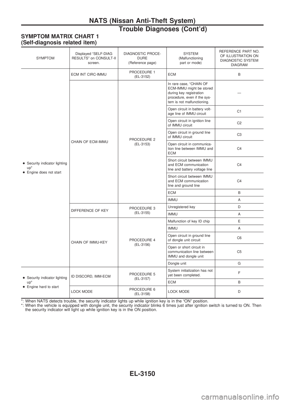
SYMPTOM MATRIX CHART 1
(Self-diagnosis related item)
SYMPTOMDisplayed ªSELF-DIAG
RESULTSº on CONSULT-II
screen.DIAGNOSTIC PROCE-
DURE
(Reference page)SYSTEM
(Malfunctioning
part or mode)REFERENCE PART NO.
OF ILLUSTRATION ON
DIAGNOSTIC SYSTEM
DIAGRAM
+Security indicator lighting
up*
+Engine does not startECM INT CIRC-IMMUPROCEDURE 1
(EL-3152)ECM B
CHAIN OF ECM-IMMUPROCEDURE 2
(EL-3153)In rare case, ªCHAIN OF
ECM-IMMU might be stored
during key registration
procedure, even if the sys-
tem is not malfunctioning.Ð
Open circuit in battery volt-
age line of IMMU circuitC1
Open circuit in ignition line
of IMMU circuitC2
Open circuit in ground line
of IMMU circuitC3
Open circuit in communica-
tion line between IMMU and
ECMC4
Short circuit between IMMU
and ECM communication
line and battery voltage lineC4
Short circuit between IMMU
and ECM communication
line and ground lineC4
ECM B
IMMU A
DIFFERENCE OF KEYPROCEDURE 3
(EL-3155)Unregistered key D
IMMU A
CHAIN OF IMMU-KEYPROCEDURE 4
(EL-3156)Malfunction of key ID chip E
IMMU A
Open circuit in ground line
of dongle unit circuitC6
Open or short circuit in
communication line between
IMMU and dongle unitC5
Dongle unit G
+Security indicator lighting
up*
+Engine hard to startID DISCORD, IMM-ECMPROCEDURE 5
(EL-3157)System initialization has not
yet been completed.F
ECM B
LOCK MODEPROCEDURE 6
(EL-3158)LOCK MODE D
*: When NATS detects trouble, the security indicator lights up while ignition key is in the ªONº position.
*: When the vehicle is equipped with dongle unit, the security indicator blinks 6 times just after ignition switch is turned to ON. Then
the security indicator will light up while ignition key is in the ON position.
NATS (Nissan Anti-Theft System)
Trouble Diagnoses (Cont'd)
EL-3150
Page 1263 of 1306
DIAGNOSTIC PROCEDURE 1
Self-diagnostic results:
ªECM INT CIRC-IMMUº displayed on CONSULT-II screen
Confirm SELF-DIAGNOSTIC RESULTS ªECM INT CIRC-IMMUº dis-
played on CONSULT-II screen.
Ref. part No. B.
Replace ECM.
Perform initialization with CONSULT-II.
For the operation of initialization, refer to ªCONSULT-II operation
manual NATSº.
SEL152X.
.
NATS (Nissan Anti-Theft System)
Trouble Diagnoses (Cont'd)
EL-3152