Page 827 of 1306
DIAGNOSTIC PROCEDURE 1
Self-diagnostic results:
ªECM INT CIRC-IMMUº displayed on CONSULT-II screen
Confirm SELF-DIAGNOSTIC RESULTS ªECM INT CIRC-IMMUº dis-
played on CONSULT-II screen.
Ref. part No. B.
Replace ECM.
Perform initialization with CONSULT-II.
For the operation of initialization, refer to ªCONSULT-II operation
manual NATSº.
SEL152X.
.
NATS (Nissan Anti-Theft System)
Trouble Diagnoses (Cont'd)
EL-3152
Page 828 of 1306

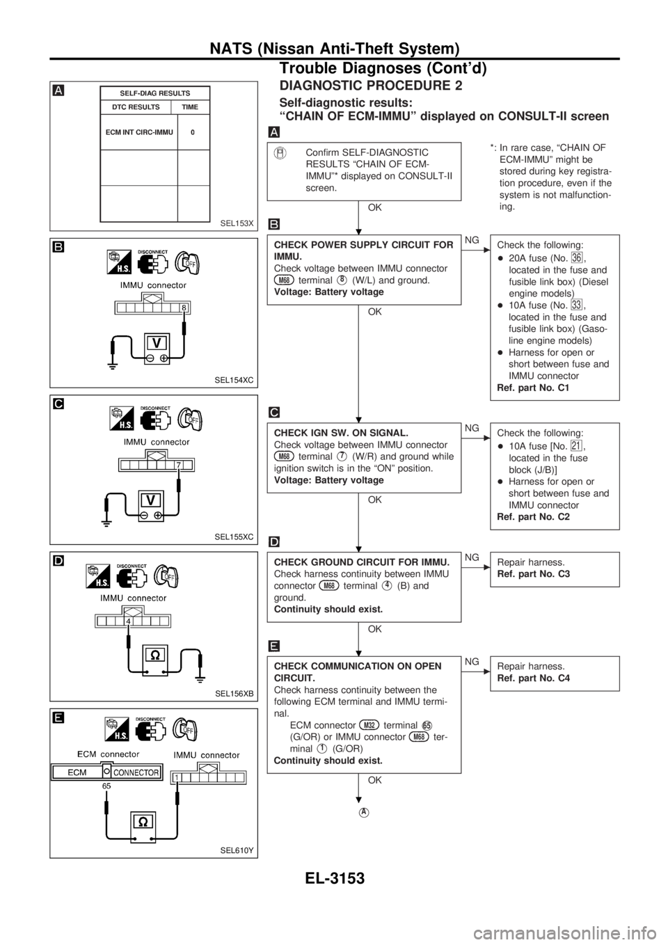
DIAGNOSTIC PROCEDURE 2
Self-diagnostic results:
ªCHAIN OF ECM-IMMUº displayed on CONSULT-II screen
Confirm SELF-DIAGNOSTIC
RESULTS ªCHAIN OF ECM-
IMMUº* displayed on CONSULT-II
screen.
OK*: In rare case, ªCHAIN OF
ECM-IMMUº might be
stored during key registra-
tion procedure, even if the
system is not malfunction-
ing.
CHECK POWER SUPPLY CIRCUIT FOR
IMMU.
Check voltage between IMMU connector
M68terminalV8(W/L) and ground.
Voltage: Battery voltage
OK
cNG
Check the following:
+20A fuse (No.
36,
located in the fuse and
fusible link box) (Diesel
engine models)
+10A fuse (No.
33,
located in the fuse and
fusible link box) (Gaso-
line engine models)
+Harness for open or
short between fuse and
IMMU connector
Ref. part No. C1
CHECK IGN SW. ON SIGNAL.
Check voltage between IMMU connector
M68terminalV7(W/R) and ground while
ignition switch is in the ªONº position.
Voltage: Battery voltage
OK
cNG
Check the following:
+10A fuse [No.
21,
located in the fuse
block (J/B)]
+Harness for open or
short between fuse and
IMMU connector
Ref. part No. C2
CHECK GROUND CIRCUIT FOR IMMU.
Check harness continuity between IMMU
connector
M68terminalV4(B) and
ground.
Continuity should exist.
OK
cNG
Repair harness.
Ref. part No. C3
CHECK COMMUNICATION ON OPEN
CIRCUIT.
Check harness continuity between the
following ECM terminal and IMMU termi-
nal.
ECM connector
M32terminalV65
(G/OR) or IMMU connectorM68ter-
minal
V1(G/OR)
Continuity should exist.
OK
cNG
Repair harness.
Ref. part No. C4
VA
SEL153X
SEL154XC
SEL155XC
SEL156XB
SEL610Y
.
.
.
.
.
NATS (Nissan Anti-Theft System)
Trouble Diagnoses (Cont'd)
EL-3153
Page 830 of 1306
DIAGNOSTIC PROCEDURE 3
Self-diagnostic results:
ªDIFFERENCE OF KEYº displayed on CONSULT-II screen
Confirm SELF-DIAGNOSTIC
RESULTS ªDIFFERENCE OF
KEYº displayed on CONSULT-II
screen.
OK
PERFORM INITIALIZATION.
Perform initialization with CONSULT-II.
Re-register all NATS ignition key IDs.
For the initialization procedure, refer to
ªCONSULT-II operation manual NATSº.
Initialization
completedInitialization
with CON-
SULT-II
incomplete or
failed
c
+IMMU is mal-
functioning.
1. Replace
IMMU.
Ref. part No.
A
2. Perform initial-
ization with
CONSULT-II.
For the initial-
ization
procedure,
refer to ªCON-
SULT-II opera-
tion manual
NATSº.
Start engine.
END.
(The ignition key was unregistered.)
Ref. part No. D
SEL163X
SEL566W
.
.
.
NATS (Nissan Anti-Theft System)
Trouble Diagnoses (Cont'd)
EL-3155
Page 831 of 1306

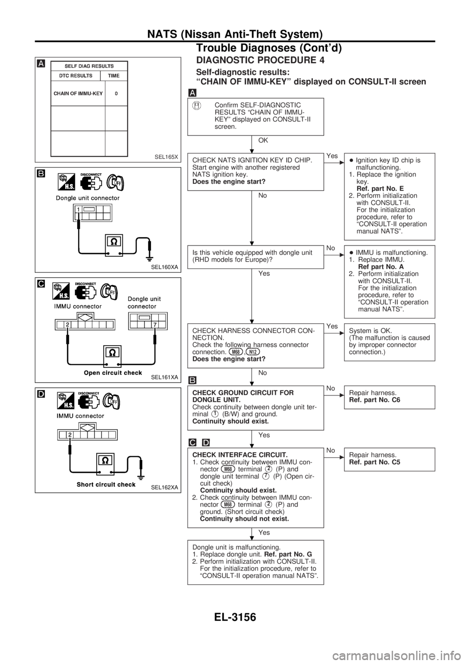
DIAGNOSTIC PROCEDURE 4
Self-diagnostic results:
ªCHAIN OF IMMU-KEYº displayed on CONSULT-II screen
Confirm SELF-DIAGNOSTIC
RESULTS ªCHAIN OF IMMU-
KEYº displayed on CONSULT-II
screen.
OK
CHECK NATS IGNITION KEY ID CHIP.
Start engine with another registered
NATS ignition key.
Does the engine start?
No
cYes
+Ignition key ID chip is
malfunctioning.
1. Replace the ignition
key.
Ref. part No. E
2. Perform initialization
with CONSULT-II.
For the initialization
procedure, refer to
ªCONSULT-II operation
manual NATSº.
Is this vehicle equipped with dongle unit
(RHD models for Europe)?
Yes
cNo
+IMMU is malfunctioning.
1. Replace IMMU.
Ref part No. A
2. Perform initialization
with CONSULT-II.
For the initialization
procedure, refer to
ªCONSULT-II operation
manual NATSº.
CHECK HARNESS CONNECTOR CON-
NECTION.
Check the following harness connector
connection.
M68,N12Does the engine start?
No
cYes
System is OK.
(The malfunction is caused
by improper connector
connection.)
CHECK GROUND CIRCUIT FOR
DONGLE UNIT.
Check continuity between dongle unit ter-
minal
V1(B/W) and ground.
Continuity should exist.
Yes
cNo
Repair harness.
Ref. part No. C6
CHECK INTERFACE CIRCUIT.
1. Check continuity between IMMU con-
nector
M68terminalV2(P) and
dongle unit terminalV7(P) (Open cir-
cuit check)
Continuity should exist.
2. Check continuity between IMMU con-
nector
M68terminalV2(P) and
ground. (Short circuit check)
Continuity should not exist.
Yes
cNo
Repair harness.
Ref. part No. C5
Dongle unit is malfunctioning.
1. Replace dongle unit.Ref. part No. G
2. Perform initialization with CONSULT-II.
For the initialization procedure, refer to
ªCONSULT-II operation manual NATSº.
SEL165X
SEL160XA
SEL161XA
SEL162XA
.
.
.
.
.
.
NATS (Nissan Anti-Theft System)
Trouble Diagnoses (Cont'd)
EL-3156
Page 832 of 1306
DIAGNOSTIC PROCEDURE 5
Self-diagnostic results:
ªID DISCORD, IMM-ECMº displayed on CONSULT-II screen
Confirm SELF-DIAGNOSTIC
RESULTS ªID DISCORD, IMM-
ECM*º displayed on CONSULT-II
screen.* ªID DISCORD, IMM-ECMº:
Registered ID of IMMU is
in discord with that of
ECM.
PERFORM INITIALIZATION.
Perform initialization with CONSULT-II.
Re-register all NATS ignition key IDs.
For the initialization procedure, refer to
ªCONSULT-II operation manual NATSº.
Initialization
completedInitialization
with CON-
SULT-II
incomplete or
failed
c
+ECM is mal-
functioning.
1. Replace ECM.
Ref. part No.
B
2. Perform initial-
ization with
CONSULT-II.
For the initial-
ization
procedure,
refer to ªCON-
SULT-II opera-
tion manual
NATSº.
Start engine. (END)
(System initialization was not completed.
Ref. part No. F)
SEL166X
SEL566W
.
.
NATS (Nissan Anti-Theft System)
Trouble Diagnoses (Cont'd)
EL-3157
Page 833 of 1306

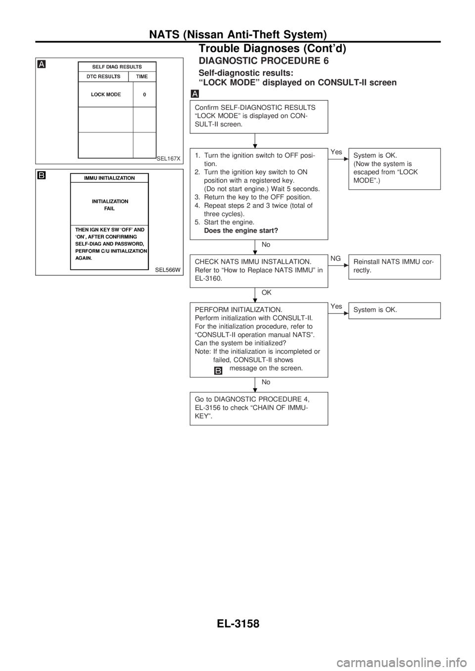
DIAGNOSTIC PROCEDURE 6
Self-diagnostic results:
ªLOCK MODEº displayed on CONSULT-II screen
Confirm SELF-DIAGNOSTIC RESULTS
ªLOCK MODEº is displayed on CON-
SULT-II screen.
1. Turn the ignition switch to OFF posi-
tion.
2. Turn the ignition key switch to ON
position with a registered key.
(Do not start engine.) Wait 5 seconds.
3. Return the key to the OFF position.
4. Repeat steps 2 and 3 twice (total of
three cycles).
5. Start the engine.
Does the engine start?
No
cYes
System is OK.
(Now the system is
escaped from ªLOCK
MODEº.)
CHECK NATS IMMU INSTALLATION.
Refer to ªHow to Replace NATS IMMUº in
EL-3160.
OK
cNG
Reinstall NATS IMMU cor-
rectly.
PERFORM INITIALIZATION.
Perform initialization with CONSULT-II.
For the initialization procedure, refer to
ªCONSULT-II operation manual NATSº.
Can the system be initialized?
Note: If the initialization is incompleted or
failed, CONSULT-II shows
message on the screen.
No
cYes
System is OK.
Go to DIAGNOSTIC PROCEDURE 4,
EL-3156 to check ªCHAIN OF IMMU-
KEYº.
SEL167X
SEL566W
.
.
.
.
NATS (Nissan Anti-Theft System)
Trouble Diagnoses (Cont'd)
EL-3158
Page 1085 of 1306

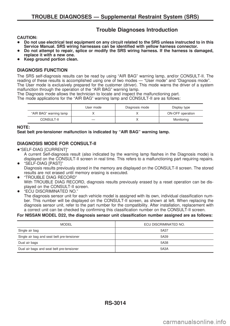
Trouble Diagnoses Introduction
CAUTION:
+Do not use electrical test equipment on any circuit related to the SRS unless instructed to in this
Service Manual. SRS wiring harnesses can be identified with yellow harness connector.
+Do not attempt to repair, splice or modify the SRS wiring harness. If the harness is damaged,
replace it with a new one.
+Keep ground portion clean.
DIAGNOSIS FUNCTION
The SRS self-diagnosis results can be read by using ªAIR BAGº warning lamp, and/or CONSULT-II. The
reading of these results is accomplished using one of two modes Ð ªUser modeº and ªDiagnosis modeº.
The User mode is exclusively prepared for the customer (driver). This mode warns the driver of a system
malfunction through the operation of the ªAIR BAGº warning lamp.
The Diagnosis mode allows the technician to locate and inspect the malfunctioning part.
The mode applications for the ªAIR BAGº warning lamp and CONSULT-II are as follows:
User mode Diagnosis mode Display type
ªAIR BAGº warning lamp X X ON-OFF operation
CONSULT-II Ð X Monitoring
NOTE:
Seat belt pre-tensioner malfunction is indicated by ªAIR BAGº warning lamp.
DIAGNOSIS MODE FOR CONSULT-II
+ªSELF-DIAG [CURRENT]º
A current Self-diagnosis result (also indicated by the warning lamp flashes in the Diagnosis mode) is
displayed on the CONSULT-II screen in real time. This refers to a malfunctioning part requiring repairs.
+ªSELF-DIAG [PAST]º
Diagnosis results previously stored in the memory are displayed on the CONSULT-II screen. The stored
results are not erased until memory erasing is executed.
+ªTROUBLE DIAG RECORDº
With TROUBLE DIAG RECORD, diagnosis results previously erased by a reset operation can be dis-
played on the CONSULT-II screen.
+ªECU DISCRIMINATED NO.º
The diagnosis sensor unit for each vehicle model is assigned with its own, individual classification num-
ber. This number will be displayed on the CONSULT-II screen, as shown at left. When replacing the
diagnosis sensor unit, refer to the part number for the compatibility. After installation, replacement with
a correct unit can be checked by confirming this classification number on the CONSULT-II screen.
For NISSAN MODEL D22, the diagnosis sensor unit classification number assigned are as follows:
MODEL ECU DISCRIMINATED NO.
Single air bag5A37
Single air bag and seat belt pre-tensioner 5A39
Dual air bags5A38
Dual air bags and seat belt pre-tensioner 5A3A
TROUBLE DIAGNOSES Ð Supplemental Restraint System (SRS)
RS-3014
Page 1087 of 1306
![NISSAN PICK-UP 2001 Repair Manual HOW TO ERASE SELF-DIAGNOSIS RESULTS
With CONSULT-II
+ªSELF-DIAG [CURRENT]º
A current Self-diagnosis result is displayed on the CONSULT-II screen in real time. After the malfunc-
tion is repaired com NISSAN PICK-UP 2001 Repair Manual HOW TO ERASE SELF-DIAGNOSIS RESULTS
With CONSULT-II
+ªSELF-DIAG [CURRENT]º
A current Self-diagnosis result is displayed on the CONSULT-II screen in real time. After the malfunc-
tion is repaired com](/manual-img/5/57372/w960_57372-1086.png)
HOW TO ERASE SELF-DIAGNOSIS RESULTS
With CONSULT-II
+ªSELF-DIAG [CURRENT]º
A current Self-diagnosis result is displayed on the CONSULT-II screen in real time. After the malfunc-
tion is repaired completely, no malfunction is detected on ªSELF-DIAG [CURRENT]º.
+ªSELF-DIAG [PAST]º
Return to the ªSELF-DIAG [CURRENT]º CONSULT-II screen
by pushing ªBACKº key of CONSULT-II and select ªSELF-
DIAG [CURRENT]º in ªSELECT DIAG MODEº. Touch
ªERASEº in ªSELF-DIAG [CURRENT]º mode.
NOTE:
If the memory of the malfunction in ªSELF-DIAG [PAST]º is
not erased, the User mode shows the system malfunction by
the operation of the warning lamp even if the malfunction is
repaired completely.
+ªTROUBLE DIAG RECORDº
The memory of ªTROUBLE DIAG RECORDº cannot be erased.
Without CONSULT-II
After a malfunction is repaired, return Diagnosis mode to User mode by switching the ignition ªOFFº for at
least 1 second, then back ªONº. At that time, the self-diagnostic result is cleared.
How to Perform Trouble Diagnoses for Quick
and Accurate Repair
A good understanding of the malfunction conditions can make troubleshooting faster and more accurate.
In general, each customer feels differently about a malfunction. It is important to fully understand the symp-
toms or conditions for a customer complaint.
INFORMATION FROM CUSTOMER
WHAT ........ Vehicle model
WHEN ....... Date, Frequencies
WHERE ..... Road conditions
HOW .......... Operating conditions, Symptoms
PRELIMINARY CHECK
Check that the following parts are in good order.
+Battery [Refer to EL section (ªBATTERYº) of Service Manual.]
+Fuse [Refer to EL section (ªFuseº, ªPOWER SUPPLY ROUTINGº) of Service Manual.]
+System component-to-harness connections
SRS701
TROUBLE DIAGNOSES Ð Supplemental Restraint System (SRS)
Trouble Diagnoses Introduction (Cont'd)
RS-3016