Page 386 of 1306
SEF928V
Component DescriptionNEEC0319IGNITION COIL & POWER TRANSISTORNEEC0319S01The ignition signal from the ECM is sent to the power transistor.
The power transistor switches the ignition coil primary circuit on
and off. As the primary circuit is turned on and off, the proper high
voltage is induced in the coil secondary circuit.
The distributor is not repairable and must be replaced as an
assembly except distributor cap and rotor head.
NOTE:
The rotor screw which secures the distributor rotor head to the
distributor shaft must be tightened properly.
: 3.3 - 3.9 N´m (0.34 - 0.40 kg-m, 29.5 - 34.7 in-lb)
CONSULT-II Reference Value in Data Monitor
Mode
NEEC0320
MONITOR ITEM CONDITION SPECIFICATION
IGN TIMING+Engine: After warming up
+Air conditioner switch: OFF
+Shift lever: ªNº
+No-loadIdle Approx. 15É BTDC
2,000 rpm More than 30É BTDC
IGNITION SIGNALKA24DE (EURO OBD)
Component Description
EC-3361
Page 427 of 1306
Precautions
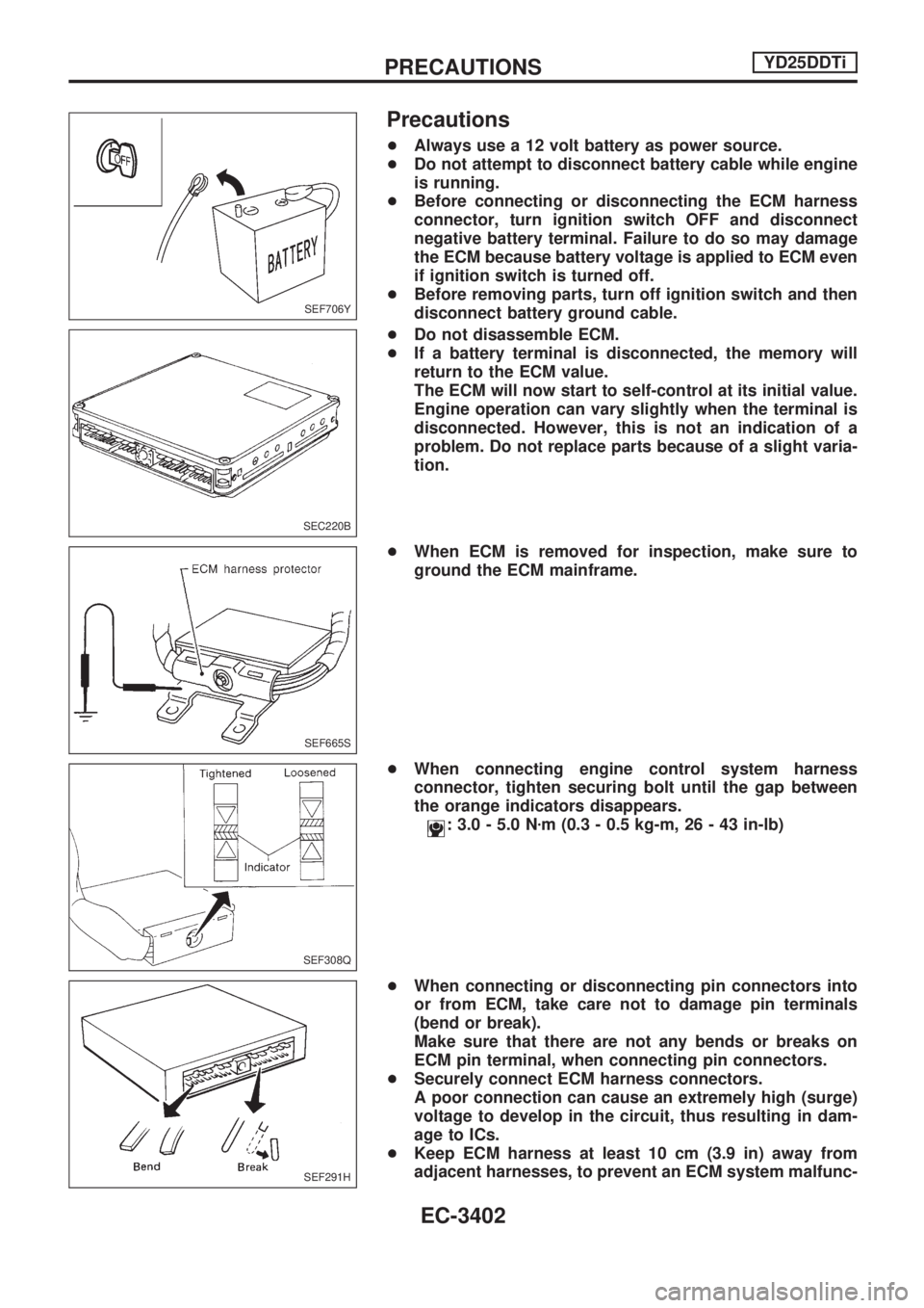
+Always use a 12 volt battery as power source.
+Do not attempt to disconnect battery cable while engine
is running.
+Before connecting or disconnecting the ECM harness
connector, turn ignition switch OFF and disconnect
negative battery terminal. Failure to do so may damage
the ECM because battery voltage is applied to ECM even
if ignition switch is turned off.
+Before removing parts, turn off ignition switch and then
disconnect battery ground cable.
+Do not disassemble ECM.
+If a battery terminal is disconnected, the memory will
return to the ECM value.
The ECM will now start to self-control at its initial value.
Engine operation can vary slightly when the terminal is
disconnected. However, this is not an indication of a
problem. Do not replace parts because of a slight varia-
tion.
+When ECM is removed for inspection, make sure to
ground the ECM mainframe.
+When connecting engine control system harness
connector, tighten securing bolt until the gap between
the orange indicators disappears.
: 3.0 - 5.0 Nzm (0.3 - 0.5 kg-m, 26 - 43 in-lb)
+When connecting or disconnecting pin connectors into
or from ECM, take care not to damage pin terminals
(bend or break).
Make sure that there are not any bends or breaks on
ECM pin terminal, when connecting pin connectors.
+Securely connect ECM harness connectors.
A poor connection can cause an extremely high (surge)
voltage to develop in the circuit, thus resulting in dam-
age to ICs.
+Keep ECM harness at least 10 cm (3.9 in) away from
adjacent harnesses, to prevent an ECM system malfunc-
SEF706Y
SEC220B
SEF665S
SEF308Q
SEF291H
PRECAUTIONSYD25DDTi
EC-3402
Page 450 of 1306
13. Install the front chain case.
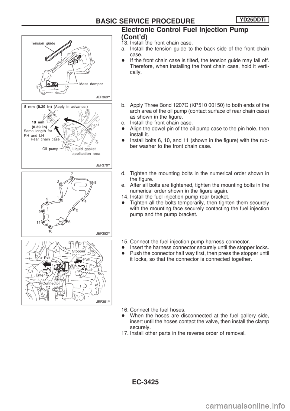
a. Install the tension guide to the back side of the front chain
case.
+If the front chain case is tilted, the tension guide may fall off.
Therefore, when installing the front chain case, hold it verti-
cally.
b. Apply Three Bond 1207C (KP510 00150) to both ends of the
arch area of the oil pump (contact surface of rear chain case)
as shown in the figure.
c. Install the front chain case.
+Align the dowel pin of the oil pump case to the pin hole, then
install it.
+Install bolts 6, 10, and 11 (shown in the figure) with the rub-
ber washer to the front chain case.
d. Tighten the mounting bolts in the numerical order shown in
the figure.
e. After all bolts are tightened, tighten the mounting bolts in the
numerical order shown in the figure again.
14. Install the fuel injection pump rear bracket.
+Tighten all the bolts temporarily, then tighten them securely
with the mounting face securely contacting the fuel injection
pump and the pump bracket.
15. Connect the fuel injection pump harness connector.
+Insert the harness connector securely until the stopper locks.
+Push the connector half way first, then press the stopper until
it locks, so that the connector is connected together.
16. Connect the fuel hoses.
+When the hoses are disconnected at the fuel gallery side,
insert until the hoses contact the valve, then install the clamp
securely.
17. Install other parts in the reverse order of removal.
JEF369Y
JEF370Y
JEF352Y
JEF351Y
BASIC SERVICE PROCEDUREYD25DDTi
Electronic Control Fuel Injection Pump
(Cont'd)
EC-3425
Page 454 of 1306
+Erasing the emission-related diagnostic information using CONSULT-II is easier and quicker than
switching the diagnostic test mode using the data link connector.
NATS (Nissan Anti-Theft System)
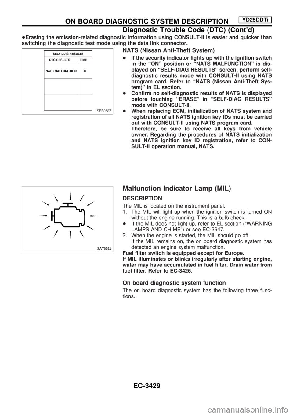
+If the security indicator lights up with the ignition switch
in the ªONº position or ªNATS MALFUNCTIONº is dis-
played on ªSELF-DIAG RESULTSº screen, perform self-
diagnostic results mode with CONSULT-II using NATS
program card. Refer to ªNATS (Nissan Anti-Theft Sys-
tem)º in EL section.
+Confirm no self-diagnostic results of NATS is displayed
before touching ªERASEº in ªSELF-DIAG RESULTSº
mode with CONSULT-II.
+When replacing ECM, initialization of NATS system and
registration of all NATS ignition key IDs must be carried
out with CONSULT-II using NATS program card.
Therefore, be sure to receive all keys from vehicle
owner. Regarding the procedures of NATS initialization
and NATS ignition key ID registration, refer to CON-
SULT-II operation manual, NATS.
Malfunction Indicator Lamp (MIL)
DESCRIPTION
The MIL is located on the instrument panel.
1. The MIL will light up when the ignition switch is turned ON
without the engine running. This is a bulb check.
+If the MIL does not light up, refer to EL section (ªWARNING
LAMPS AND CHIMEº) or see EC-3647.
2. When the engine is started, the MIL should go off.
If the MIL remains on, the on board diagnostic system has
detected an engine system malfunction.
Fuel filter switch is equipped except for Europe.
If MIL illuminates or blinks irregularly after starting engine,
water may have accumulated in fuel filter. Drain water from
fuel filter. Refer to EC-3426.
On board diagnostic system function
The on board diagnostic system has the following three func-
tions.
SEF252Z
SAT652J
ON BOARD DIAGNOSTIC SYSTEM DESCRIPTIONYD25DDTi
Diagnostic Trouble Code (DTC) (Cont'd)
EC-3429
Page 458 of 1306
Relationship between MIL, DTC, CONSULT-II and driving patterns
*1: When a malfunction is detected,
MIL will light up.
*2: When the same malfunction is
detected in two consecutive driving
patterns, MIL will stay lit up.
*3: When a malfunction is detected for
the first time, the DTC will be
stored in ECM.*4: The DTC will not be displayed any
longer after vehicle is driven 40
times without the same malfunc-
tion. (The DTC still remain in
ECM.)*5: Other screens except SELF-DIAG-
NOSTIC RESULTS & DATA MONI-
TOR (AUTO TRIG) cannot display
the malfunction. DATA MONITOR
(AUTO TRIG) can display the mal-
function at the moment it is
detected.
SEC946C
ON BOARD DIAGNOSTIC SYSTEM DESCRIPTIONYD25DDTi
Malfunction Indicator Lamp (MIL) (Cont'd)
EC-3433
Page 488 of 1306
ECM Terminals and Reference Value
PREPARATION
1. ECM is located behind the instrument lower panel. For this
inspection, remove the driver's side instrument lower cover.
2. Remove ECM harness protector.
3. Perform all voltage measurements with the connector con-
nected. Extend tester probe as shown to perform tests eas-
ily.
+Open harness securing clip to make testing easier.
+Use extreme care not to touch 2 pins at one time.
+Data is for comparison and may not be exact.
Be sure ECM unit is properly grounded before checking.
SEC948C
AEC913
SEF367I
SEF665S
TROUBLE DIAGNOSIS Ð GENERAL DESCRIPTIONYD25DDTi
EC-3463
Page 494 of 1306
Description
Intermittent incidents (I/I) may occur. In many cases, the problem resolves itself (the part or circuit function
returns to normal without intervention). It is important to realize that the symptoms described in the custom-
er's complaint often do not recur on DTC visits. Realize also that the most frequent cause of I/I occurrences
is poor electrical connections. Because of this, the conditions under which the incident occurred may not be
clear. Therefore, circuit checks made as part of the standard diagnostic procedure may not indicate the
specific problem area.
COMMON I/I REPORT SITUATIONS
STEP in Work Flow Situation
II The CONSULT-II is used. The SELF-DIAG RESULTS screen shows time data other than ª0º.
III The symptom described by the customer does not recur.
IV DTC does not appear during the DTC Confirmation Procedure.
VI The Diagnostic Procedure for XXXX does not indicate the problem area.
Diagnostic Procedure
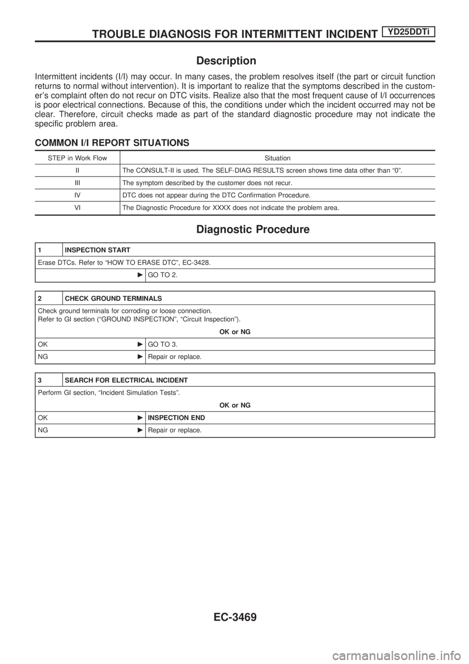
1 INSPECTION START
Erase DTCs. Refer to ªHOW TO ERASE DTCº, EC-3428.
cGO TO 2.
2 CHECK GROUND TERMINALS
Check ground terminals for corroding or loose connection.
Refer to GI section (ªGROUND INSPECTIONº, ªCircuit Inspectionº).
OK or NG
OKcGO TO 3.
NGcRepair or replace.
3 SEARCH FOR ELECTRICAL INCIDENT
Perform GI section, ªIncident Simulation Testsº.
OK or NG
OKcINSPECTION END
NGcRepair or replace.
TROUBLE DIAGNOSIS FOR INTERMITTENT INCIDENTYD25DDTi
EC-3469
Page 818 of 1306
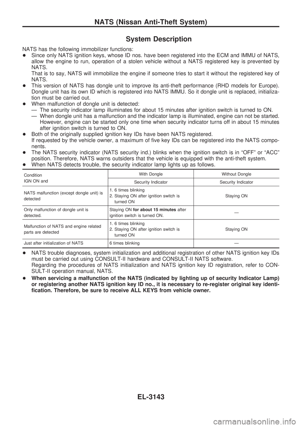
System Description
NATS has the following immobilizer functions:
+Since only NATS ignition keys, whose ID nos. have been registered into the ECM and IMMU of NATS,
allow the engine to run, operation of a stolen vehicle without a NATS registered key is prevented by
NATS.
That is to say, NATS will immobilize the engine if someone tries to start it without the registered key of
NATS.
+This version of NATS has dongle unit to improve its anti-theft performance (RHD models for Europe).
Dongle unit has its own ID which is registered into NATS IMMU. So it dongle unit is replaced, initializa-
tion must be carried out.
+When malfunction of dongle unit is detected:
Ð The security indicator lamp illuminates for about 15 minutes after ignition switch is turned to ON.
Ð When dongle unit has a malfunction and the indicator lamp is illuminated, engine can not be started.
However, engine can be started only one time when security indicator turns off in about 15 minutes
after ignition switch is turned to ON.
+Both of the originally supplied ignition key IDs have been NATS registered.
If requested by the vehicle owner, a maximum of five key IDs can be registered into the NATS compo-
nents.
+The NATS security indicator (NATS security ind.) blinks when the ignition switch is in ªOFFº or ªACCº
position. Therefore, NATS warns outsiders that the vehicle is equipped with the anti-theft system.
+When NATS detects trouble, the security indicator lamp lights up as follows.
Condition
IGN ON andWith Dongle Without Dongle
Security Indicator Security Indicator
NATS malfunction (except dongle unit) is
detected1. 6 times blinking
2. Staying ON after ignition switch is
turned ONStaying ON
Only malfunction of dongle unit is
detected.Staying ONfor about 15 minutesafter
ignition switch is turned ON.Ð
Malfunction of NATS and engine related
parts are detected1. 6 times blinking
2. Staying ON after ignition switch is
turned ONStaying ON
Just after initialization of NATS 6 times blinking Ð
+NATS trouble diagnoses, system initialization and additional registration of other NATS ignition key IDs
must be carried out using CONSULT-II hardware and CONSULT-II NATS software.
Regarding the procedures of NATS initialization and NATS ignition key ID registration, refer to CON-
SULT-II operation manual, NATS.
+When servicing a malfunction of the NATS (indicated by lighting up of security Indicator Lamp)
or registering another NATS ignition key ID no., it is necessary to re-register original key identi-
fication. Therefore, be sure to receive ALL KEYS from vehicle owner.
NATS (Nissan Anti-Theft System)
EL-3143