2001 NISSAN PICK-UP ECU
[x] Cancel search: ECUPage 819 of 1306

System Composition
The immobilizer function of the NATS consists of the following:
+NATS ignition key
+NATS immobilizer control unit (NATS IMMU), located in the ignition key cylinder
+Engine control module (ECM)
+Dongle unit (RHD models for Europe)
+NATS security indicator
SEL148X
NATS (Nissan Anti-Theft System)
EL-3144
Page 823 of 1306
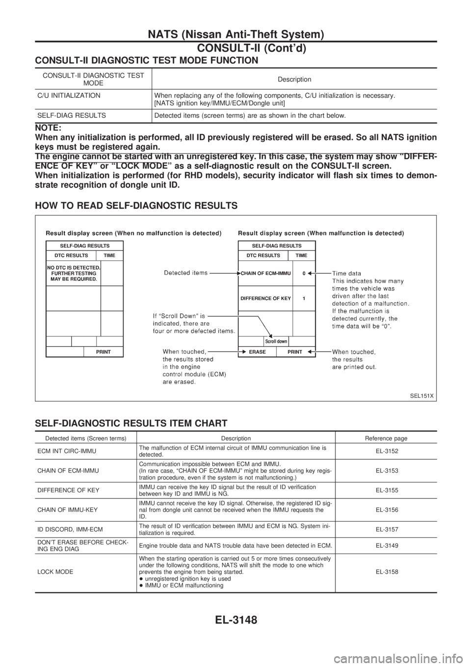
CONSULT-II DIAGNOSTIC TEST MODE FUNCTION
CONSULT-II DIAGNOSTIC TEST
MODEDescription
C/U INITIALIZATION When replacing any of the following components, C/U initialization is necessary.
[NATS ignition key/IMMU/ECM/Dongle unit]
SELF-DIAG RESULTS Detected items (screen terms) are as shown in the chart below.
NOTE:
When any initialization is performed, all ID previously registered will be erased. So all NATS ignition
keys must be registered again.
The engine cannot be started with an unregistered key. In this case, the system may show ªDIFFER-
ENCE OF KEYº or ªLOCK MODEº as a self-diagnostic result on the CONSULT-II screen.
When initialization is performed (for RHD models), security indicator will flash six times to demon-
strate recognition of dongle unit ID.
HOW TO READ SELF-DIAGNOSTIC RESULTS
SELF-DIAGNOSTIC RESULTS ITEM CHART
Detected items (Screen terms) Description Reference page
ECM INT CIRC-IMMUThe malfunction of ECM internal circuit of IMMU communication line is
detected.EL-3152
CHAIN OF ECM-IMMUCommunication impossible between ECM and IMMU.
(In rare case, ªCHAIN OF ECM-IMMUº might be stored during key regis-
tration procedure, even if the system is not malfunctioning.)EL-3153
DIFFERENCE OF KEYIMMU can receive the key ID signal but the result of ID verification
between key ID and IMMU is NG.EL-3155
CHAIN OF IMMU-KEYIMMU cannot receive the key ID signal. Otherwise, the registered ID sig-
nal from dongle unit cannot be received when the IMMU requests the
ID.EL-3156
ID DISCORD, IMM-ECMThe result of ID verification between IMMU and ECM is NG. System ini-
tialization is required.EL-3157
DON'T ERASE BEFORE CHECK-
ING ENG DIAGEngine trouble data and NATS trouble data have been detected in ECM. EL-3149
LOCK MODEWhen the starting operation is carried out 5 or more times consecutively
under the following conditions, NATS will shift the mode to one which
prevents the engine from being started.
+unregistered ignition key is used
+IMMU or ECM malfunctioningEL-3158
SEL151X
NATS (Nissan Anti-Theft System)
CONSULT-II (Cont'd)
EL-3148
Page 824 of 1306
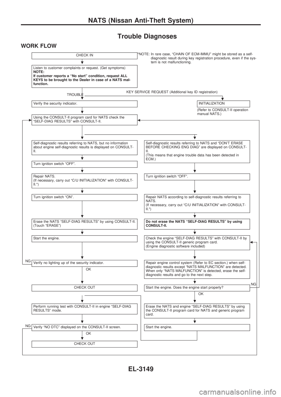
Trouble Diagnoses
WORK FLOW
CHECK IN*NOTE: In rare case, ªCHAIN OF ECM-IMMUº might be stored as a self-
diagnostic result during key registration procedure, even if the sys-
tem is not malfunctioning.
Listen to customer complaints or request. (Get symptoms)
NOTE:
If customer reports a ªNo startº condition, request ALL
KEYS to be brought to the Dealer in case of a NATS mal-
function.
TROUBLEKEY SERVICE REQUEST (Additional key ID registration).Verify the security indicator.INITIALIZATION
(Refer to CONSULT-II operation
manual NATS.)
cUsing the CONSULT-II program card for NATS check the
ªSELF-DIAG RESULTSº with CONSULT-II.b
Self-diagnostic results referring to NATS, but no information
about engine self-diagnostic results is displayed on CONSULT-
II.Self-diagnostic results referring to NATS and ªDON'T ERASE
BEFORE CHECKING ENG DIAGº are displayed on CONSULT-
II.
(This means that engine trouble data has been detected in
ECM.)
Turn ignition switch ªOFFº.
Repair NATS.
(If necessary, carry out ªC/U INITIALIZATIONº with CONSULT-
II.*)Turn ignition switch ªOFFº.
Turn ignition switch ªONº.Repair NATS according to self-diagnostic results referring to
NATS.
(If necessary, carry out ªC/U INITIALIZATIONº with CONSULT-
II.*)
Erase the NATS ªSELF-DIAG RESULTSº by using CONSULT-II.
(Touch ªERASEº)Do not erase the NATS ªSELF-DIAG RESULTSº by using
CONSULT-II.
Start the engine.Check the engine ªSELF-DIAG RESULTSº with CONSULT-II by
using the CONSULT-II generic program card.
(Engine diagnostic software included)b
NGVerify no lighting up of the security indicator.
OKRepair engine control system (Refer to EC section.) when self-
diagnostic results except ªNATS MALFUNCTIONº are detected.
When only ªNATS MALFUNCTIONº is detected, erase the self-
diagnostic results and go to the next step.
CHECK OUTStart the engine. Does the engine start properly?
OKNG
Perform running test with CONSULT-II in engine ªSELF-DIAG
RESULTSº mode.Erase the NATS and engine ªSELF-DIAG RESULTSº by using
the CONSULT-II program card for NATS and generic program
card.
NGVerify ªNO DTCº displayed on the CONSULT-II screen.
OKStart the engine.
CHECK OUT
.
.
.
..
.
..
..
..
..
..
..
..
..
.
NATS (Nissan Anti-Theft System)
EL-3149
Page 825 of 1306
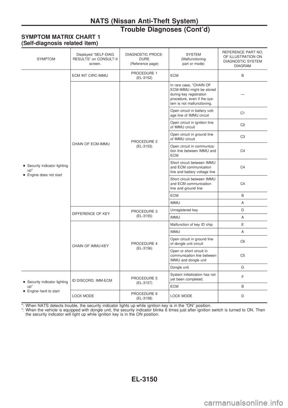
SYMPTOM MATRIX CHART 1
(Self-diagnosis related item)
SYMPTOMDisplayed ªSELF-DIAG
RESULTSº on CONSULT-II
screen.DIAGNOSTIC PROCE-
DURE
(Reference page)SYSTEM
(Malfunctioning
part or mode)REFERENCE PART NO.
OF ILLUSTRATION ON
DIAGNOSTIC SYSTEM
DIAGRAM
+Security indicator lighting
up*
+Engine does not startECM INT CIRC-IMMUPROCEDURE 1
(EL-3152)ECM B
CHAIN OF ECM-IMMUPROCEDURE 2
(EL-3153)In rare case, ªCHAIN OF
ECM-IMMU might be stored
during key registration
procedure, even if the sys-
tem is not malfunctioning.Ð
Open circuit in battery volt-
age line of IMMU circuitC1
Open circuit in ignition line
of IMMU circuitC2
Open circuit in ground line
of IMMU circuitC3
Open circuit in communica-
tion line between IMMU and
ECMC4
Short circuit between IMMU
and ECM communication
line and battery voltage lineC4
Short circuit between IMMU
and ECM communication
line and ground lineC4
ECM B
IMMU A
DIFFERENCE OF KEYPROCEDURE 3
(EL-3155)Unregistered key D
IMMU A
CHAIN OF IMMU-KEYPROCEDURE 4
(EL-3156)Malfunction of key ID chip E
IMMU A
Open circuit in ground line
of dongle unit circuitC6
Open or short circuit in
communication line between
IMMU and dongle unitC5
Dongle unit G
+Security indicator lighting
up*
+Engine hard to startID DISCORD, IMM-ECMPROCEDURE 5
(EL-3157)System initialization has not
yet been completed.F
ECM B
LOCK MODEPROCEDURE 6
(EL-3158)LOCK MODE D
*: When NATS detects trouble, the security indicator lights up while ignition key is in the ªONº position.
*: When the vehicle is equipped with dongle unit, the security indicator blinks 6 times just after ignition switch is turned to ON. Then
the security indicator will light up while ignition key is in the ON position.
NATS (Nissan Anti-Theft System)
Trouble Diagnoses (Cont'd)
EL-3150
Page 826 of 1306
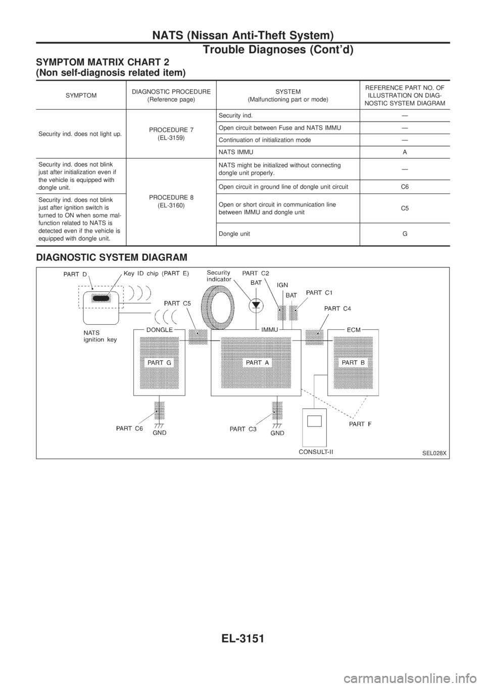
SYMPTOM MATRIX CHART 2
(Non self-diagnosis related item)
SYMPTOMDIAGNOSTIC PROCEDURE
(Reference page)SYSTEM
(Malfunctioning part or mode)REFERENCE PART NO. OF
ILLUSTRATION ON DIAG-
NOSTIC SYSTEM DIAGRAM
Security ind. does not light up.PROCEDURE 7
(EL-3159)Security ind. Ð
Open circuit between Fuse and NATS IMMU Ð
Continuation of initialization mode Ð
NATS IMMU A
Security ind. does not blink
just after initialization even if
the vehicle is equipped with
dongle unit.
PROCEDURE 8
(EL-3160)NATS might be initialized without connecting
dongle unit properly.Ð
Open circuit in ground line of dongle unit circuit C6
Security ind. does not blink
just after ignition switch is
turned to ON when some mal-
function related to NATS is
detected even if the vehicle is
equipped with dongle unit.Open or short circuit in communication line
between IMMU and dongle unitC5
Dongle unit G
DIAGNOSTIC SYSTEM DIAGRAM
SEL028X
NATS (Nissan Anti-Theft System)
Trouble Diagnoses (Cont'd)
EL-3151
Page 834 of 1306
![NISSAN PICK-UP 2001 Repair Manual DIAGNOSTIC PROCEDURE 7
ªSECURITY IND. DOES NOT LIGHT UPº
Check 10A fuse [No.6, located in the
fuse block (J/B)].
OK
cNG
Replace fuse.
NATS INITIALIZATION
1) Install the 10A fuse.
2) Perform initiali NISSAN PICK-UP 2001 Repair Manual DIAGNOSTIC PROCEDURE 7
ªSECURITY IND. DOES NOT LIGHT UPº
Check 10A fuse [No.6, located in the
fuse block (J/B)].
OK
cNG
Replace fuse.
NATS INITIALIZATION
1) Install the 10A fuse.
2) Perform initiali](/manual-img/5/57372/w960_57372-833.png)
DIAGNOSTIC PROCEDURE 7
ªSECURITY IND. DOES NOT LIGHT UPº
Check 10A fuse [No.6, located in the
fuse block (J/B)].
OK
cNG
Replace fuse.
NATS INITIALIZATION
1) Install the 10A fuse.
2) Perform initialization with CON-
SULT-II.
For the operation of
initialization, refer to ªCON-
SULT-II operation manual
NATSº.
Turn ignition switch ªOFFº.
Start engine and turn ignition switch
ªOFFº.
Check the security ind. lighting.
NG
cOK
END
Check voltage between security ind. con-
nectorM55terminalV1(R/G) and
ground.
Voltage: Battery voltage
OK
cNG
Check harness for open or
short between fuse and
security ind.
CHECK INDICATOR LAMP.
OK
cNG
Repair harness.
CHECK NATS IMMU FUNCTION.
1. Connect NATS IMMU connectorM68.
2. Disconnect security ind. connector
M55.
3. Check continuity between NATS IMMU
connector
M68terminalV6(L) and
ground.
Continuity should exist intermit-
tently.
OK
cNG
NATS IMMU is malfunc-
tioning. Replace IMMU.
Perform initializa-
tion with CON-
SULT-II.
For the operation
of initialization,
refer to ªCON-
SULT-II operation
manual NATSº.
Check harness for open or short between
security indicator and NATS IMMU.
SEL931UC
SEL164XA
.
.
.
.
.
.
.
.
.
NATS (Nissan Anti-Theft System)
Trouble Diagnoses (Cont'd)
EL-3159
Page 872 of 1306
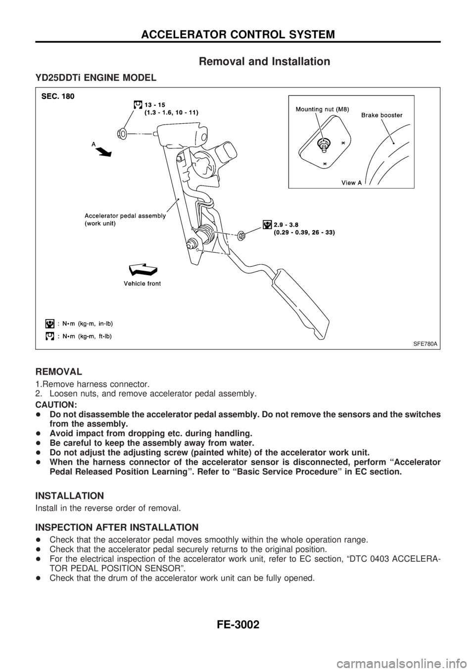
Removal and Installation
YD25DDTi ENGINE MODEL
REMOVAL
1.Remove harness connector.
2. Loosen nuts, and remove accelerator pedal assembly.
CAUTION:
+Do not disassemble the accelerator pedal assembly. Do not remove the sensors and the switches
from the assembly.
+Avoid impact from dropping etc. during handling.
+Be careful to keep the assembly away from water.
+Do not adjust the adjusting screw (painted white) of the accelerator work unit.
+When the harness connector of the accelerator sensor is disconnected, perform ªAccelerator
Pedal Released Position Learningº. Refer to ªBasic Service Procedureº in EC section.
INSTALLATION
Install in the reverse order of removal.
INSPECTION AFTER INSTALLATION
+Check that the accelerator pedal moves smoothly within the whole operation range.
+Check that the accelerator pedal securely returns to the original position.
+For the electrical inspection of the accelerator work unit, refer to EC section, ªDTC 0403 ACCELERA-
TOR PEDAL POSITION SENSORº.
+Check that the drum of the accelerator work unit can be fully opened.
SFE780A
ACCELERATOR CONTROL SYSTEM
FE-3002
Page 904 of 1306
CAUTION:
+After removing timing chain, do not turn crankshaft and
camshaft separately, or valves will strike piston heads.
+When installing camshafts, chain tensioners, oil seals,
or other sliding parts, lubricate contacting surfaces with
new engine oil.
+Apply new engine oil to bolt threads and seat surfaces
when installing camshaft sprockets, crankshaft pulley,
and camshaft brackets.
+Do not spill engine coolant on drive belts.
REMOVAL
1. Remove charge air cooler and bracket.
2. Remove rocker cover. Refer to EM-3045, ªRemoval and
Installationº, ªROCKER COVERº.
3. Remove EGR guide tube.
4. Remove radiator shroud and radiator. Refer to LC section,
ªREMOVAL AND INSTALLATIONº, ªRadiatorº.
5. Remove idler pulley, idler pulley bracket and drive belts.
6. Remove upper and lower oil pans. Refer to EM-3015,
ªRemoval
and Installationº, ªOIL PANº.
7. Remove injection tube.
Refer to EC section, ªInjection Tube and Injection Nozzleº.
8. Remove secondary timing chain and associated parts.
Refer to EM-3021, ªSecondary Timing Chainº.
9. When removing rear chain case, remove camshaft sprock-
ets.
Refer to EM-3047, ªCAMSHAFTº.
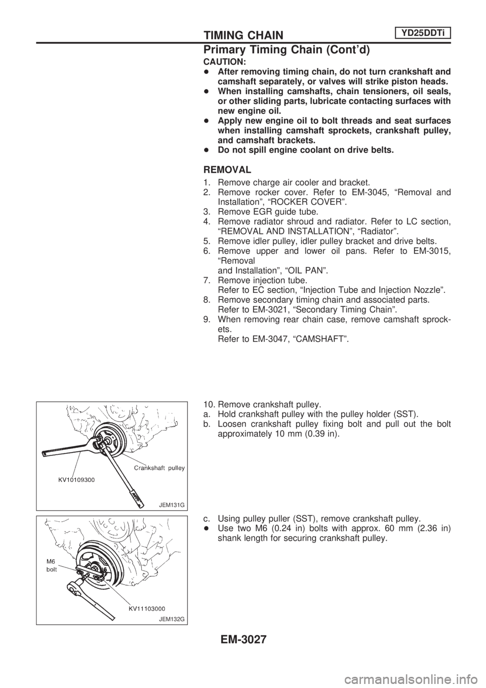
10. Remove crankshaft pulley.
a. Hold crankshaft pulley with the pulley holder (SST).
b. Loosen crankshaft pulley fixing bolt and pull out the bolt
approximately 10 mm (0.39 in).
c. Using pulley puller (SST), remove crankshaft pulley.
+Use two M6 (0.24 in) bolts with approx. 60 mm (2.36 in)
shank length for securing crankshaft pulley.
JEM131G
JEM132G
TIMING CHAINYD25DDTi
Primary Timing Chain (Cont'd)
EM-3027