Page 931 of 1306
3. Heat cylinder head to 110 to 120ÉC (230 to 248ÉF) by soak-
ing in heated oil.
4. Sufficiently cool valve seat with dry ice. Force fit valve seat
into cylinder head.
WARNING:
Do not touch cold valve seat with your bare hands.
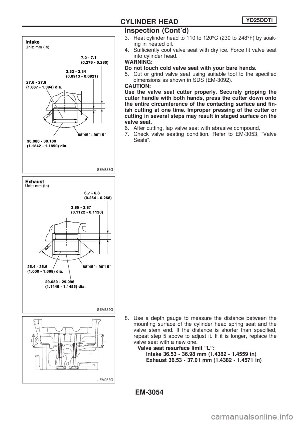
5. Cut or grind valve seat using suitable tool to the specified
dimensions as shown in SDS (EM-3092).
CAUTION:
Use the valve seat cutter properly. Securely gripping the
cutter handle with both hands, press the cutter down onto
the entire circumference of the contacting surface and fin-
ish cutting at one time. Improper pressing of the cutter or
cutting in several steps may result in staged surface on the
valve seat.
6. After cutting, lap valve seat with abrasive compound.
7. Check valve seating condition. Refer to EM-3053, ªValve
Seatsº.
8. Use a depth gauge to measure the distance between the
mounting surface of the cylinder head spring seat and the
valve stem end. If the distance is shorter than specified,
repeat step 5 above to adjust it. If it is longer, replace the
valve seat with a new one.
Valve seat resurface limit ªLº:
Intake 36.53 - 36.98 mm (1.4382 - 1.4559 in)
Exhaust 36.53 - 37.01 mm (1.4382 - 1.4571 in)
SEM888G
SEM889G
JEM253G
CYLINDER HEADYD25DDTi
Inspection (Cont'd)
EM-3054
Page 936 of 1306
CAMSHAFT INSTALLATION
1. Install valve lifters and adjusting shims.
+Install in the correct locations (the same places as before
removal).
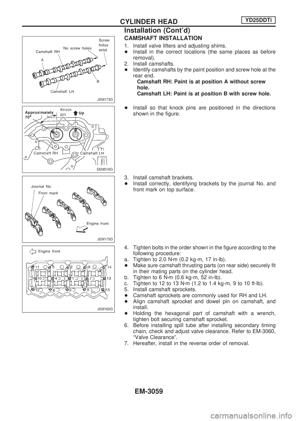
2. Install camshafts.
+Identify camshafts by the paint position and screw hole at the
rear end.
Camshaft RH: Paint is at position A without screw
hole.
Camshaft LH: Paint is at position B with screw hole.
+Install so that knock pins are positioned in the directions
shown in the figure.
3. Install camshaft brackets.
+Install correctly, identifying brackets by the journal No. and
front mark on top surface.
4. Tighten bolts in the order shown in the figure according to the
following procedure:
a. Tighten to 2.0 Nzm (0.2 kg-m, 17 in-lb).
+Make sure camshaft thrusting parts (on rear side) securely fit
in their mating parts on the cylinder head.
b. Tighten to 6 Nzm (0.6 kg-m, 52 in-lb).
c. Tighten to 12 to 13 Nzm (1.2 to 1.4 kg-m, 9 to 10 ft-lb).
5. Install camshaft sprockets.
+Camshaft sprockets are commonly used for RH and LH.
+Align camshaft sprocket and dowel pin on camshaft, and
install.
+Holding the hexagonal part of camshaft with a wrench,
tighten bolt securing camshaft sprocket.
6. Before installing spill tube after installing secondary timing
chain, check and adjust valve clearance. Refer to EM-3060,
ªValve Clearanceº.
7. Hereafter, install in the reverse order of removal.
JEM173G
SEM516G
JEM175G
JEM160G
CYLINDER HEADYD25DDTi
Installation (Cont'd)
EM-3059
Page 941 of 1306
Removal
Preparation
1. Drain coolant from radiator drain plugs.
2. Remove the following parts.
+Engine hood
+Charge air cooler
+Under protector
+Battery
+Radiator shroud
+Radiator
+Accessory belt
+Cooling fan
+Exhaust front tube
Engine room (Left)
3. Remove air duct and air cleaner case.
4. Disconnect harness connectors from alternator and air con-
ditioner compressor.
5. Remove alternator.
6. Remove installation bolts. Relocate air conditioner compres-
sor. Use a rope to temporarily anchor it to vehicle side.
7. Disconnect and relocate heating hose, install blank cap to
hose to prevent coolant from leaking.
8. Remove heat insulator.
Engine room (Right)
9. Remove fuel feed and return hoses.
CAUTION:
Install blank caps immediately to avoid fuel leakage.
10. Remove all harness connectors on the engine, and move
harnesses to the side of the vehicle.
Vehicle underfloor
11. Remove starter motor.
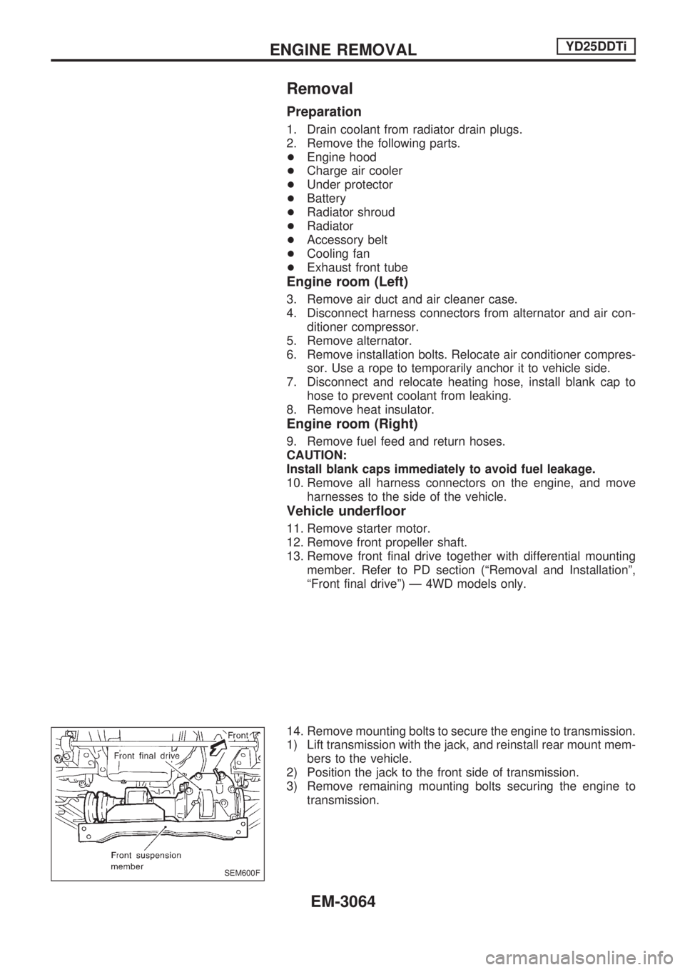
12. Remove front propeller shaft.
13. Remove front final drive together with differential mounting
member. Refer to PD section (ªRemoval and Installationº,
ªFront final driveº) Ð 4WD models only.
14. Remove mounting bolts to secure the engine to transmission.
1) Lift transmission with the jack, and reinstall rear mount mem-
bers to the vehicle.
2) Position the jack to the front side of transmission.
3) Remove remaining mounting bolts securing the engine to
transmission.
SEM600F
ENGINE REMOVALYD25DDTi
EM-3064
Page 942 of 1306
Removal operation
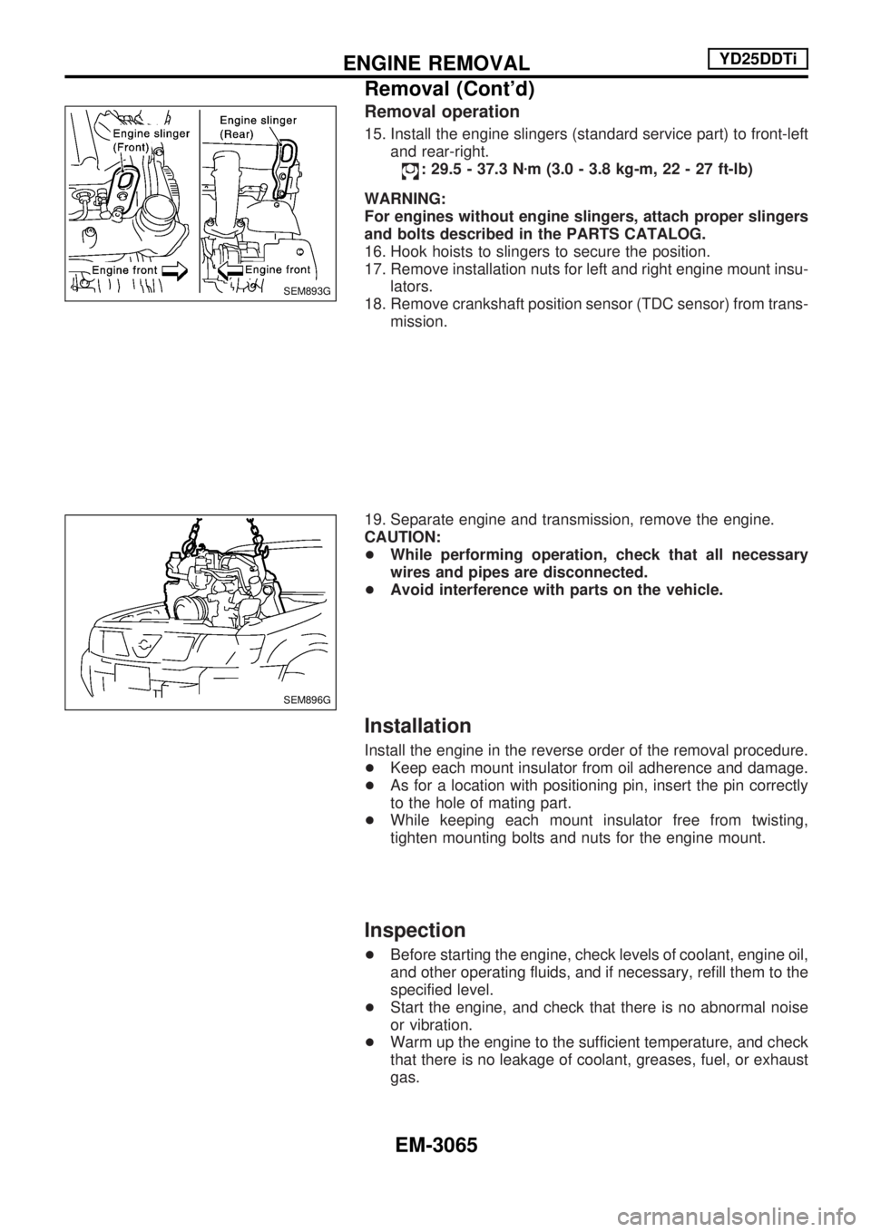
15. Install the engine slingers (standard service part) to front-left
and rear-right.
: 29.5 - 37.3 Nzm (3.0 - 3.8 kg-m, 22 - 27 ft-lb)
WARNING:
For engines without engine slingers, attach proper slingers
and bolts described in the PARTS CATALOG.
16. Hook hoists to slingers to secure the position.
17. Remove installation nuts for left and right engine mount insu-
lators.
18. Remove crankshaft position sensor (TDC sensor) from trans-
mission.
19. Separate engine and transmission, remove the engine.
CAUTION:
+While performing operation, check that all necessary
wires and pipes are disconnected.
+Avoid interference with parts on the vehicle.
Installation
Install the engine in the reverse order of the removal procedure.
+Keep each mount insulator from oil adherence and damage.
+As for a location with positioning pin, insert the pin correctly
to the hole of mating part.
+While keeping each mount insulator free from twisting,
tighten mounting bolts and nuts for the engine mount.
Inspection
+Before starting the engine, check levels of coolant, engine oil,
and other operating fluids, and if necessary, refill them to the
specified level.
+Start the engine, and check that there is no abnormal noise
or vibration.
+Warm up the engine to the sufficient temperature, and check
that there is no leakage of coolant, greases, fuel, or exhaust
gas.
SEM893G
SEM896G
ENGINE REMOVALYD25DDTi
Removal (Cont'd)
EM-3065
Page 944 of 1306
Removal and Installation
CAUTION:
+When installing bearings, pistons, or other sliding parts,
lubricate contacting surfaces with new engine oil.
+Place removed parts such as bearings and bearing caps
in their proper order and direction.
+When installing connecting rod nuts, and main bearing
cap bolts, apply new engine oil to threads and seating
surfaces.
+Do not allow any magnetic materials to contact the sig-
nal plate of flywheel.
+Do not remove the signal plate at back.
+Do not place the signal plate side facing under.
+Handle with care so as not to damage the signal plate
[especially four places on protrusions for signal of crank
position sensor (TDC sensor)].
Disassembly
PISTON AND CRANKSHAFT
1. Remove engine. Refer to ªENGINE REMOVALº, EM-3063.
2. Place engine on a work stand.
a. Remove flywheel.
+Hold ring gear with ring gear stopper (KV10105630,
KV10105610). Then, loosen securing bolts with TORX
socket (size: Q8 E20, Commercial Service Tool) and remove
them. As an alternative method, hold the crankshaft pulley
with a pulley holder (SST) to remove the flywheel.
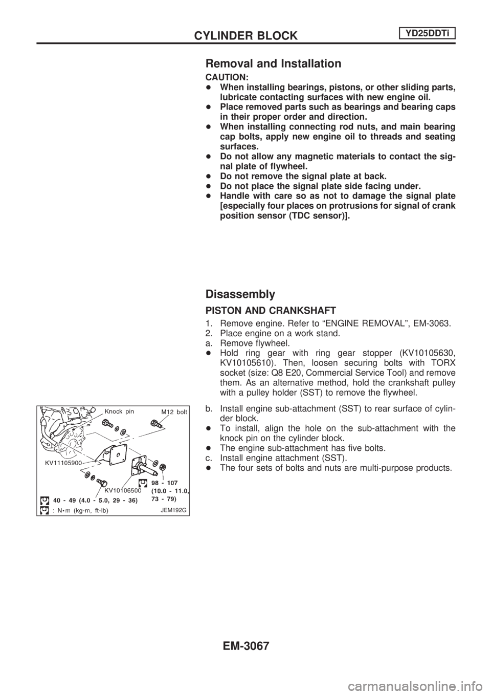
b. Install engine sub-attachment (SST) to rear surface of cylin-
der block.
+To install, align the hole on the sub-attachment with the
knock pin on the cylinder block.
+The engine sub-attachment has five bolts.
c. Install engine attachment (SST).
+The four sets of bolts and nuts are multi-purpose products.
JEM192G
CYLINDER BLOCKYD25DDTi
EM-3067
Page 958 of 1306
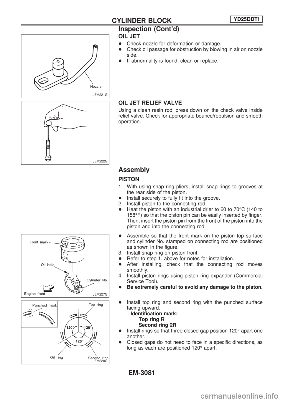
OIL JET
+Check nozzle for deformation or damage.
+Check oil passage for obstruction by blowing in air on nozzle
side.
+If abnormality is found, clean or replace.
OIL JET RELIEF VALVE
Using a clean resin rod, press down on the check valve inside
relief valve. Check for appropriate bounce/repulsion and smooth
operation.
Assembly
PISTON
1. With using snap ring pliers, install snap rings to grooves at
the rear side of the piston.
+Install securely to fully fit into the groove.
2. Install piston to the connecting rod.
+Heat the piston with an industrial drier to 60 to 70ÉC (140 to
158ÉF) so that the piston pin can be easily inserted by finger.
Then, insert the piston pin from the front of the piston into the
piston and into the connecting rod.
+Assemble so that the front mark on the piston top surface
and cylinder No. stamped on connecting rod are positioned
as shown in the figure.
3. Install snap ring on piston front.
+Refer to step 1. above for notes for installation.
+After installing, check that the connecting rod moves
smoothly.
4. Install piston rings using piston ring expander (Commercial
Service Tool).
+Be extremely careful to avoid any damage to the piston.
+Install top ring and second ring with the punched surface
facing upward.
Identification mark:
Top ring R
Second ring 2R
+Install rings so that three closed gap position 120É apart one
another.
+Closed gaps do not need to face in a specific directions, as
long as each are positioned 120É apart.
JEM221G
JEM222G
JEM227G
JEM228G
CYLINDER BLOCKYD25DDTi
Inspection (Cont'd)
EM-3081
Page 961 of 1306
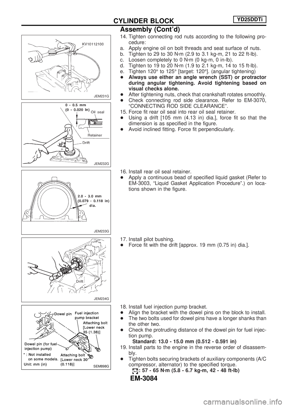
14. Tighten connecting rod nuts according to the following pro-
cedure:
a. Apply engine oil on bolt threads and seat surface of nuts.
b. Tighten to 29 to 30 Nzm (2.9 to 3.1 kg-m, 21 to 22 ft-lb).
c. Loosen completely to 0 Nzm (0 kg-m, 0 in-lb).
d. Tighten to 19 to 20 Nzm (1.9 to 2.1 kg-m, 14 to 15 ft-lb).
e. Tighten 120É to 125É [target: 120É]. (angular tightening)
+Always use either an angle wrench (SST) or protractor
during angular tightening. Avoid tightening based on
visual checks alone.
+After tightening nuts, check that crankshaft rotates smoothly.
+Check connecting rod side clearance. Refer to EM-3070,
ªCONNECTING ROD SIDE CLEARANCEº.
15. Force fit rear oil seal into rear oil seal retainer.
+Using a drift [105 mm (4.13 in) dia.], force fit so that the
dimension is as specified in the figure.
+Avoid inclined fitting. Force fit perpendicularly.
16. Install rear oil seal retainer.
+Apply a continuous bead of specified liquid gasket (Refer to
EM-3003, ªLiquid Gasket Application Procedureº.) on loca-
tions shown in the figure.
17. Install pilot bushing.
+Force fit with the drift [approx. 19 mm (0.75 in) dia.].
18. Install fuel injection pump bracket.
+Align the bracket with the dowel pins on the block to install.
+The two bolts used for dowel pins have a longer shanks than
the other two.
+Check the protruding distance of the dowel pin for fuel injec-
tion pump.
Standard: 13.0 - 15.0 mm (0.512 - 0.591 in)
19. Install parts to the engine in the reverse order of disassem-
bly.
+Tighten bolts securing brackets of auxiliary components (A/C
compressor, alternator) to the specified torque.
:57-65Nzm (5.8 - 6.7 kg-m, 42 - 48 ft-lb)
JEM231G
JEM232G
JEM233G
JEM234G
SEM898G
CYLINDER BLOCKYD25DDTi
Assembly (Cont'd)
EM-3084
Page 962 of 1306
20. Remove engine from engine stand in the reverse order of
assembly.
21. Install flywheel.
+Holding ring gear with ring stopper (SST), tighten securing
bolts with TORX-socket (size: Q8 E20, Commercial Service
Tool).
+Tighten bolts uniformly in a crisscross manner.
REPLACEMENT OF PILOT BUSHING
1. Remove pilot bushing using tool or suitable tool.
2. Install pilot bushing as shown.
SEM500G
SEM275GA
CYLINDER BLOCKYD25DDTi
Assembly (Cont'd)
EM-3085