2001 NISSAN PICK-UP ECU
[x] Cancel search: ECUPage 1005 of 1306
Checking Refrigerant Leaks
CHECKING PROCEDURE
To prevent inaccurate or false readings, make sure there is
no refrigerant vapor or tobacco smoke in the vicinity of the
vehicle. Perform the leak test in calm area (low air/wind
movement) so that the leaking refrigerant is not dispersed.
1. Turn engine off.
2. Connect a suitable A/C manifold gauge set to the A/C ser-
vice ports.
3. Check if the A/C refrigerant pressure is at least 345 kPa
(3.452 bar, 3.52 kg/cm
2, 50 psi) above 16ÉC (61ÉF). If less
than specification, evacuate and recharge the system with
the specified amount of refrigerant.
NOTE: At temperatures below 16ÉC (61ÉF), leaks may not be
detected since the system may not reach 345 kPa
(3.452 bar, 3.52 kg/cm
2, 50 psi).
4. Conduct the leak test from the high side to the low side at
points
jathroughjn. Refer to HA-3030.
Perform a leak check for the following areas carefully. Clean
the component to be checked and move the leak detector
probe completely around the connection/component.
+Compressor
Check the fitting of high and low pressure hoses, relief valve
and shaft seal.
+Liquid tank
Check the pressure switch, tube fitting, weld seams and the
fusible plug mounts.
+Service valves
Check all around the service valves. Ensure service valve
caps are secured on the service valves (to prevent leaks).
NOTE: After removing A/C manifold gauge set from service
valves, wipe any residue from valves to prevent any
false readings by leak detector.
+Cooling unit (Evaporator)
Turn blower fan on ªHighº for at least 15 seconds to dissipate
any refrigerant trace in the cooling unit. Insert the leak detec-
tor probe into the drain hose immediately after stopping the
engine. (Keep the probe inserted for at least ten seconds.)
5. If a leak detector detects a leak, verify at least once by
blowing compressed air into area of suspected leak, then
repeat check.
6. Do not stop when one leak is found. Continue to check for
additional leaks at all system components.
7. Start engine.
8. Set the heater A/C control as follows:
a. A/C switch ON
b. Face mode
c. Recirculation switch ON
d. Max cold temperature
e. Fan speed high
9. Run engine at 1,500 rpm for at least 2 minutes.
10. Turn engine off and perform leak check again following steps
4 through 6 above.
SERVICE PROCEDURESMANUAL AND AUTO
HA-3031
Page 1009 of 1306
Function and System Application
Diagnostic test
modeFunction ENGINE A/T ABS AIR BAG
Work supportThis mode enables a technician to
adjust some devices faster and more
accurate by following the indications
on CONSULT-II.xxÐÐ
Self-diagnostic
resultsSelf-diagnostic results can be read
and erased quickly.xxxx
Trouble diagnos-
tic recordCurrent self-diagnostic results and all
trouble diagnostic records previously
stored can be read.ÐÐÐ x
ECU discrimi-
nated No.Classification number of a replace-
ment ECU can be read to prevent an
incorrect ECU from being installed.ÐÐÐ x
Data monitorInput/Output data in the ECU (ECM)
can be read.xxxÐ
DTC work sup-
portThis mode enables a technician to
set operating conditions to confirm
self-diagnosis status/results.ÐxÐÐ
Active testDiagnostic Test Mode in which CON-
SULT-II drives some actuators apart
from the ECMs and also shifts some
parameters in a specified range.xÐxÐ
ECU (ECM) part
numberECU (ECM) part number can be
read.xxxÐ
x: Applicable
Nickel Metal Hydride Battery Replacement
CONSULT-II contains a nickel metal hydride battery. When replacing the battery obey the following:
WARNING:
Replace the nickel metal hydride battery with Genuine CONSULT-II battery only. Use of another bat-
tery may present a risk of fire or explosion. The battery may present a fire or chemical burn hazard
if mistreated. Do not recharge, disassemble of dispose of in fire.
Keep the battery out of reach of children and discard used battery conforming to the local regula-
tions.
CONSULT-II CHECKING SYSTEM
GI-3002
Page 1021 of 1306

+Tighten bolt securing transmission.
YD25DDTi engine model
Bolt No. Tightening torque Nzm (kg-m, ft-lb)!mm (in)
V139 - 49 (4.0 - 5.0, 29 - 36) 90 (3.54)
V239 - 49 (4.0 - 5.0, 29 - 36) 95 (3.74)
V339 - 49 (4.0 - 5.0, 29 - 36) 75 (2.95)
SMT144E
REMOVAL AND INSTALLATIONFS5R30A
Installation (Cont'd)
MT-3003
Page 1054 of 1306
neck to prevent the radiator filler neck from deforming.
+If any abnormalities are found, repair or replace the malfunc-
tioning parts.
Water Pump
REMOVAL AND INSTALLATION
CAUTION:
+When removing water pump assembly, be careful not to
get coolant on drive belt.
+Water pump cannot be disassembled and should be
replaced as a unit.
+After installing water pump, connect hose and clamp
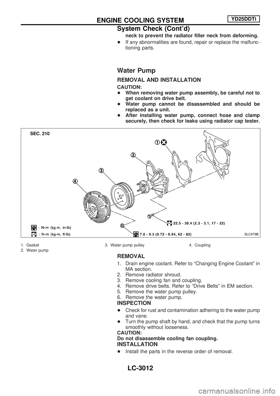
securely, then check for leaks using radiator cap tester.
1. Gasket
2. Water pump3. Water pump pulley 4. Coupling
REMOVAL
1. Drain engine coolant. Refer to ªChanging Engine Coolantº in
MA section.
2. Remove radiator shroud.
3. Remove cooling fan and coupling.
4. Remove drive belts. Refer to ªDrive Beltsº in EM section.
5. Remove the water pump pulley.
6. Remove the water pump.
INSPECTION
+Check for rust and contamination adhering to the water pump
and vane.
+Turn the pump shaft by hand, and check that the pump turns
smoothly without looseness.
CAUTION:
Do not disassemble cooling fan coupling.
INSTALLATION
+Install the parts in the reverse order of removal.
SLC479B
ENGINE COOLING SYSTEMYD25DDTi
System Check (Cont'd)
LC-3012
Page 1082 of 1306
Disposal of Air Bag Module and Seat Belt
Pre-tensioner
+Before disposing of air bag module and seat belt pre-tensioner, or vehicles equipped with such systems,
deploy the systems. If such systems have already been deployed due to an accident, dispose of them as
indicated in ªDISPOSING OF AIR BAG MODULE AND SEAT BELT PRE-TENSIONERº (RS-3013).
+When deploying the air bag module and seat belt pre-tensioner, always use the Special Service Tool;
Deployment tool KV99106400.
+When deploying the air bag module and seat belt pre-tensioner, stand at least 5 m (16 ft) away from the
deployment component.
+When deploying air bag module and seat belt pre-tensioner, a fairly loud noise is made, followed by
smoke being released. The smoke is not poisonous, however, be careful not to inhale smoke since it
irritates the throat and can cause choking.
+Always activate one air bag module at a time.
+Due to heat, leave air bag module unattended for more than 30 minutes after deployment. Also leave
seat belt pre-tensioner unattended for move than 10 minutes after deployment.
+Be sure to wear gloves when handling a deployed air bag module and seat belt pre-tensioner.
+Never apply water to the deployed air bag module and seat belt pre-tensioner.
+Wash your hands clean after finishing work.
+Place the vehicle outdoors with an open space of at least 6 m (20 ft) on all sides when deploying air
bag module and seat belt pre-tensioner while mounted in vehicle.
+Use a voltmeter to make sure the vehicle battery is fully charged.
+Do not dispose of the air bag module and seat belt pre-tensioner un-deployed.
DEPLOYMENT PROCEDURES FOR AIR BAG
MODULE (OUTSIDE OF VEHICLE)
Unless the vehicle is being scrapped, deploying the air bag in the
vehicle is not recommended. This may cause damage to the
vehicle interior.
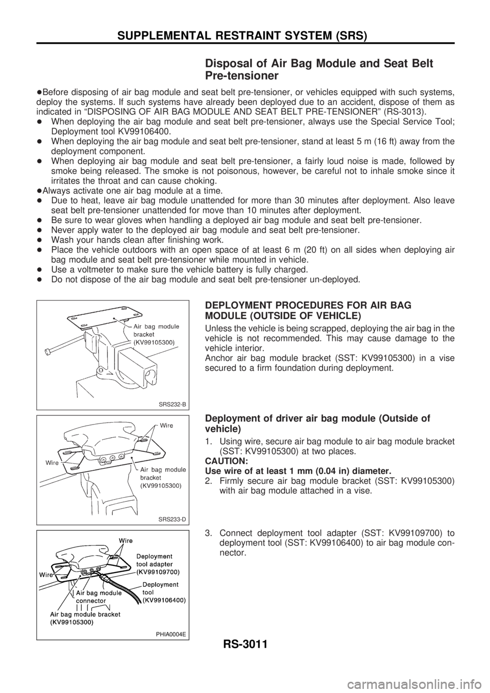
Anchor air bag module bracket (SST: KV99105300) in a vise
secured to a firm foundation during deployment.
Deployment of driver air bag module (Outside of
vehicle)
1. Using wire, secure air bag module to air bag module bracket
(SST: KV99105300) at two places.
CAUTION:
Use wire of at least 1 mm (0.04 in) diameter.
2. Firmly secure air bag module bracket (SST: KV99105300)
with air bag module attached in a vise.
3. Connect deployment tool adapter (SST: KV99109700) to
deployment tool (SST: KV99106400) to air bag module con-
nector.
SRS232-B
SRS233-D
PHIA0004E
SUPPLEMENTAL RESTRAINT SYSTEM (SRS)
RS-3011
Page 1085 of 1306
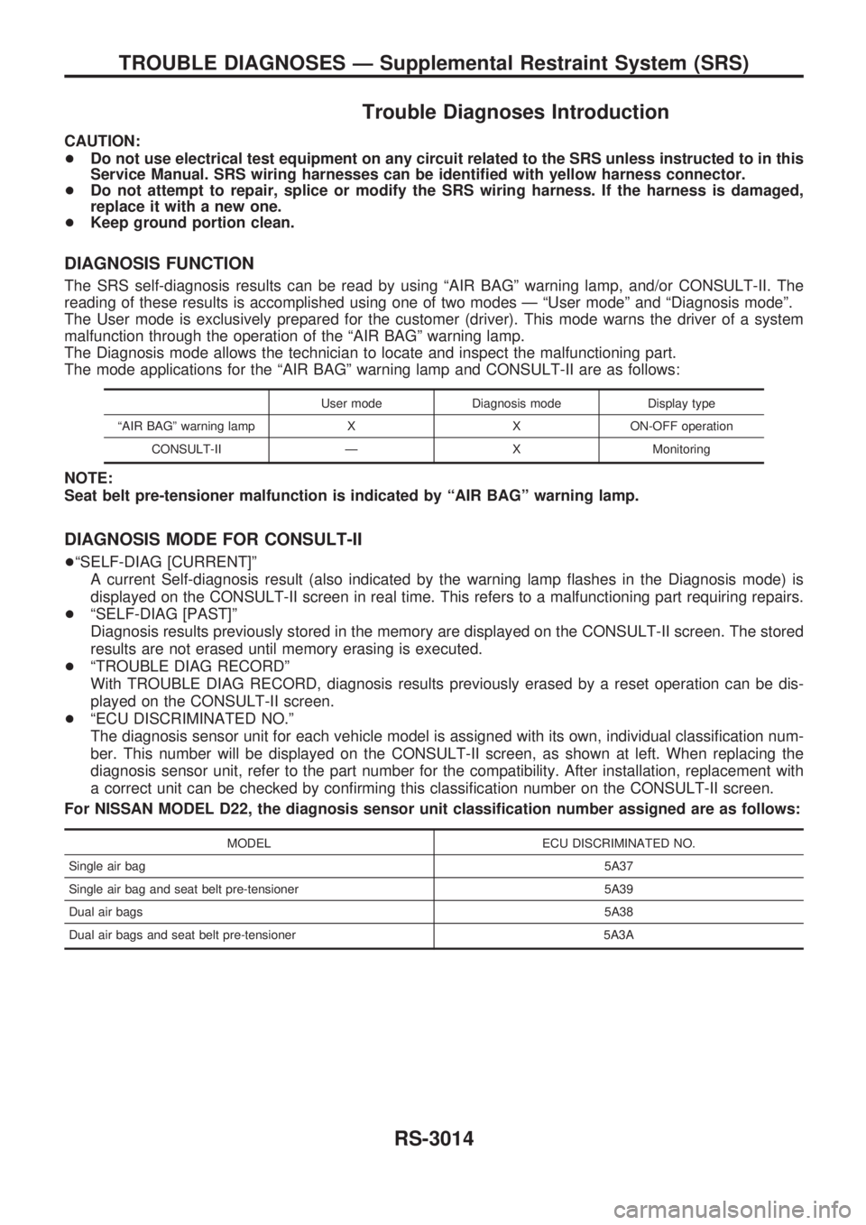
Trouble Diagnoses Introduction
CAUTION:
+Do not use electrical test equipment on any circuit related to the SRS unless instructed to in this
Service Manual. SRS wiring harnesses can be identified with yellow harness connector.
+Do not attempt to repair, splice or modify the SRS wiring harness. If the harness is damaged,
replace it with a new one.
+Keep ground portion clean.
DIAGNOSIS FUNCTION
The SRS self-diagnosis results can be read by using ªAIR BAGº warning lamp, and/or CONSULT-II. The
reading of these results is accomplished using one of two modes Ð ªUser modeº and ªDiagnosis modeº.
The User mode is exclusively prepared for the customer (driver). This mode warns the driver of a system
malfunction through the operation of the ªAIR BAGº warning lamp.
The Diagnosis mode allows the technician to locate and inspect the malfunctioning part.
The mode applications for the ªAIR BAGº warning lamp and CONSULT-II are as follows:
User mode Diagnosis mode Display type
ªAIR BAGº warning lamp X X ON-OFF operation
CONSULT-II Ð X Monitoring
NOTE:
Seat belt pre-tensioner malfunction is indicated by ªAIR BAGº warning lamp.
DIAGNOSIS MODE FOR CONSULT-II
+ªSELF-DIAG [CURRENT]º
A current Self-diagnosis result (also indicated by the warning lamp flashes in the Diagnosis mode) is
displayed on the CONSULT-II screen in real time. This refers to a malfunctioning part requiring repairs.
+ªSELF-DIAG [PAST]º
Diagnosis results previously stored in the memory are displayed on the CONSULT-II screen. The stored
results are not erased until memory erasing is executed.
+ªTROUBLE DIAG RECORDº
With TROUBLE DIAG RECORD, diagnosis results previously erased by a reset operation can be dis-
played on the CONSULT-II screen.
+ªECU DISCRIMINATED NO.º
The diagnosis sensor unit for each vehicle model is assigned with its own, individual classification num-
ber. This number will be displayed on the CONSULT-II screen, as shown at left. When replacing the
diagnosis sensor unit, refer to the part number for the compatibility. After installation, replacement with
a correct unit can be checked by confirming this classification number on the CONSULT-II screen.
For NISSAN MODEL D22, the diagnosis sensor unit classification number assigned are as follows:
MODEL ECU DISCRIMINATED NO.
Single air bag5A37
Single air bag and seat belt pre-tensioner 5A39
Dual air bags5A38
Dual air bags and seat belt pre-tensioner 5A3A
TROUBLE DIAGNOSES Ð Supplemental Restraint System (SRS)
RS-3014
Page 1254 of 1306
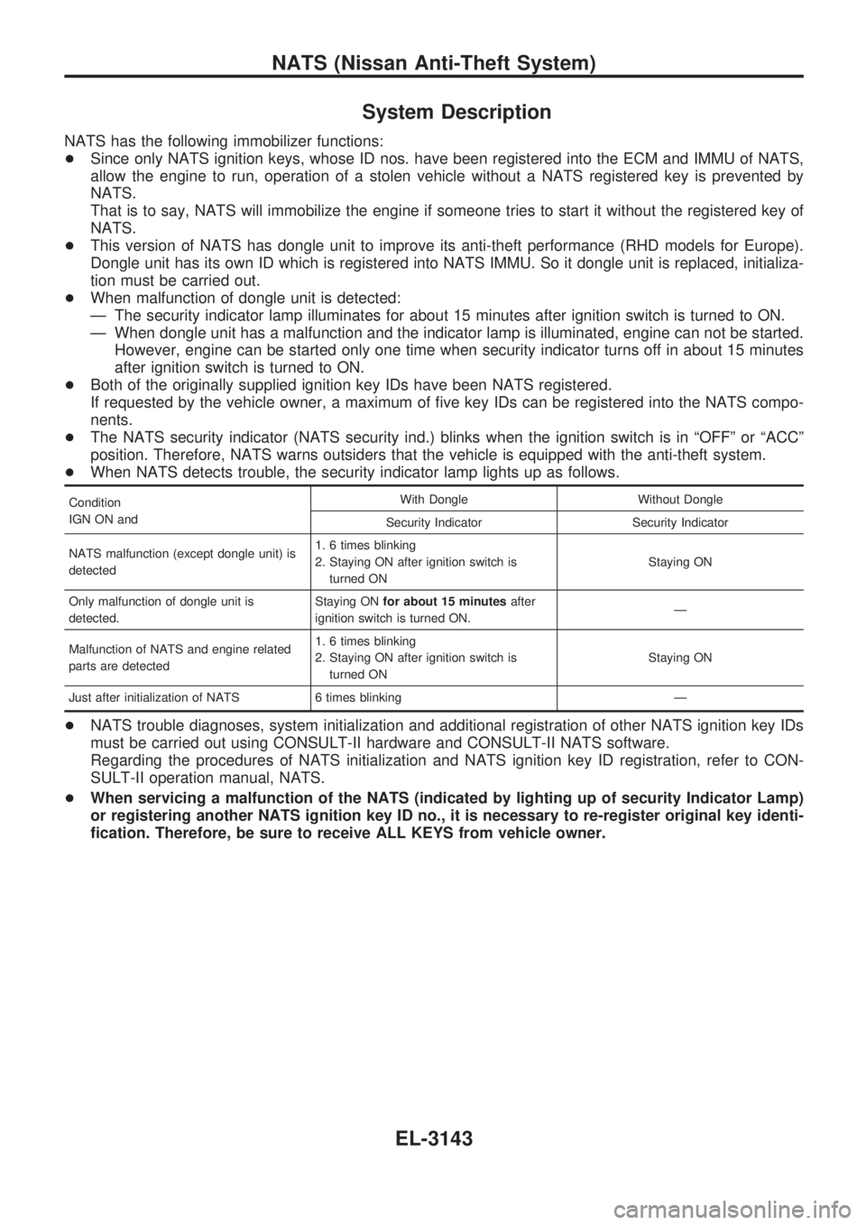
System Description
NATS has the following immobilizer functions:
+Since only NATS ignition keys, whose ID nos. have been registered into the ECM and IMMU of NATS,
allow the engine to run, operation of a stolen vehicle without a NATS registered key is prevented by
NATS.
That is to say, NATS will immobilize the engine if someone tries to start it without the registered key of
NATS.
+This version of NATS has dongle unit to improve its anti-theft performance (RHD models for Europe).
Dongle unit has its own ID which is registered into NATS IMMU. So it dongle unit is replaced, initializa-
tion must be carried out.
+When malfunction of dongle unit is detected:
Ð The security indicator lamp illuminates for about 15 minutes after ignition switch is turned to ON.
Ð When dongle unit has a malfunction and the indicator lamp is illuminated, engine can not be started.
However, engine can be started only one time when security indicator turns off in about 15 minutes
after ignition switch is turned to ON.
+Both of the originally supplied ignition key IDs have been NATS registered.
If requested by the vehicle owner, a maximum of five key IDs can be registered into the NATS compo-
nents.
+The NATS security indicator (NATS security ind.) blinks when the ignition switch is in ªOFFº or ªACCº
position. Therefore, NATS warns outsiders that the vehicle is equipped with the anti-theft system.
+When NATS detects trouble, the security indicator lamp lights up as follows.
Condition
IGN ON andWith Dongle Without Dongle
Security Indicator Security Indicator
NATS malfunction (except dongle unit) is
detected1. 6 times blinking
2. Staying ON after ignition switch is
turned ONStaying ON
Only malfunction of dongle unit is
detected.Staying ONfor about 15 minutesafter
ignition switch is turned ON.Ð
Malfunction of NATS and engine related
parts are detected1. 6 times blinking
2. Staying ON after ignition switch is
turned ONStaying ON
Just after initialization of NATS 6 times blinking Ð
+NATS trouble diagnoses, system initialization and additional registration of other NATS ignition key IDs
must be carried out using CONSULT-II hardware and CONSULT-II NATS software.
Regarding the procedures of NATS initialization and NATS ignition key ID registration, refer to CON-
SULT-II operation manual, NATS.
+When servicing a malfunction of the NATS (indicated by lighting up of security Indicator Lamp)
or registering another NATS ignition key ID no., it is necessary to re-register original key identi-
fication. Therefore, be sure to receive ALL KEYS from vehicle owner.
NATS (Nissan Anti-Theft System)
EL-3143
Page 1255 of 1306

System Composition
The immobilizer function of the NATS consists of the following:
+NATS ignition key
+NATS immobilizer control unit (NATS IMMU), located in the ignition key cylinder
+Engine control module (ECM)
+Dongle unit (RHD models for Europe)
+NATS security indicator
SEL148X
NATS (Nissan Anti-Theft System)
EL-3144