Page 164 of 1306

DTC No.Trouble diag-
nosis nameDTC detecting condition Possible cause
P0038
0038Heated oxy-
gen sensor 2
heater con-
trol circuit
high+The current amperage in the heated oxygen sen-
sor 2 heater circuit is out of the normal range.
(An excessively high voltage signal is sent to
ECM through the heated oxygen sensor 2
heater.)+Harness or connectors
(The heated oxygen sensor 2 heater circuit
is shorted.)
+Heated oxygen sensor 2 heater
DTC Confirmation ProcedureNEEC0184NOTE:
If ªDTC Confirmation Procedureº has been previously conducted,
always turn ignition switch OFF and wait at least 5 seconds before
conducting the next test.
TESTING CONDITION:
Before performing the following procedure, confirm that bat-
tery voltage is in between 10.5V at idle.
SEF175Y
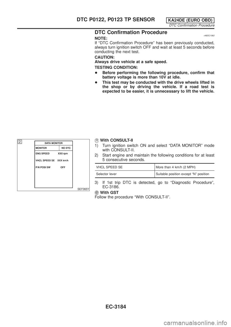
With CONSULT-II
1) Turn ignition switch ON and select ªDATA MONITORº mode
with CONSULT-II.
2) Start engine and drive vehicle at a speed of more than 70 km/h
(43 MPH) for 2 consecutive minutes.
3) If 1st trip DTC is detected, go to ªDiagnostic Procedureº,
EC-3141.
With GST
1) Start engine.
2) Drive vehicle at a speed of more than 70 km/h (43 MPH) for 2
consecutive minutes.
3) Stop vehicle and let engine idle for at least 6 seconds.
4) Turn ignition switch OFF and wait at least 10 seconds.
5) Start engine.
6) Drive vehicle at a speed of more than 70 km/h (43 MPH) for 2
consecutive minutes
7) Stop vehicle and let engine idle for at least 6 seconds.
8) Select ªMODE 3º with GST.
9) If DTC is detected, go to ªDiagnostic Procedureº, EC-3141.
When using GST, ªDTC Confirmation Procedureº should be
performed twice as much as when using CONSULT-II because
GST cannot display MODE 7 (1st trip DTC) concerning this
diagnosis. Therefore, using CONSULT-II is recommended.
DTC P0037, P0038 HO2S2 HEATERKA24DE (EURO OBD)
On Board Diagnosis Logic
EC-3139
Page 170 of 1306

SEF243Y
SEF175Y
PROCEDURE FOR MALFUNCTION BNEEC0054S04With CONSULT-II
1) Turn ignition switch ON.
2) Start engine and warm it up to normal operating temperature.
If engine cannot be started, go to ªDiagnostic Procedureº,
EC-3147.
3) Select ªDATA MONITORº mode with CONSULT-II.
4) Check the voltage of ªMAS A/F SE-B1º with ªDATA MONITORº.
5) Increases engine speed to about 4,000 rpm.
6) Monitor the linear voltage rise in response to engine speed
increases.
If NG, go to ªDiagnostic Procedureº, EC-3147.
If OK, go to following step.
7) Maintain the following conditions for at least 10 consecutive
seconds.
ENG SPEED More than 2,000 rpm
THRTL POS SEN More than 3V
Selector lever Suitable position
Driving location Driving vehicle uphill (Increased engine load)
will help maintain the driving conditions
required for this test.
8) If 1st trip DTC is detected, go to ªDiagnostic Procedureº,
EC-3147.
SEF534P
Overall Function CheckNEEC0055Use this procedure to check the overall function of the mass air flow
sensor circuit. During this check, a 1st trip DTC might not be con-
firmed.
PROCEDURE FOR MALFUNCTION BNEEC0055S01With GST
1) Turn ignition switch ON.
2) Start engine and warm it up to normal operating temperature.
3) Select ªMODE 1º with GST.
4) Check the mass air flow sensor signal with ªMODE 1º.
5) Check for linear mass air flow rise in response to increases to
about 4,000 rpm in engine speed.
6) If NG, go to ªDiagnostic Procedureº, EC-3147.
DTC P0101 MAF SENSORKA24DE (EURO OBD)
DTC Confirmation Procedure
EC-3145
Page 198 of 1306
SEF245Y
SEF178Y
8) Select ªAUTO TRIGº in ªDATA MONITORº mode with CON-
SULT-II.
9) Maintain the following conditions for at least 10 consecutive
seconds.
ENG SPEED More than 2,000 rpm
MAS A/F SE-B1 More than 3V
COOLAN TEMP/S More than 70ÉC (158ÉF)
Selector lever Suitable position
Driving location Driving vehicle uphill (Increased engine load)
will help maintain the driving conditions
required for this test.
10) If 1st trip DTC is detected, go to ªDiagnostic Procedureº,
EC-3175.
With GST
Follow the procedure ªWith CONSULT-IIº.
DTC P0121 TP SENSORKA24DE (EURO OBD)
DTC Confirmation Procedure
EC-3173
Page 209 of 1306

DTC Confirmation Procedure=NEEC1562NOTE:
If ªDTC Confirmation Procedureº has been previously conducted,
always turn ignition switch OFF and wait at least 5 seconds before
conducting the next test.
CAUTION:
Always drive vehicle at a safe speed.
TESTING CONDITION:
+Before performing the following procedure, confirm that
battery voltage is more than 10V at idle.
+This test may be conducted with the drive wheels lifted in
the shop or by driving the vehicle. If a road test is
expected to be easier, it is unnecessary to lift the vehicle.
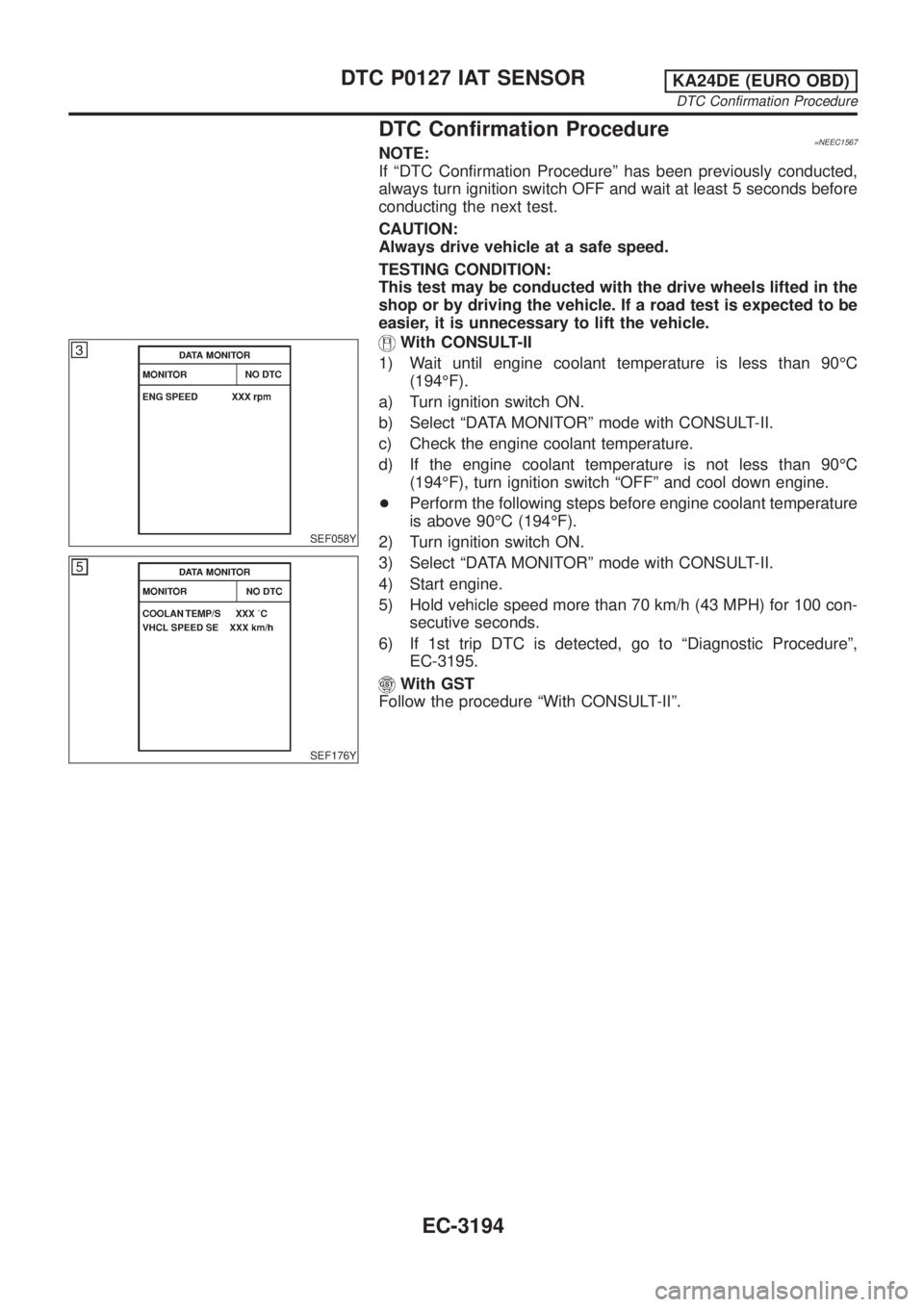
SEF065Y
With CONSULT-II
1) Turn ignition switch ON and select ªDATA MONITORº mode
with CONSULT-II.
2) Start engine and maintain the following conditions for at least
5 consecutive seconds.
VHCL SPEED SE More than 4 km/h (2 MPH)
Selector lever Suitable position except ªNº position
3) If 1st trip DTC is detected, go to ªDiagnostic Procedureº,
EC-3186.
With GST
Follow the procedure ªWith CONSULT-IIº.
DTC P0122, P0123 TP SENSORKA24DE (EURO OBD)
DTC Confirmation Procedure
EC-3184
Page 219 of 1306

DTC Confirmation Procedure=NEEC1567NOTE:
If ªDTC Confirmation Procedureº has been previously conducted,
always turn ignition switch OFF and wait at least 5 seconds before
conducting the next test.
CAUTION:
Always drive vehicle at a safe speed.
TESTING CONDITION:
This test may be conducted with the drive wheels lifted in the
shop or by driving the vehicle. If a road test is expected to be
easier, it is unnecessary to lift the vehicle.
SEF058Y
SEF176Y
With CONSULT-II
1) Wait until engine coolant temperature is less than 90ÉC
(194ÉF).
a) Turn ignition switch ON.
b) Select ªDATA MONITORº mode with CONSULT-II.
c) Check the engine coolant temperature.
d) If the engine coolant temperature is not less than 90ÉC
(194ÉF), turn ignition switch ªOFFº and cool down engine.
+Perform the following steps before engine coolant temperature
is above 90ÉC (194ÉF).
2) Turn ignition switch ON.
3) Select ªDATA MONITORº mode with CONSULT-II.
4) Start engine.
5) Hold vehicle speed more than 70 km/h (43 MPH) for 100 con-
secutive seconds.
6) If 1st trip DTC is detected, go to ªDiagnostic Procedureº,
EC-3195.
With GST
Follow the procedure ªWith CONSULT-IIº.
DTC P0127 IAT SENSORKA24DE (EURO OBD)
DTC Confirmation Procedure
EC-3194
Page 246 of 1306

SEF189Y
DTC Confirmation ProcedureNEEC0175NOTE:
If ªDTC Confirmation Procedureº has been previously conducted,
always turn ignition switch OFF and wait at least 5 seconds before
conducting the next test.
With CONSULT-II
1) Turn ignition switch ON and select ªDATA MONITORº mode
with CONSULT-II.
2) Start engine and drive vehicle at a speed of more than 70 km/h
(43 MPH) for 2 consecutive minutes.
3) Maintain the following conditions for at least 5 consecutive
seconds.
ENG SPEED 1,100 - 3,600 rpm
VHCL SPEED SE 32 - 120 km/h (20 - 75 MPH)
B/FUEL SCHDL 3.5 - 15.5 msec
COOLAN TEMP/S More than 70ÉC (158ÉF)
Selector lever Suitable position
4) If 1st trip DTC is detected, go to ªDiagnostic Procedureº,
EC-3223.
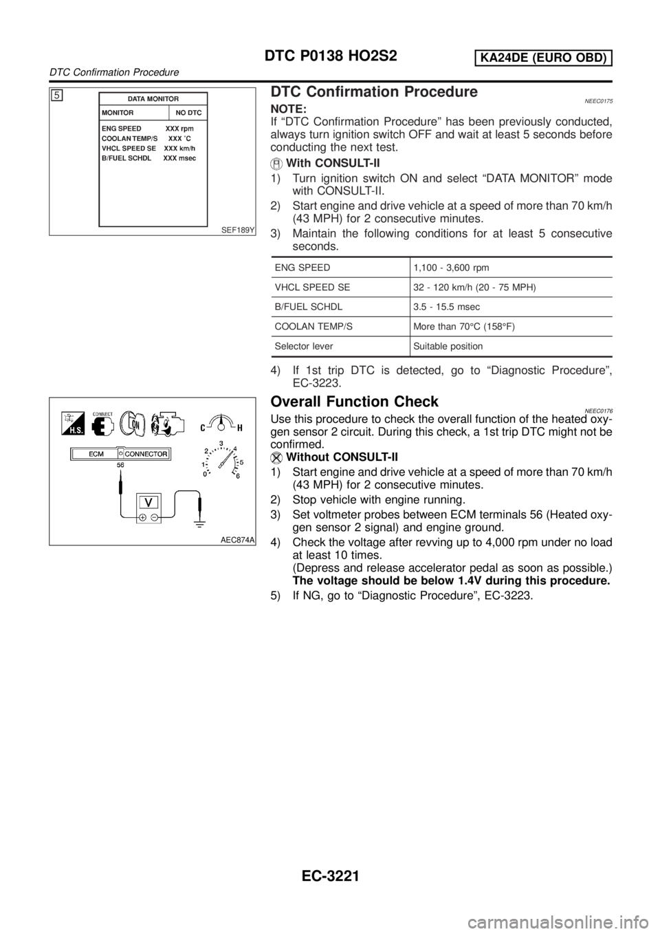
AEC874A
Overall Function CheckNEEC0176Use this procedure to check the overall function of the heated oxy-
gen sensor 2 circuit. During this check, a 1st trip DTC might not be
confirmed.
Without CONSULT-II
1) Start engine and drive vehicle at a speed of more than 70 km/h
(43 MPH) for 2 consecutive minutes.
2) Stop vehicle with engine running.
3) Set voltmeter probes between ECM terminals 56 (Heated oxy-
gen sensor 2 signal) and engine ground.
4) Check the voltage after revving up to 4,000 rpm under no load
at least 10 times.
(Depress and release accelerator pedal as soon as possible.)
The voltage should be below 1.4V during this procedure.
5) If NG, go to ªDiagnostic Procedureº, EC-3223.
DTC P0138 HO2S2KA24DE (EURO OBD)
DTC Confirmation Procedure
EC-3221
Page 249 of 1306

6 CHECK HARNESS CONNECTOR
Check heated oxygen sensor 2 harness connector for water.
Water should not exist.
OK or NG
OK (With CONSULT-II)©GO TO 7.
OK (Without CONSULT-
II)©GO TO 8.
NG©Repair or replace harness connector.
7 CHECK HEATED OXYGEN SENSOR 2
With CONSULT-II
1. Reconnect all harness connectors disconnected.
2. Start engine and drive vehicle at a speed of more than 70 km/h (43 MPH) for 2 consecutive minutes.
3. Stop vehicle with engine running.
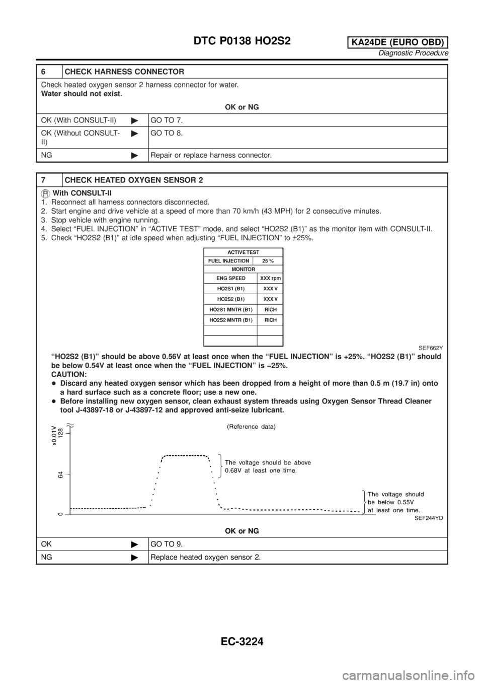
4. Select ªFUEL INJECTIONº in ªACTIVE TESTº mode, and select ªHO2S2 (B1)º as the monitor item with CONSULT-II.
5. Check ªHO2S2 (B1)º at idle speed when adjusting ªFUEL INJECTIONº to±25%.
SEF662Y
ªHO2S2 (B1)º should be above 0.56V at least once when the ªFUEL INJECTIONº is +25%. ªHO2S2 (B1)º should
be below 0.54V at least once when the ªFUEL INJECTIONº is þ25%.
CAUTION:
+Discard any heated oxygen sensor which has been dropped from a height of more than 0.5 m (19.7 in) onto
a hard surface such as a concrete floor; use a new one.
+Before installing new oxygen sensor, clean exhaust system threads using Oxygen Sensor Thread Cleaner
tool J-43897-18 or J-43897-12 and approved anti-seize lubricant.
SEF244YD
OK or NG
OK©GO TO 9.
NG©Replace heated oxygen sensor 2.
DTC P0138 HO2S2KA24DE (EURO OBD)
Diagnostic Procedure
EC-3224
Page 250 of 1306

8 CHECK HEATED OXYGEN SENSOR 2
Without CONSULT-II
1. Reconnect all harness connectors disconnected.
2. Start engine and drive vehicle at a speed of more than 70 km/h (43 MPH) for 2 consecutive minutes.
3. Stop vehicle with engine running.
4. Set voltmeter probes between ECM terminals 56 (Heated oxygen sensor 2 signal) and engine ground.
AEC874A
5. Check the voltage when revving up to 4,000 rpm under no load at least 10 times.
(Depress and release accelerator pedal as soon as possible.)
The voltage should be above 0.56V at least once.
If the voltage is above 0.56V at step 4, step 5 is not necessary.
6. Check the voltage when revving up to 5,000 rpm under no load. Or keep vehicle at idling for 10 minutes, then check
the voltage. Or check the voltage when coasting from 80 km/h (50 MPH) in 3rd gear position (M/T), ªDº position with
ªODº OFF (A/T).
The voltage should be below 0.54V at least once.
CAUTION:
+Discard any heated oxygen sensor which has been dropped from a height of more than 0.5 m (19.7 in) onto
a hard surface such as a concrete floor; use a new one.
+Before installing new oxygen sensor, clean exhaust system threads using Oxygen Sensor Thread Cleaner
tool J-43897-18 or J-43897-12 and approved anti-seize lubricant.
OK or NG
OK©GO TO 9.
NG©Replace heated oxygen sensor 2.
9 CHECK SHIELD CIRCUIT
1. Turn ignition switch OFF.
2. Disconnect joint connector-3.
3. Check harness continuity between joint connector-3 terminal 1 and ground. Refer to wiring diagram.
Continuity should exist.
4. Also check harness for short to power.
5. Then reconnect joint connector-3.
OK or NG
OK©GO TO 11.
NG©GO TO 10.
10 DETECT MALFUNCTIONING PART
Check the following.
+Joint connector-3 (Refer to ªHARNESS LAYOUTº, EL section.)
+Harness for open or short between joint connector-3 and engine ground
©Repair open circuit, short to power in harness or connectors.
DTC P0138 HO2S2KA24DE (EURO OBD)
Diagnostic Procedure
EC-3225