Page 179 of 1306
Wiring DiagramNEEC1554
GEC237A
DTC P0102, P0103 MAF SENSORKA24DE (EURO OBD)
Wiring Diagram
EC-3154
Page 182 of 1306
6 CHECK GROUND CIRCUIT
1. Turn ignition switch OFF.
2. Disconnect ECM harness connector.
3. Check harness continuity between mass air flow sensor terminal 2 and ECM terminal 55. Refer to EC-3154.
SEF124V
Continuity should exist.
4. Also check harness for short to ground or short to power.
OK or NG
OK©GO TO 7.
NG©Repair open circuit or short to ground or short to power in harness or connectors.
7 CHECK INPUT SIGNAL CIRCUIT
1. Check harness continuity between terminal 1 and ECM terminal 54. Refer to wiring diagram.
Continuity should exist.
2. Also check harness for short to ground and short to power.
OK or NG
OK©GO TO 8.
NG©Repair open circuit or short to ground or short to power in harness or connectors.
DTC P0102, P0103 MAF SENSORKA24DE (EURO OBD)
Diagnostic Procedure
EC-3157
Page 187 of 1306
Wiring DiagramNEEC0069
GEC238A
DTC P0112, P0113 IAT SENSORKA24DE (EURO OBD)
Wiring Diagram
EC-3162
Page 192 of 1306
Wiring DiagramNEEC0076
GEC239A
DTC P0117, P0118 ECT SENSORKA24DE (EURO OBD)
Wiring Diagram
EC-3167
Page 193 of 1306

Diagnostic ProcedureNEEC0077
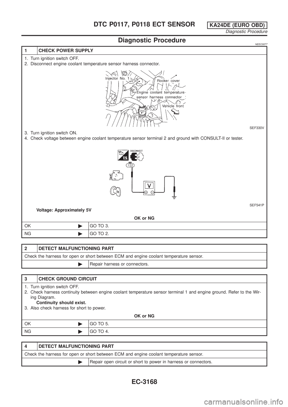
1 CHECK POWER SUPPLY
1. Turn ignition switch OFF.
2. Disconnect engine coolant temperature sensor harness connector.
SEF330V
3. Turn ignition switch ON.
4. Check voltage between engine coolant temperature sensor terminal 2 and ground with CONSULT-II or tester.
SEF541P
Voltage: Approximately 5V
OK or NG
OK©GO TO 3.
NG©GO TO 2.
2 DETECT MALFUNCTIONING PART
Check the harness for open or short between ECM and engine coolant temperature sensor.
©Repair harness or connectors.
3 CHECK GROUND CIRCUIT
1. Turn ignition switch OFF.
2. Check harness continuity between engine coolant temperature sensor terminal 1 and engine ground. Refer to the Wir-
ing Diagram.
Continuity should exist.
3. Also check harness for short to power.
OK or NG
OK©GO TO 5.
NG©GO TO 4.
4 DETECT MALFUNCTIONING PART
Check the harness for open or short between ECM and engine coolant temperature sensor.
©Repair open circuit or short to power in harness or connectors.
DTC P0117, P0118 ECT SENSORKA24DE (EURO OBD)
Diagnostic Procedure
EC-3168
Page 199 of 1306
Wiring DiagramNEEC0084
GEC243A
DTC P0121 TP SENSORKA24DE (EURO OBD)
Wiring Diagram
EC-3174
Page 201 of 1306
5 CHECK POWER SUPPLY
1. Disconnect throttle position sensor harness connector.
SEF265S
2. Turn ignition switch ON.
3. Check voltage between terminal 1 and ground with CONSULT-II or tester.
SEF564P
Voltage: Approximately 5V
OK or NG
OK©GO TO 6.
NG©Repair harness or connectors.
6 CHECK GROUND CIRCUIT
1. Turn ignition switch OFF.
2. Check harness continuity between throttle position sensor terminal 3 and engine ground. Refer to the Wiring Diagram.
SEF565P
Continuity should exist.
3. Also check harness for short to power.
OK or NG
OK©GO TO 8.
NG©GO TO 7.
DTC P0121 TP SENSORKA24DE (EURO OBD)
Diagnostic Procedure
EC-3176
Page 202 of 1306

7 DETECT MALFUNCTIONING PART
Check harness for open or short between ECM and throttle position sensor.
©Repair open circuit or short to power in harness or connectors.
8 CHECK INPUT SIGNAL CIRCUIT
1. Disconnect ECM harness connector.
2. Check harness continuity between ECM terminal 23 and terminal 2.
Refer to the Wiring Diagram.
Continuity should exist.
3. Also check harness for short to ground and short to power.
OK or NG
OK (With CONSULT-II)©GO TO 9.
OK (Without CONSULT-
II)©GO TO 10.
NG©Repair open circuit or short to ground or short to power in harness or connectors.
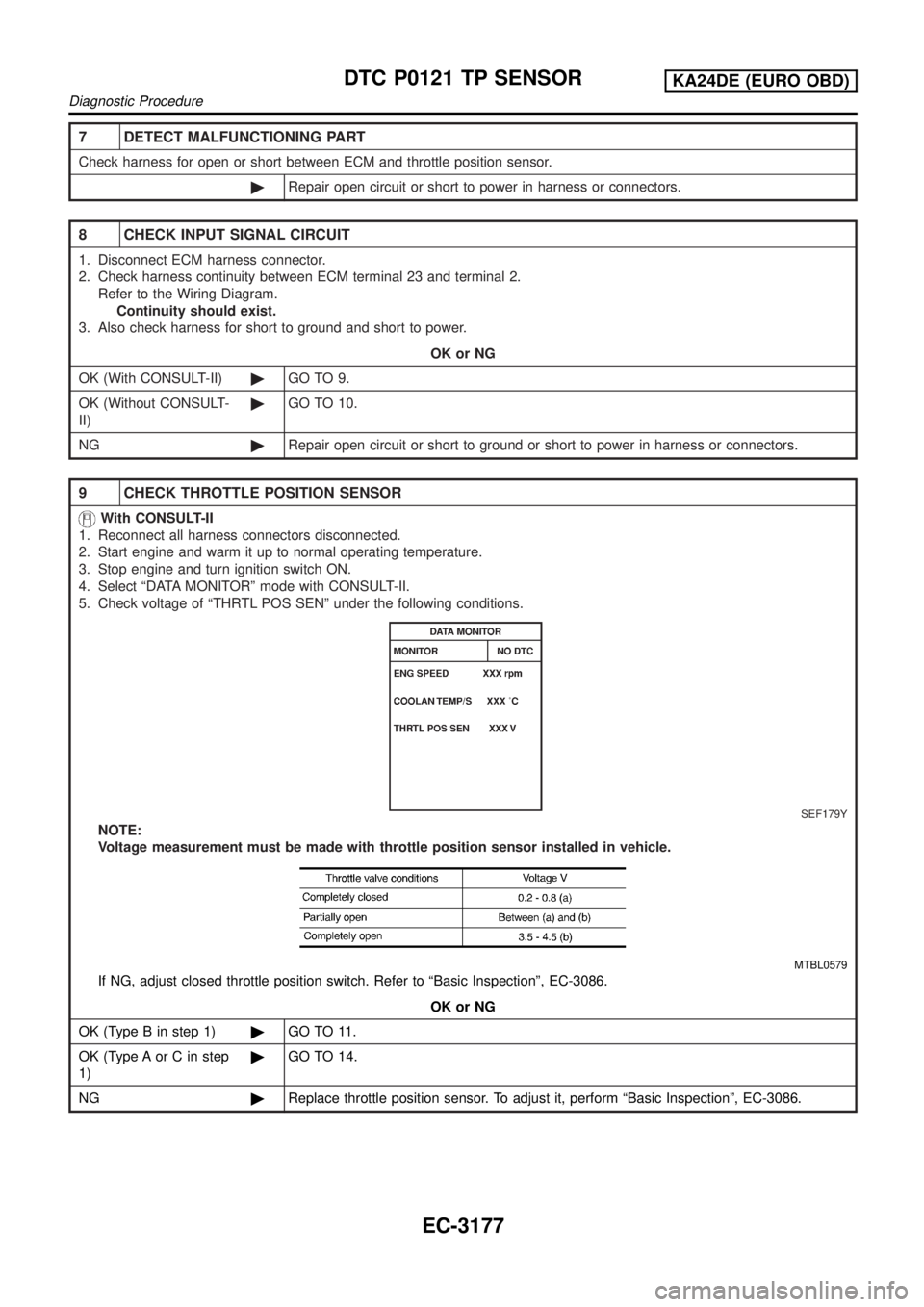
9 CHECK THROTTLE POSITION SENSOR
With CONSULT-II
1. Reconnect all harness connectors disconnected.
2. Start engine and warm it up to normal operating temperature.
3. Stop engine and turn ignition switch ON.
4. Select ªDATA MONITORº mode with CONSULT-II.
5. Check voltage of ªTHRTL POS SENº under the following conditions.
SEF179Y
NOTE:
Voltage measurement must be made with throttle position sensor installed in vehicle.
MTBL0579
If NG, adjust closed throttle position switch. Refer to ªBasic Inspectionº, EC-3086.
OK or NG
OK (Type B in step 1)©GO TO 11.
OK (Type A or C in step
1)©GO TO 14.
NG©Replace throttle position sensor. To adjust it, perform ªBasic Inspectionº, EC-3086.
DTC P0121 TP SENSORKA24DE (EURO OBD)
Diagnostic Procedure
EC-3177