Page 293 of 1306

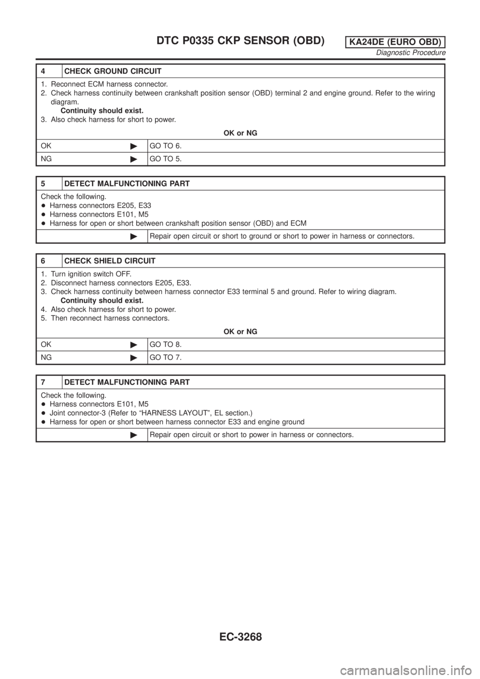
4 CHECK GROUND CIRCUIT
1. Reconnect ECM harness connector.
2. Check harness continuity between crankshaft position sensor (OBD) terminal 2 and engine ground. Refer to the wiring
diagram.
Continuity should exist.
3. Also check harness for short to power.
OK or NG
OK©GO TO 6.
NG©GO TO 5.
5 DETECT MALFUNCTIONING PART
Check the following.
+Harness connectors E205, E33
+Harness connectors E101, M5
+Harness for open or short between crankshaft position sensor (OBD) and ECM
©Repair open circuit or short to ground or short to power in harness or connectors.
6 CHECK SHIELD CIRCUIT
1. Turn ignition switch OFF.
2. Disconnect harness connectors E205, E33.
3. Check harness continuity between harness connector E33 terminal 5 and ground. Refer to wiring diagram.
Continuity should exist.
4. Also check harness for short to power.
5. Then reconnect harness connectors.
OK or NG
OK©GO TO 8.
NG©GO TO 7.
7 DETECT MALFUNCTIONING PART
Check the following.
+Harness connectors E101, M5
+Joint connector-3 (Refer to ªHARNESS LAYOUTº, EL section.)
+Harness for open or short between harness connector E33 and engine ground
©Repair open circuit or short to power in harness or connectors.
DTC P0335 CKP SENSOR (OBD)KA24DE (EURO OBD)
Diagnostic Procedure
EC-3268
Page 298 of 1306
Wiring DiagramNEEC0224
GEC235A
DTC P0340 CMP SENSORKA24DE (EURO OBD)
Wiring Diagram
EC-3273
Page 300 of 1306

3 CHECK POWER SUPPLY
1. Disconnect camshaft position sensor harness connector.
SEC276D
2. Turn ignition switch ON.
3. Check voltage between terminal 5 and ground with CONSULT-II or tester.
SEF040S
Voltage: Battery voltage
OK or NG
OK©GO TO 5.
NG©GO TO 4.
4 DETECT MALFUNCTIONING PART
Check the following.
+Harness connectors E101, M5
+Harness for open or short between camshaft position sensor and ECM relay
+Harness for open or short between camshaft position sensor and ECM
©Repair open circuit or short to ground or short to power in harness or connectors.
5 CHECK INPUT SIGNAL CIRCUIT
1. Turn ignition switch OFF.
2. Disconnect ECM harness connector.
3. Check harness continuity between sensor terminal 4 and ECM terminal 49 or (44)*, sensor terminal 3 and ECM termi-
nals 44, 48 or (49, 53)*. Refer to wiring diagram.
Continuity should exist.
*: Model with NATS (Nissan Anti-Theft System)
4. Also check harness for short to ground and short to power.
OK or NG
OK©GO TO 6.
NG©Repair open circuit or short to ground or short to power in harness or connectors.
DTC P0340 CMP SENSORKA24DE (EURO OBD)
Diagnostic Procedure
EC-3275
Page 301 of 1306
6 CHECK GROUND CIRCUIT
1. Turn ignition switch OFF.
2. Check harness continuity between distributor (camshaft position sensor) terminal 6 and engine ground. Refer to the
wiring diagram.
Continuity should exist.
3. Also check harness for short to power.
OK or NG
OK©GO TO 8.
NG©GO TO 7.
7 DETECT MALFUNCTIONING PART
Check the following.
+Joint connector-3
+Harness for open or short between camshaft position sensor and engine ground
©Repair open circuit or short to ground or short to power in harness or connectors.
8 CHECK CAMSHAFT POSITION SENSOR
1. Reconnect all harness connector disconnected.
2. Start engine and warm it up to normal operating temperature.
3. Check voltage between ECM terminal 49 or (44)* and engine ground, ECM terminals 44, 48 or (49, 53)* and engine
ground.
SEC273D
*: Model with NATS (Nissan Anti-Theft System)
OK or NG
OK©GO TO 9.
NG©Replace camshaft position sensor.
DTC P0340 CMP SENSORKA24DE (EURO OBD)
Diagnostic Procedure
EC-3276
Page 306 of 1306
5 CHECK INJECTORS
1. Refer to Wiring Diagram for Injectors, EC-3370.
2. Stop engine and then turn ignition switch ON.
3. Check voltage between ECM terminals 102, 104, 109 and 111 and ground with CONSULT-II or tester.
LEC041A
Battery voltage should exist.
OK or NG
OK©GO TO 6.
NG©Perform ªDiagnostic Procedureº INJECTOR, EC-3371.
6 CHECK IGNITION SPARK
1. Disconnect ignition wire from spark plug.
2. Connect a known good spark plug to the ignition wire.
3. Place end of spark plug against a suitable ground and crank engine.
4. Check for spark.
SEF282G
OK or NG
OK©GO TO 8.
NG©GO TO 7.
DTC P0420 THREE WAY CATALYST
FUNCTION
KA24DE (EURO OBD)
Diagnostic Procedure
EC-3281
Page 311 of 1306
Wiring DiagramNEEC0253
GEC249A
DTC P0444, P0445 EVAP CANISTER PURGE VOLUME CONTROL SOLENOID
VALVE
KA24DE (EURO OBD)
Wiring Diagram
EC-3286
Page 312 of 1306

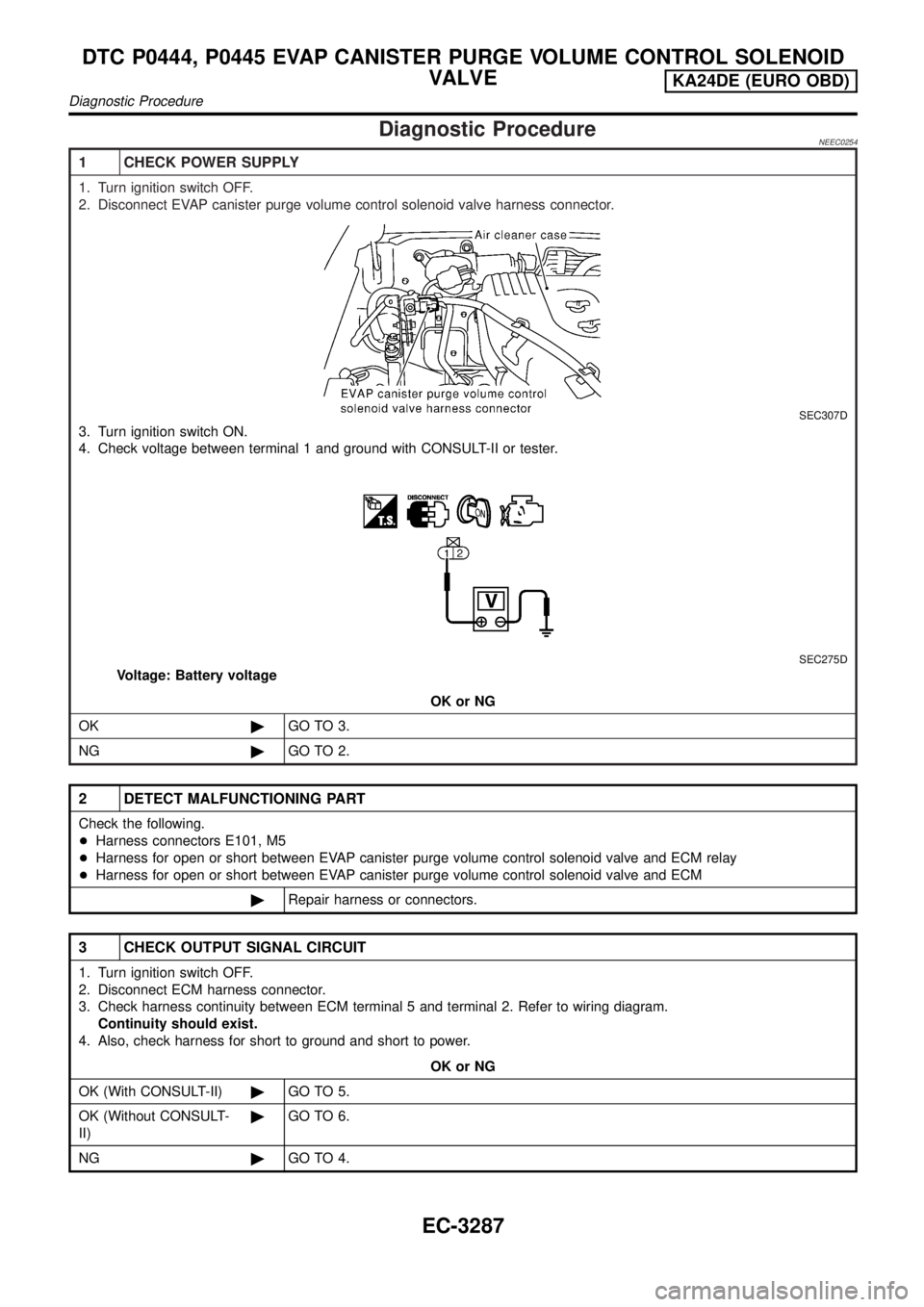
Diagnostic ProcedureNEEC0254
1 CHECK POWER SUPPLY
1. Turn ignition switch OFF.
2. Disconnect EVAP canister purge volume control solenoid valve harness connector.
SEC307D
3. Turn ignition switch ON.
4. Check voltage between terminal 1 and ground with CONSULT-II or tester.
SEC275D
Voltage: Battery voltage
OK or NG
OK©GO TO 3.
NG©GO TO 2.
2 DETECT MALFUNCTIONING PART
Check the following.
+Harness connectors E101, M5
+Harness for open or short between EVAP canister purge volume control solenoid valve and ECM relay
+Harness for open or short between EVAP canister purge volume control solenoid valve and ECM
©Repair harness or connectors.
3 CHECK OUTPUT SIGNAL CIRCUIT
1. Turn ignition switch OFF.
2. Disconnect ECM harness connector.
3. Check harness continuity between ECM terminal 5 and terminal 2. Refer to wiring diagram.
Continuity should exist.
4. Also, check harness for short to ground and short to power.
OK or NG
OK (With CONSULT-II)©GO TO 5.
OK (Without CONSULT-
II)©GO TO 6.
NG©GO TO 4.
DTC P0444, P0445 EVAP CANISTER PURGE VOLUME CONTROL SOLENOID
VALVE
KA24DE (EURO OBD)
Diagnostic Procedure
EC-3287
Page 317 of 1306
Wiring DiagramNEEC0277WITH TACHOMETERNEEC0277S01
GEC250A
DTC P0500 VSSKA24DE (EURO OBD)
Wiring Diagram
EC-3292