Page 149 of 1306
Main Power Supply and Ground Circuit
WIRING DIAGRAMNEEC0047
GEC233A
TROUBLE DIAGNOSIS FOR POWER
SUPPLY
KA24DE (EURO OBD)
Main Power Supply and Ground Circuit
EC-3124
Page 152 of 1306

DIAGNOSTIC PROCEDURE=NEEC0049
1 INSPECTION START
Start engine.
Is engine running?
YesorNo
Ye s©GO TO 9.
No©GO TO 2.
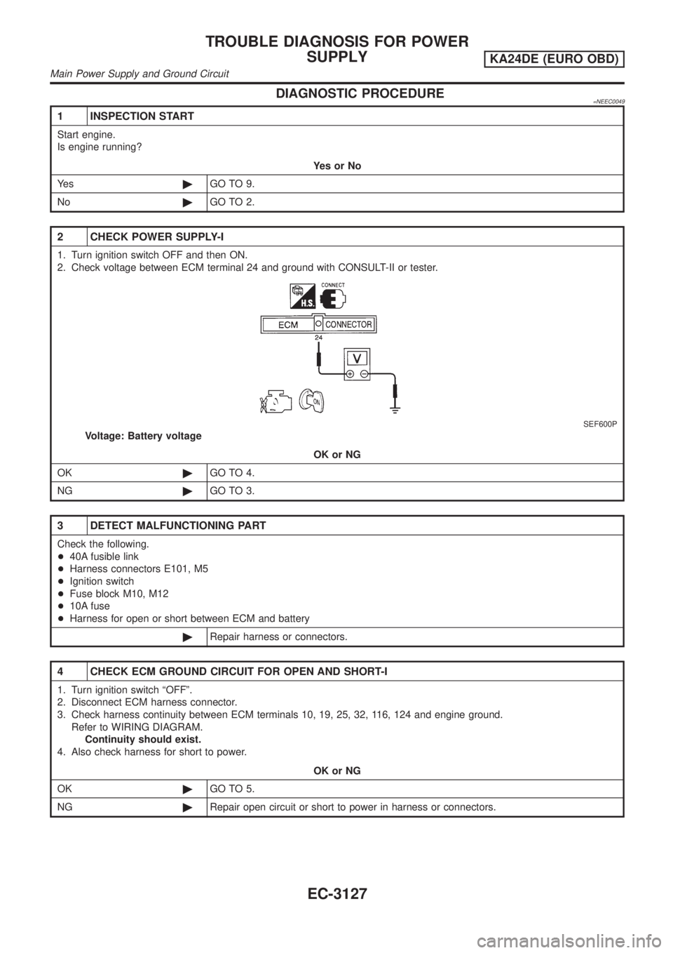
2 CHECK POWER SUPPLY-I
1. Turn ignition switch OFF and then ON.
2. Check voltage between ECM terminal 24 and ground with CONSULT-II or tester.
SEF600P
Voltage: Battery voltage
OK or NG
OK©GO TO 4.
NG©GO TO 3.
3 DETECT MALFUNCTIONING PART
Check the following.
+40A fusible link
+Harness connectors E101, M5
+Ignition switch
+Fuse block M10, M12
+10A fuse
+Harness for open or short between ECM and battery
©Repair harness or connectors.
4 CHECK ECM GROUND CIRCUIT FOR OPEN AND SHORT-I
1. Turn ignition switch ªOFFº.
2. Disconnect ECM harness connector.
3. Check harness continuity between ECM terminals 10, 19, 25, 32, 116, 124 and engine ground.
Refer to WIRING DIAGRAM.
Continuity should exist.
4. Also check harness for short to power.
OK or NG
OK©GO TO 5.
NG©Repair open circuit or short to power in harness or connectors.
TROUBLE DIAGNOSIS FOR POWER
SUPPLY
KA24DE (EURO OBD)
Main Power Supply and Ground Circuit
EC-3127
Page 153 of 1306

5 CHECK POWER SUPPLY-II
1. Disconnect ECM relay.
LEC106A
2. Check voltage between ECM relay terminals 1, 3 and ground with CONSULT-II or tester.
SEC313D
Voltage: Battery voltage
OK or NG
OK©GO TO 7.
NG©GO TO 6.
6 DETECT MALFUNCTIONING PART
Check the following.
+10A fuse
+Harness for open or short between ECM relay and battery
©Repair open circuit or short to ground or short to power in harness or connectors.
7 CHECK OUTPUT SIGNAL CIRCUIT FOR OPEN AND SHORT
1. Check harness continuity between ECM terminal 4 and ECM relay terminal 2. Refer to WIRING DIAGRAM.
Continuity should exist.
2. Also check harness for short to ground and short to power.
OK or NG
OK©Go to ªIGNITION SIGNALº, EC-3361.
NG©GO TO 8.
8 DETECT MALFUNCTIONING PART
Check the following.
+Harness connectors E101, M5
+Harness for open or short between ECM relay and ECM
©Repair open circuit or short to ground or short to power in harness or connectors.
TROUBLE DIAGNOSIS FOR POWER
SUPPLY
KA24DE (EURO OBD)
Main Power Supply and Ground Circuit
EC-3128
Page 160 of 1306
Wiring DiagramNEEC0141
GEC247A
DTC P0031, P0032 HO2S1 HEATERKA24DE (EURO OBD)
Wiring Diagram
EC-3135
Page 165 of 1306
Wiring DiagramNEEC0185
GEC248A
DTC P0037, P0038 HO2S2 HEATERKA24DE (EURO OBD)
Wiring Diagram
EC-3140
Page 171 of 1306
Wiring DiagramNEEC0056
GEC237A
DTC P0101 MAF SENSORKA24DE (EURO OBD)
Wiring Diagram
EC-3146
Page 173 of 1306
4 CHECK POWER SUPPLY
1. Disconnect mass air flow sensor harness connector.
AEC131A
2. Turn ignition switch ON.
3. Check voltage between terminal 3 and ground with CONSULT-II or tester.
AEC691
Voltage: Battery voltage
OK or NG
OK©GO TO 6.
NG©GO TO 5.
5 DETECT MALFUNCTIONING PART
Check the following.
+Harness connectors E101, M5
+Harness for open or short between ECM relay and mass air flow sensor
+Harness for open or short between mass air flow sensor and ECM
©Repair harness or connectors.
6 CHECK GROUND CIRCUIT
1. Turn ignition switch OFF.
2. Disconnect ECM harness connector.
3. Check harness continuity between mass air flow sensor terminal 2 and ECM terminal 55. Refer to wiring diagram.
Continuity should exist.
4. Also check harness for short to ground or short to power.
OK or NG
OK©GO TO 7.
NG©Repair open circuit or short to ground or short to power in harness or connectors.
DTC P0101 MAF SENSORKA24DE (EURO OBD)
Diagnostic Procedure
EC-3148
Page 174 of 1306
7 CHECK INPUT SIGNAL CIRCUIT
1. Check harness continuity between terminal 1 and ECM terminal 54. Refer to wiring diagram.
Continuity should exist.
2. Also check harness for short to ground and short to power.
OK or NG
OK©GO TO 8.
NG©Repair open circuit or short to ground or short to power in harness or connectors.
8 CHECK MASS AIR FLOW SENSOR
1. Reconnect all harness connectors disconnected.
2. Turn ignition switch ON.
3. Start engine and warm it up to normal operating temperature.
4. Check voltage between ECM terminal 54 (mass air flow sensor signal) and ground.
SEF326V
MTBL0326
5. If the voltage is out of specification, disconnect mass air flow sensor harness connector and connect it again. Repeat
above check.
6. If NG, remove mass air flow sensor from air duct. Check hot wire for damage or dust.
SEF893J
OK or NG
OK©GO TO 9.
NG©Replace mass air flow sensor.
DTC P0101 MAF SENSORKA24DE (EURO OBD)
Diagnostic Procedure
EC-3149