Page 110 of 1306

DESCRIPTION FOR WORK FLOWNEEC0037S01
STEP DESCRIPTION
STEP IGet detailed information about the conditions and the environment when the incident/symptom occurred using the
ªDIAGNOSTIC WORK SHEETº, EC-3083.
STEP IIBefore confirming the concern, check and write down (print out using CONSULT-II or Generic Scan Tool) the (1st
trip) Diagnostic Trouble Code (DTC) and the (1st trip) freeze frame data, then erase the code and the data. (Refer
to EC-3060.) The (1st trip) DTC and the (1st trip) freeze frame data can be used when duplicating the incident at
STEP III & IV.
Study the relationship between the cause, specified by (1st trip) DTC, and the symptom described by the cus-
tomer. (The ªSymptom Matrix Chartº will be useful. See EC-3102.)
Also check related service bulletins for information.
STEP IIITry to confirm the symptom and under what conditions the incident occurs.
The ªDIAGNOSTIC WORK SHEETº and the freeze frame data are useful to verify the incident. Connect CON-
SULT-II to the vehicle in DATA MONITOR (AUTO TRIG) mode and check real time diagnosis results.
If the incident cannot be verified, perform²Incident Simulation Tests², refer to GI section.
If the malfunction code is detected, skip STEP IV and perform STEP V.
STEP IVTry to detect the (1st trip) Diagnostic Trouble Code by driving in (or performing) the ªDIAGNOSTIC TROUBLE
CODE CONFIRMATION PROCEDUREº. Check and read the (1st trip) DTC and (1st trip) freeze frame data by
using CONSULT-II or Generic Scan Tool.
During the (1st trip) DTC verification, be sure to connect CONSULT-II to the vehicle in DATA MONITOR (AUTO
TRIG) mode and check real time diagnosis results.
If the incident cannot be verified, perform ªIncident Simulation Testsº, refer to GI section.
In case the ªDIAGNOSTIC TROUBLE CODE CONFIRMATION PROCEDUREº is not available, perform the
ªOVERALL FUNCTION CHECKº instead. The (1st trip) DTC cannot be displayed by this check, however, this sim-
plified ªcheckº is an effective alternative.
The ªNGº result of the ªOVERALL FUNCTION CHECKº is the same as the (1st trip) DTC detection.
STEP VTake the appropriate action based on the results of STEP I through IV.
If the malfunction code is indicated, proceed to TROUBLE DIAGNOSIS FOR DTC PXXXX.
If the normal code is indicated, proceed to the BASIC INSPECTION. (Refer to EC-3086.) If CONSULT-II is
available, perform ªDATA MONITOR (SPEC)º mode with CONSULT-II and proceed to the ªTROUBLE DIAGNOSIS
Ð SPECIFICATION VALUEº, EC-3119. (If malfunction is detected, proceed to ªREPAIR/REPLACEº.) Then perform
inspections according to the Symptom Matrix Chart. (Refer to EC-3102.)
STEP VIIdentify where to begin diagnosis based on the relationship study between symptom and possible causes. Inspect
the system for mechanical binding, loose connectors or wiring damage using (tracing) ªHarness Layoutsº.
Gently shake the related connectors, components or wiring harness with CONSULT-II set in ªDATA MONITOR
(AUTO TRIG)º mode.
Check the voltage of the related ECM terminals or monitor the output data from the related sensors with CON-
SULT-II. Refer to EC-3110.
The ªDIAGNOSTIC PROCEDUREº in EC section contains a description based on open circuit inspection. A short
circuit inspection is also required for the circuit check in the DIAGNOSTIC PROCEDURE. For details, refer to
ªHOW TO PERFORM EFFICIENT DIAGNOSIS FOR AN ELECTRICAL INCIDENTº, ªCircuit Inspectionº, GI section.
Repair or replace the malfunction parts.
STEP VIIOnce you have repaired the circuit or replaced a component, you need to run the engine in the same conditions
and circumstances which resulted in the customer's initial complaint.
Perform the ªDIAGNOSTIC TROUBLE CODE CONFIRMATION PROCEDUREº and confirm the normal code [Diag-
nostic trouble code No. P0000 or 0505] is detected. If the incident is still detected in the final check, perform STEP
VI by using a different method from the previous one.
Before returning the vehicle to the customer, be sure to erase the unnecessary (already fixed) (1st trip) DTC in
ECM. (Refer to EC-3060.)
TROUBLE DIAGNOSIS Ð
INTRODUCTION
KA24DE (EURO OBD)
Work Flow
EC-3085
Page 111 of 1306
Basic InspectionNEEC0038Precaution:
Perform Basic Inspection without electrical or mechanical
loads applied;
+Headlamp switch is OFF,
+Air conditioner switch is OFF,
+Rear window defogger switch is OFF,
+Steering wheel is in the straight-ahead position, etc.
1 INSPECTION START
1. Check service records for any recent repairs that may indicate a related problem, or the current need for scheduled
maintenance.
2. Open engine hood and check the following:
+Harness connectors for improper connections
+Vacuum hoses for splits, kinks, or improper connections
+Wiring for improper connections, pinches, or cuts
SEF142I
With CONSULT-II©GO TO 2.
With GST©GO TO 4.
No tools©GO TO 5.
2 CONNECT CONSULT-II TO THE VEHICLE
Connect ªCONSULT-IIº to the data link connector and select ªENGINEº from the menu. Refer to EC-3070.
SEC305D
©GO TO 3.
TROUBLE DIAGNOSIS Ð BASIC
INSPECTION
KA24DE (EURO OBD)
Basic Inspection
EC-3086
Page 112 of 1306

3 CHECK FI CAM FUNCTION
With CONSULT-II
1. Adjust accelerator wire. Refer to ªAdjust Accelerator Wireº, FE section.
2. Warm up engine to 75ÉC (167ÉF).
3. Stop engine and wait at least 5 seconds, then turn ignition switch ON.
4. Select ªCOOLAN TEMP/Sº in ªDATA MONITORº mode with CONSULT-II.
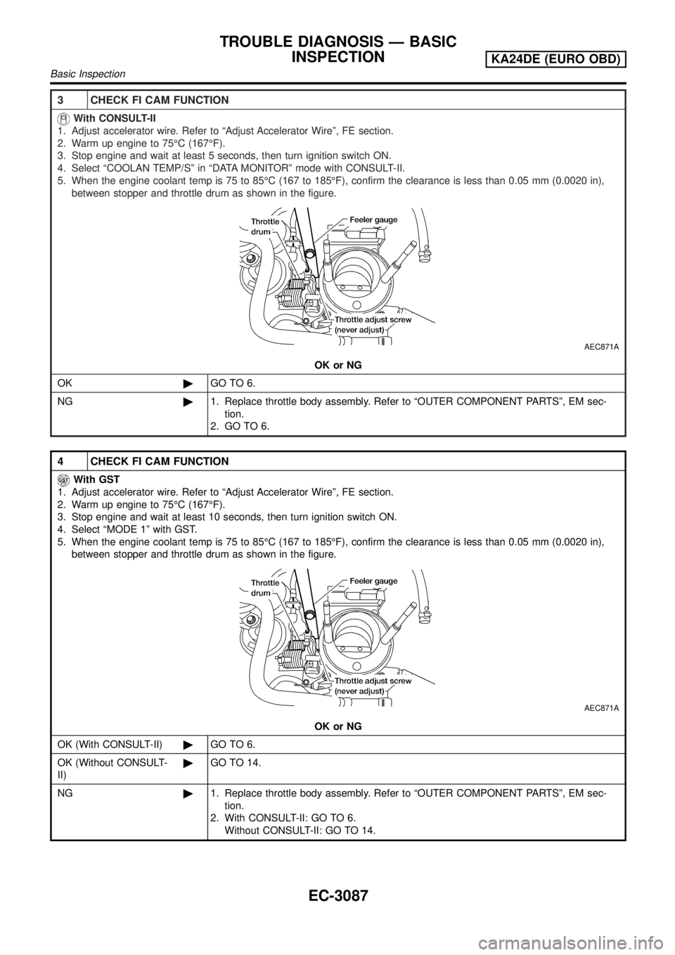
5. When the engine coolant temp is 75 to 85ÉC (167 to 185ÉF), confirm the clearance is less than 0.05 mm (0.0020 in),
between stopper and throttle drum as shown in the figure.
AEC871A
OK or NG
OK©GO TO 6.
NG©1. Replace throttle body assembly. Refer to ªOUTER COMPONENT PARTSº, EM sec-
tion.
2. GO TO 6.
4 CHECK FI CAM FUNCTION
With GST
1. Adjust accelerator wire. Refer to ªAdjust Accelerator Wireº, FE section.
2. Warm up engine to 75ÉC (167ÉF).
3. Stop engine and wait at least 10 seconds, then turn ignition switch ON.
4. Select ªMODE 1º with GST.
5. When the engine coolant temp is 75 to 85ÉC (167 to 185ÉF), confirm the clearance is less than 0.05 mm (0.0020 in),
between stopper and throttle drum as shown in the figure.
AEC871A
OK or NG
OK (With CONSULT-II)©GO TO 6.
OK (Without CONSULT-
II)©GO TO 14.
NG©1. Replace throttle body assembly. Refer to ªOUTER COMPONENT PARTSº, EM sec-
tion.
2. With CONSULT-II: GO TO 6.
Without CONSULT-II: GO TO 14.
TROUBLE DIAGNOSIS Ð BASIC
INSPECTION
KA24DE (EURO OBD)
Basic Inspection
EC-3087
Page 113 of 1306
5 CHECK FI CAM FUNCTION
No Tools
1. Adjust accelerator wire. Refer to ªAdjust Accelerator Wireº, FE section.
2. Disconnect engine coolant temperature sensor harness connector and check resistance as shown in the figure.
SEF536H
3. Warm up engine until the resistance of coolant temperature sensor is 0.26 to 0.39 kW.
4. Turn ignition switch OFF.
5. When engine coolant temperature is 75 to 85ÉC (167 to 185ÉF), with the voltage between 1.10 to 1.36V, make sure that
the clearance is less than 0.05 mm (0.0020 in), between stopper and throttle adjusting screw as shown in figure.
AEC871A
OK or NG
OK©GO TO 14.
NG©1. Replace throttle body assembly. Refer to ªOUTER COMPONENT PARTSº, EM sec-
tion.
2. GO TO 14.
TROUBLE DIAGNOSIS Ð BASIC
INSPECTION
KA24DE (EURO OBD)
Basic Inspection
EC-3088
Page 114 of 1306
6 CHECK IGNITION TIMING
With CONSULT-II
1. Warm up engine to normal operating temperature.
2. Select ªIGNITION TIMING ADJº in ªWORK SUPPORTº mode.
3. Touch ªSTARTº.
PEF546N
4. Check ignition timing at idle using timing light.
SEF320V
Ignition timing:
15ɱ2É BTDC
OK or NG
OK©GO TO 7.
NG©1. Adjust ignition timing by turning distributor. Refer to ªIdle Speed/Ignition Timing/Idle
Mixture Ratio Adjustmentº, EC-3035.
2. GO TO 7.
TROUBLE DIAGNOSIS Ð BASIC
INSPECTION
KA24DE (EURO OBD)
Basic Inspection
EC-3089
Page 116 of 1306
8 CHECK CLOSED THROTTLE POSITION SWITCH IDLE POSITION (CHECK THROTTLE POSITION SEN-
SOR IDLE POSITION)
With CONSULT-II
NOTE:
Always check ignition timing and base idle speed before performing the following.
1. Warm up engine to normal operating temperature.
2. Check FI cam. Refer to procedure 3.
3. Stop engine.
4. Turn ignition switch ON.
5. Select ªDATA MONITORº mode with CONSULT-II.
6. Select ªCLSD THL/P SWº from the menu.
7. Read ªCLSD THL/P SWº signal under the following conditions.
+Insert a 0.1 mm (0.004 in) and 0.3 mm (0.012 in) feeler gauge alternately between the throttle adjust screw (TAS) and
throttle drum as shown in the figure and check the signal.
AEC871A
SEF197Y
ªCLSD THL/P SWº signal should remain ªONº while inserting 0.1 mm (0.004 in) feeler gauge.
ªCLSD THL/P SWº signal should remain ªOFFº while inserting 0.3 mm (0.012 in) feeler gauge.
OK or NG
OK©GO TO 12.
NG©GO TO 9.
TROUBLE DIAGNOSIS Ð BASIC
INSPECTION
KA24DE (EURO OBD)
Basic Inspection
EC-3091
Page 117 of 1306
9 ADJUSTMENT THROTTLE POSITION SENSOR IDLE POSITION-1
With CONSULT-II
NOTE:
+Never adjust throttle adjust screw (TAS).
+Do not touch throttle drum when checking ªCLSD THL/P SWº signal.
Doing so may cause an incorrect adjustment.
1. Warm engine up to normal operating temperature.
2. Check FI cam. Refer to procedure 3.
3. Stop engine.
4. Loosen throttle position sensor fixing bolts.
5. Turn ignition switch ON.
6. Select ªCLSD THL/P SWº in ªDATA MONITORº mode.
7. Insert a 0.1 mm (0.004 in) feeler gauge between throttle adjust screw and throttle drum as shown in the figure.
AEC871A
8. Open throttle valve and then close.
9. Check ªCLSD THL/P SWº signal.
SEF197Y
ªCLSD THL/P SWº signal should remain ªOFFº when the throttle valve is closed.
If it is impossible to adjust closed throttle position switch, replace throttle position sensor.
OK or NG
OK©GO TO 11.
NG©GO TO 10.
TROUBLE DIAGNOSIS Ð BASIC
INSPECTION
KA24DE (EURO OBD)
Basic Inspection
EC-3092
Page 119 of 1306

12 RESET THROTTLE POSITION SENSOR IDLE POSITION MEMORY
With CONSULT-II
NOTE:
Always warm up engine to normal operating temperature. If engine is cool, the throttle position sensor idle posi-
tion memory will not be reset correctly.
1. Start engine.
2. Warm up engine to normal operating temperature.
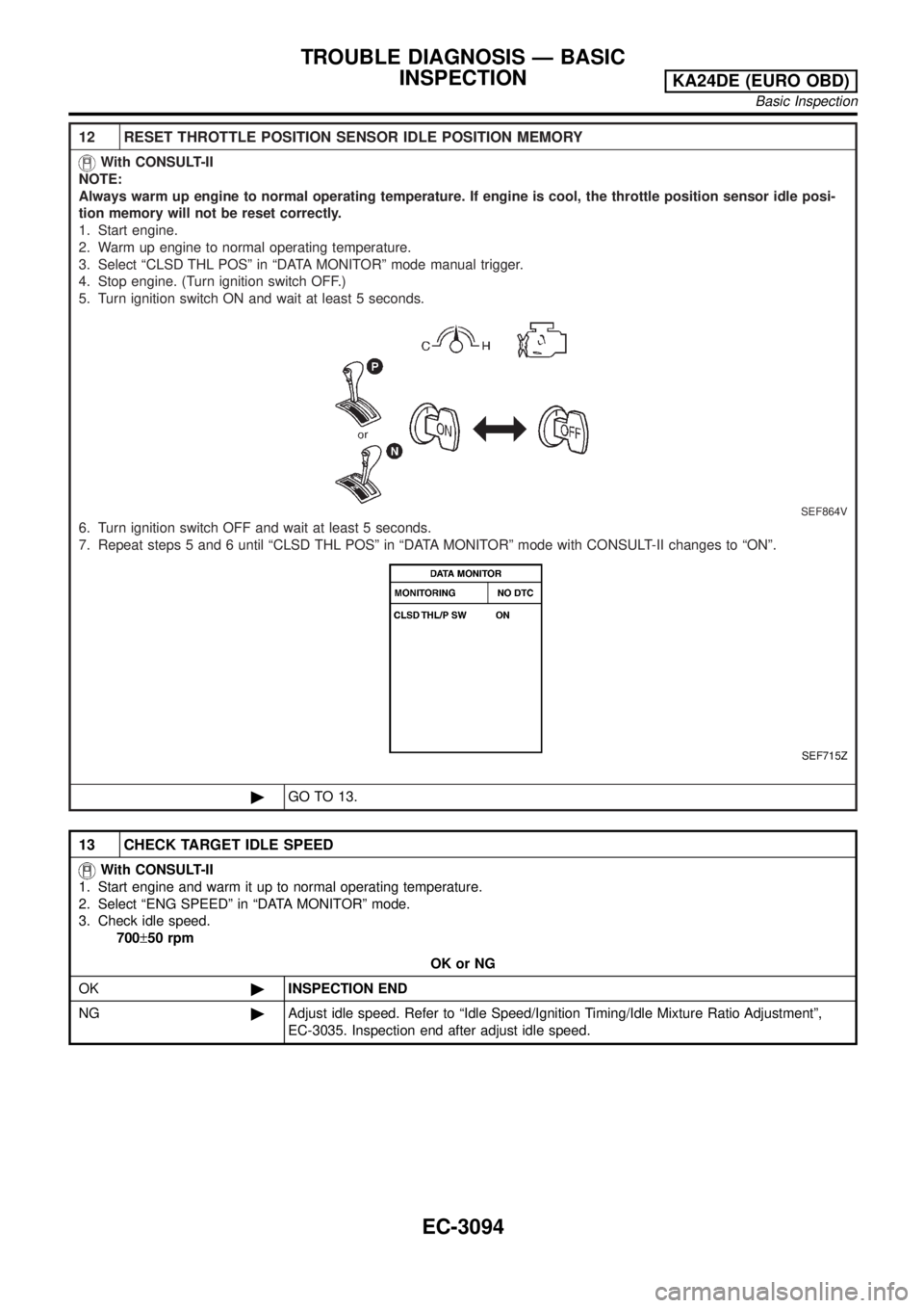
3. Select ªCLSD THL POSº in ªDATA MONITORº mode manual trigger.
4. Stop engine. (Turn ignition switch OFF.)
5. Turn ignition switch ON and wait at least 5 seconds.
SEF864V
6. Turn ignition switch OFF and wait at least 5 seconds.
7. Repeat steps 5 and 6 until ªCLSD THL POSº in ªDATA MONITORº mode with CONSULT-II changes to ªONº.
SEF715Z
©GO TO 13.
13 CHECK TARGET IDLE SPEED
With CONSULT-II
1. Start engine and warm it up to normal operating temperature.
2. Select ªENG SPEEDº in ªDATA MONITORº mode.
3. Check idle speed.
700±50 rpm
OK or NG
OK©INSPECTION END
NG©Adjust idle speed. Refer to ªIdle Speed/Ignition Timing/Idle Mixture Ratio Adjustmentº,
EC-3035. Inspection end after adjust idle speed.
TROUBLE DIAGNOSIS Ð BASIC
INSPECTION
KA24DE (EURO OBD)
Basic Inspection
EC-3094