Page 183 of 1306
8 CHECK MASS AIR FLOW SENSOR
1. Reconnect all harness connectors disconnected.
2. Turn ignition switch ON.
3. Start engine and warm it up to normal operating temperature.
4. Check voltage between ECM terminal 54 (mass air flow sensor signal) and ground.
SEF326V
MTBL0326
5. If the voltage is out of specification, disconnect mass air flow sensor harness connector and connect it again. Repeat
above check.
6. If NG, remove mass air flow sensor from air duct. Check hot wire for damage or dust.
SEF893J
OK or NG
OK©GO TO 9.
NG©Replace mass air flow sensor.
DTC P0102, P0103 MAF SENSORKA24DE (EURO OBD)
Diagnostic Procedure
EC-3158
Page 188 of 1306
Diagnostic ProcedureNEEC0070
1 CHECK POWER SUPPLY
1. Turn ignition switch OFF.
2. Disconnect intake air temperature sensor harness connector.
SEF329V
3. Turn ignition switch ON.
4. Check voltage between terminal 2 and ground with CONSULT-II or tester.
SEC271D
Voltage: Approximately 5V
OK or NG
OK©GO TO 3.
NG©GO TO 2.
2 DETECT MALFUNCTIONING PART
Check the following.
+Harness connectors E101, M5
+Harness for open or short between ECM and intake air temperature sensor
©Repair harness or connectors.
3 CHECK GROUND CIRCUIT
1. Turn ignition switch OFF.
2. Check harness continuity between intake air temperature sensor terminal 1 and engine ground. Refer to the Wiring Dia-
gram.
Continuity should exist.
3. Also check harness for short to power.
OK or NG
OK©GO TO 5.
NG©GO TO 4.
DTC P0112, P0113 IAT SENSORKA24DE (EURO OBD)
Diagnostic Procedure
EC-3163
Page 193 of 1306

Diagnostic ProcedureNEEC0077
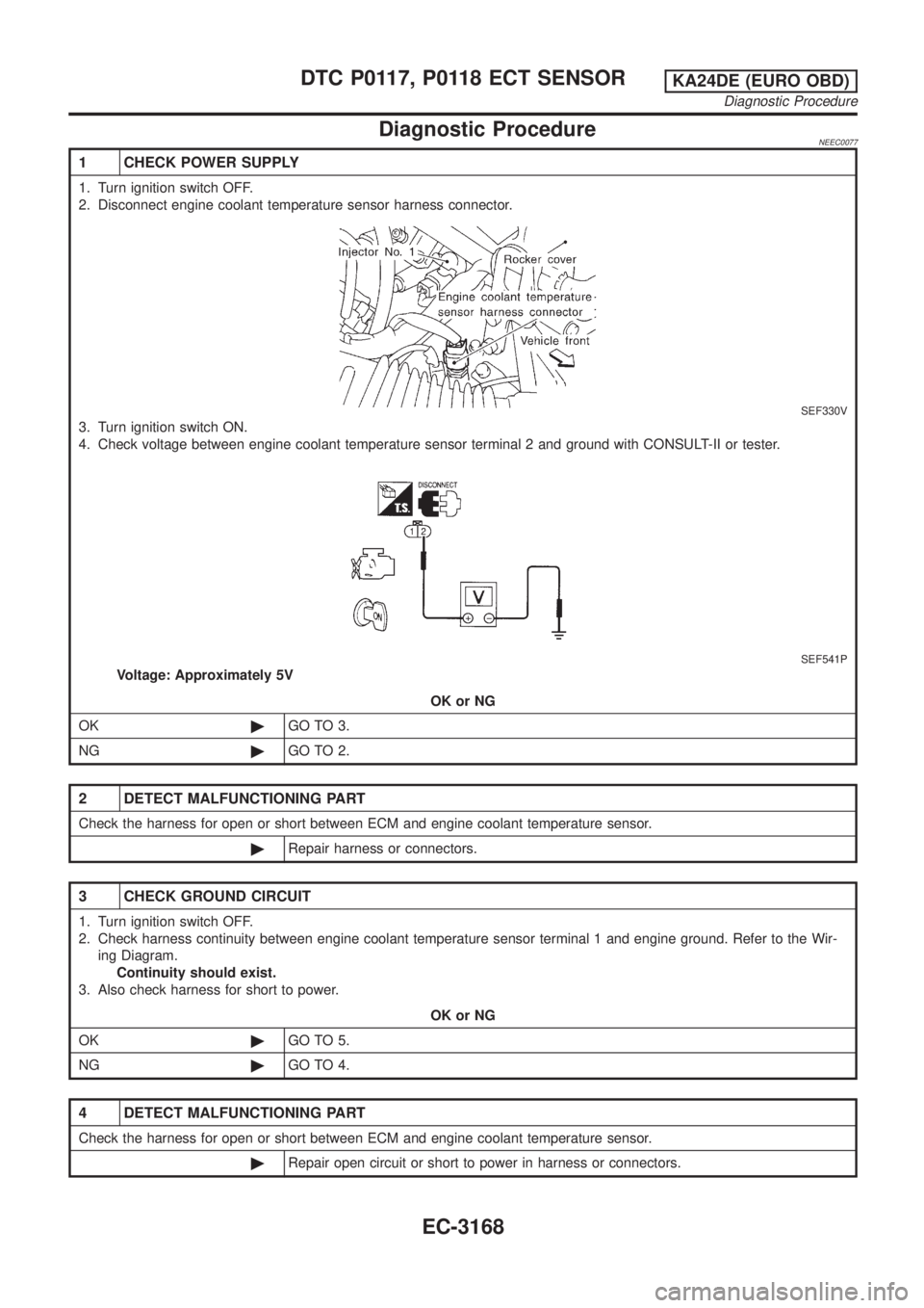
1 CHECK POWER SUPPLY
1. Turn ignition switch OFF.
2. Disconnect engine coolant temperature sensor harness connector.
SEF330V
3. Turn ignition switch ON.
4. Check voltage between engine coolant temperature sensor terminal 2 and ground with CONSULT-II or tester.
SEF541P
Voltage: Approximately 5V
OK or NG
OK©GO TO 3.
NG©GO TO 2.
2 DETECT MALFUNCTIONING PART
Check the harness for open or short between ECM and engine coolant temperature sensor.
©Repair harness or connectors.
3 CHECK GROUND CIRCUIT
1. Turn ignition switch OFF.
2. Check harness continuity between engine coolant temperature sensor terminal 1 and engine ground. Refer to the Wir-
ing Diagram.
Continuity should exist.
3. Also check harness for short to power.
OK or NG
OK©GO TO 5.
NG©GO TO 4.
4 DETECT MALFUNCTIONING PART
Check the harness for open or short between ECM and engine coolant temperature sensor.
©Repair open circuit or short to power in harness or connectors.
DTC P0117, P0118 ECT SENSORKA24DE (EURO OBD)
Diagnostic Procedure
EC-3168
Page 194 of 1306
5 CHECK ENGINE COOLANT TEMPERATURE SENSOR
Check resistance as shown in the figure.
SEF152P
MTBL0285
SEF012P
OK or NG
OK©GO TO 6.
NG©Replace engine coolant temperature sensor.
6 CHECK INTERMITTENT INCIDENT
Perform ªTROUBLE DIAGNOSIS FOR INTERMITTENT INCIDENTº, EC-3123.
©INSPECTION END
DTC P0117, P0118 ECT SENSORKA24DE (EURO OBD)
Diagnostic Procedure
EC-3169
Page 196 of 1306

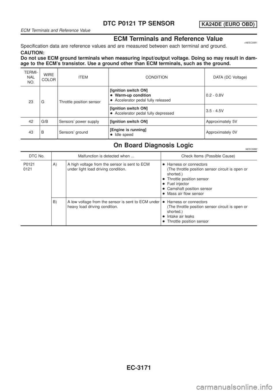
ECM Terminals and Reference Value=NEEC0081Specification data are reference values and are measured between each terminal and ground.
CAUTION:
Do not use ECM ground terminals when measuring input/output voltage. Doing so may result in dam-
age to the ECM's transistor. Use a ground other than ECM terminals, such as the ground.
TERMI-
NAL
NO.WIRE
COLORITEM CONDITION DATA (DC Voltage)
23 G Throttle position sensor[Ignition switch ON]
+Warm-up condition
+Accelerator pedal fully released0.2 - 0.8V
[Ignition switch ON]
+Accelerator pedal fully depressed3.5 - 4.5V
42 G/B Sensors' power supply[Ignition switch ON]Approximately 5V
43 B Sensors' ground[Engine is running]
+Idle speedApproximately 0V
On Board Diagnosis LogicNEEC0082
DTC No. Malfunction is detected when ... Check Items (Possible Cause)
P0121
0121A) A high voltage from the sensor is sent to ECM
under light load driving condition.+Harness or connectors
(The throttle position sensor circuit is open or
shorted.)
+Throttle position sensor
+Fuel injector
+Camshaft position sensor
+Mass air flow sensor
B) A low voltage from the sensor is sent to ECM under
heavy load driving condition.+Harness or connectors
(The throttle position sensor circuit is open or
shorted.)
+Intake air leaks
+Throttle position sensor
DTC P0121 TP SENSORKA24DE (EURO OBD)
ECM Terminals and Reference Value
EC-3171
Page 197 of 1306

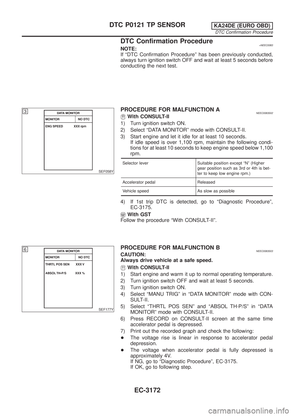
DTC Confirmation Procedure=NEEC0083NOTE:
If ªDTC Confirmation Procedureº has been previously conducted,
always turn ignition switch OFF and wait at least 5 seconds before
conducting the next test.
SEF058Y
PROCEDURE FOR MALFUNCTION ANEEC0083S02With CONSULT-II
1) Turn ignition switch ON.
2) Select ªDATA MONITORº mode with CONSULT-II.
3) Start engine and let it idle for at least 10 seconds.
If idle speed is over 1,100 rpm, maintain the following condi-
tions for at least 10 seconds to keep engine speed below 1,100
rpm.
Selector lever Suitable position except ªNº (Higher
gear position such as 3rd or 4th is bet-
ter to keep low engine rpm.)
Accelerator pedal Released
Vehicle speed As slow as possible
4) If 1st trip DTC is detected, go to ªDiagnostic Procedureº,
EC-3175.
With GST
Follow the procedure ªWith CONSULT-IIº.
SEF177Y
PROCEDURE FOR MALFUNCTION BNEEC0083S03CAUTION:
Always drive vehicle at a safe speed.
With CONSULT-II
1) Start engine and warm it up to normal operating temperature.
2) Turn ignition switch OFF and wait at least 5 seconds.
3) Turn ignition switch ON.
4) Select ªMANU TRIGº in ªDATA MONITORº mode with CON-
SULT-II.
5) Select ªTHRTL POS SENº and ªABSOL TH´P/Sº in ªDATA
MONITORº mode with CONSULT-II.
6) Press RECORD on CONSULT-II screen at the same time
accelerator pedal is depressed.
7) Print out the recorded graph and check the following:
+The voltage rise is linear in response to accelerator pedal
depression.
+The voltage when accelerator pedal is fully depressed is
approximately 4V.
If NG, go to ªDiagnostic Procedureº, EC-3175.
If OK, go to following step.
DTC P0121 TP SENSORKA24DE (EURO OBD)
DTC Confirmation Procedure
EC-3172
Page 200 of 1306
Diagnostic ProcedureNEEC0085
1 INSPECTION START
Which malfunction A or B is duplicated?
MTBL1307
TypeAorB
Type A©GO TO 4.
Type B©GO TO 2.
2 ADJUST THROTTLE POSITION SENSOR
1. Check the following items. Refer to ªBasic Inspectionº, EC-3086.
MTBL1315
OK or NG
OK©GO TO 3.
3 CHECK INTAKE SYSTEM
Check the following for connection.
+Air duct
+Air cleaner
+Vacuum hoses
+Intake air passage between air duct to intake manifold collector
OK or NG
OK©GO TO 4.
NG©Reconnect the parts.
4 RETIGHTEN GROUND SCREWS
1. Turn ignition switch OFF.
2. Loosen and retighten engine ground screws.
SEC309D
©GO TO 5.
DTC P0121 TP SENSORKA24DE (EURO OBD)
Diagnostic Procedure
EC-3175
Page 201 of 1306
5 CHECK POWER SUPPLY
1. Disconnect throttle position sensor harness connector.
SEF265S
2. Turn ignition switch ON.
3. Check voltage between terminal 1 and ground with CONSULT-II or tester.
SEF564P
Voltage: Approximately 5V
OK or NG
OK©GO TO 6.
NG©Repair harness or connectors.
6 CHECK GROUND CIRCUIT
1. Turn ignition switch OFF.
2. Check harness continuity between throttle position sensor terminal 3 and engine ground. Refer to the Wiring Diagram.
SEF565P
Continuity should exist.
3. Also check harness for short to power.
OK or NG
OK©GO TO 8.
NG©GO TO 7.
DTC P0121 TP SENSORKA24DE (EURO OBD)
Diagnostic Procedure
EC-3176