2001 NISSAN PICK-UP sensor
[x] Cancel search: sensorPage 581 of 1306
Description
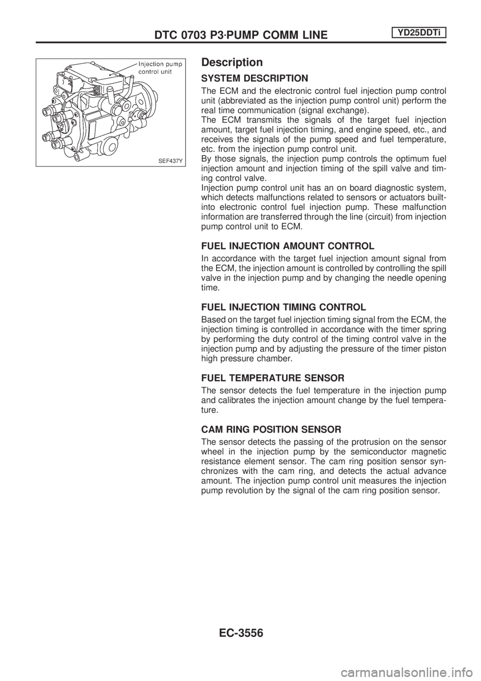
SYSTEM DESCRIPTION
The ECM and the electronic control fuel injection pump control
unit (abbreviated as the injection pump control unit) perform the
real time communication (signal exchange).
The ECM transmits the signals of the target fuel injection
amount, target fuel injection timing, and engine speed, etc., and
receives the signals of the pump speed and fuel temperature,
etc. from the injection pump control unit.
By those signals, the injection pump controls the optimum fuel
injection amount and injection timing of the spill valve and tim-
ing control valve.
Injection pump control unit has an on board diagnostic system,
which detects malfunctions related to sensors or actuators built-
into electronic control fuel injection pump. These malfunction
information are transferred through the line (circuit) from injection
pump control unit to ECM.
FUEL INJECTION AMOUNT CONTROL
In accordance with the target fuel injection amount signal from
the ECM, the injection amount is controlled by controlling the spill
valve in the injection pump and by changing the needle opening
time.
FUEL INJECTION TIMING CONTROL
Based on the target fuel injection timing signal from the ECM, the
injection timing is controlled in accordance with the timer spring
by performing the duty control of the timing control valve in the
injection pump and by adjusting the pressure of the timer piston
high pressure chamber.
FUEL TEMPERATURE SENSOR
The sensor detects the fuel temperature in the injection pump
and calibrates the injection amount change by the fuel tempera-
ture.
CAM RING POSITION SENSOR
The sensor detects the passing of the protrusion on the sensor
wheel in the injection pump by the semiconductor magnetic
resistance element sensor. The cam ring position sensor syn-
chronizes with the cam ring, and detects the actual advance
amount. The injection pump control unit measures the injection
pump revolution by the signal of the cam ring position sensor.
SEF437Y
DTC 0703 P3zPUMP COMM LINEYD25DDTi
EC-3556
Page 588 of 1306
Description
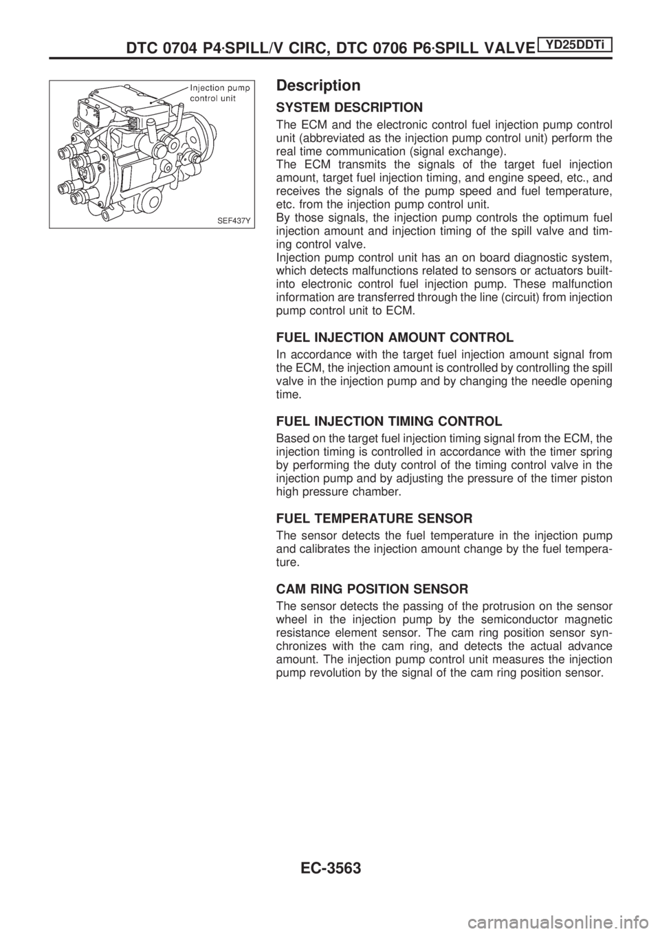
SYSTEM DESCRIPTION
The ECM and the electronic control fuel injection pump control
unit (abbreviated as the injection pump control unit) perform the
real time communication (signal exchange).
The ECM transmits the signals of the target fuel injection
amount, target fuel injection timing, and engine speed, etc., and
receives the signals of the pump speed and fuel temperature,
etc. from the injection pump control unit.
By those signals, the injection pump controls the optimum fuel
injection amount and injection timing of the spill valve and tim-
ing control valve.
Injection pump control unit has an on board diagnostic system,
which detects malfunctions related to sensors or actuators built-
into electronic control fuel injection pump. These malfunction
information are transferred through the line (circuit) from injection
pump control unit to ECM.
FUEL INJECTION AMOUNT CONTROL
In accordance with the target fuel injection amount signal from
the ECM, the injection amount is controlled by controlling the spill
valve in the injection pump and by changing the needle opening
time.
FUEL INJECTION TIMING CONTROL
Based on the target fuel injection timing signal from the ECM, the
injection timing is controlled in accordance with the timer spring
by performing the duty control of the timing control valve in the
injection pump and by adjusting the pressure of the timer piston
high pressure chamber.
FUEL TEMPERATURE SENSOR
The sensor detects the fuel temperature in the injection pump
and calibrates the injection amount change by the fuel tempera-
ture.
CAM RING POSITION SENSOR
The sensor detects the passing of the protrusion on the sensor
wheel in the injection pump by the semiconductor magnetic
resistance element sensor. The cam ring position sensor syn-
chronizes with the cam ring, and detects the actual advance
amount. The injection pump control unit measures the injection
pump revolution by the signal of the cam ring position sensor.
SEF437Y
DTC 0704 P4zSPILL/V CIRC, DTC 0706 P6zSPILL VALVEYD25DDTi
EC-3563
Page 595 of 1306
Description
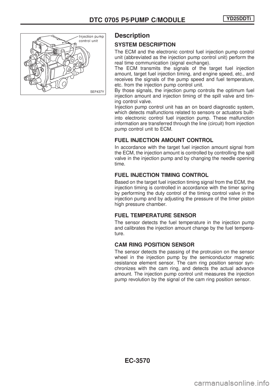
SYSTEM DESCRIPTION
The ECM and the electronic control fuel injection pump control
unit (abbreviated as the injection pump control unit) perform the
real time communication (signal exchange).
The ECM transmits the signals of the target fuel injection
amount, target fuel injection timing, and engine speed, etc., and
receives the signals of the pump speed and fuel temperature,
etc. from the injection pump control unit.
By those signals, the injection pump controls the optimum fuel
injection amount and injection timing of the spill valve and tim-
ing control valve.
Injection pump control unit has an on board diagnostic system,
which detects malfunctions related to sensors or actuators built-
into electronic control fuel injection pump. These malfunction
information are transferred through the line (circuit) from injection
pump control unit to ECM.
FUEL INJECTION AMOUNT CONTROL
In accordance with the target fuel injection amount signal from
the ECM, the injection amount is controlled by controlling the spill
valve in the injection pump and by changing the needle opening
time.
FUEL INJECTION TIMING CONTROL
Based on the target fuel injection timing signal from the ECM, the
injection timing is controlled in accordance with the timer spring
by performing the duty control of the timing control valve in the
injection pump and by adjusting the pressure of the timer piston
high pressure chamber.
FUEL TEMPERATURE SENSOR
The sensor detects the fuel temperature in the injection pump
and calibrates the injection amount change by the fuel tempera-
ture.
CAM RING POSITION SENSOR
The sensor detects the passing of the protrusion on the sensor
wheel in the injection pump by the semiconductor magnetic
resistance element sensor. The cam ring position sensor syn-
chronizes with the cam ring, and detects the actual advance
amount. The injection pump control unit measures the injection
pump revolution by the signal of the cam ring position sensor.
SEF437Y
DTC 0705 P5zPUMP C/MODULEYD25DDTi
EC-3570
Page 598 of 1306
Description
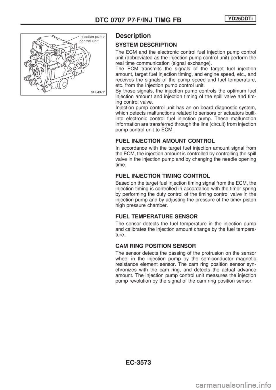
SYSTEM DESCRIPTION
The ECM and the electronic control fuel injection pump control
unit (abbreviated as the injection pump control unit) perform the
real time communication (signal exchange).
The ECM transmits the signals of the target fuel injection
amount, target fuel injection timing, and engine speed, etc., and
receives the signals of the pump speed and fuel temperature,
etc. from the injection pump control unit.
By those signals, the injection pump controls the optimum fuel
injection amount and injection timing of the spill valve and tim-
ing control valve.
Injection pump control unit has an on board diagnostic system,
which detects malfunctions related to sensors or actuators built-
into electronic control fuel injection pump. These malfunction
information are transferred through the line (circuit) from injection
pump control unit to ECM.
FUEL INJECTION AMOUNT CONTROL
In accordance with the target fuel injection amount signal from
the ECM, the injection amount is controlled by controlling the spill
valve in the injection pump and by changing the needle opening
time.
FUEL INJECTION TIMING CONTROL
Based on the target fuel injection timing signal from the ECM, the
injection timing is controlled in accordance with the timer spring
by performing the duty control of the timing control valve in the
injection pump and by adjusting the pressure of the timer piston
high pressure chamber.
FUEL TEMPERATURE SENSOR
The sensor detects the fuel temperature in the injection pump
and calibrates the injection amount change by the fuel tempera-
ture.
CAM RING POSITION SENSOR
The sensor detects the passing of the protrusion on the sensor
wheel in the injection pump by the semiconductor magnetic
resistance element sensor. The cam ring position sensor syn-
chronizes with the cam ring, and detects the actual advance
amount. The injection pump control unit measures the injection
pump revolution by the signal of the cam ring position sensor.
SEF437Y
DTC 0707 P7zF/INJ TIMG FBYD25DDTi
EC-3573
Page 606 of 1306
Description
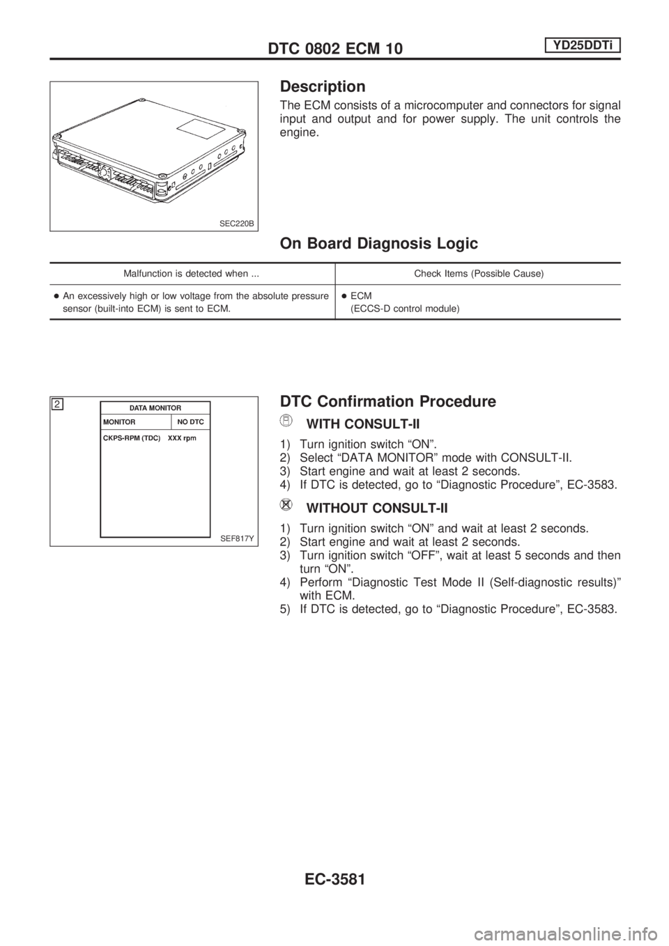
The ECM consists of a microcomputer and connectors for signal
input and output and for power supply. The unit controls the
engine.
On Board Diagnosis Logic
Malfunction is detected when ... Check Items (Possible Cause)
+An excessively high or low voltage from the absolute pressure
sensor (built-into ECM) is sent to ECM.+ECM
(ECCS-D control module)
DTC Confirmation Procedure
WITH CONSULT-II
1) Turn ignition switch ªONº.
2) Select ªDATA MONITORº mode with CONSULT-II.
3) Start engine and wait at least 2 seconds.
4) If DTC is detected, go to ªDiagnostic Procedureº, EC-3583.
WITHOUT CONSULT-II
1) Turn ignition switch ªONº and wait at least 2 seconds.
2) Start engine and wait at least 2 seconds.
3) Turn ignition switch ªOFFº, wait at least 5 seconds and then
turn ªONº.
4) Perform ªDiagnostic Test Mode II (Self-diagnostic results)º
with ECM.
5) If DTC is detected, go to ªDiagnostic Procedureº, EC-3583.
SEC220B
SEF817Y
DTC 0802 ECM 10YD25DDTi
EC-3581
Page 607 of 1306
Diagnostic Procedure
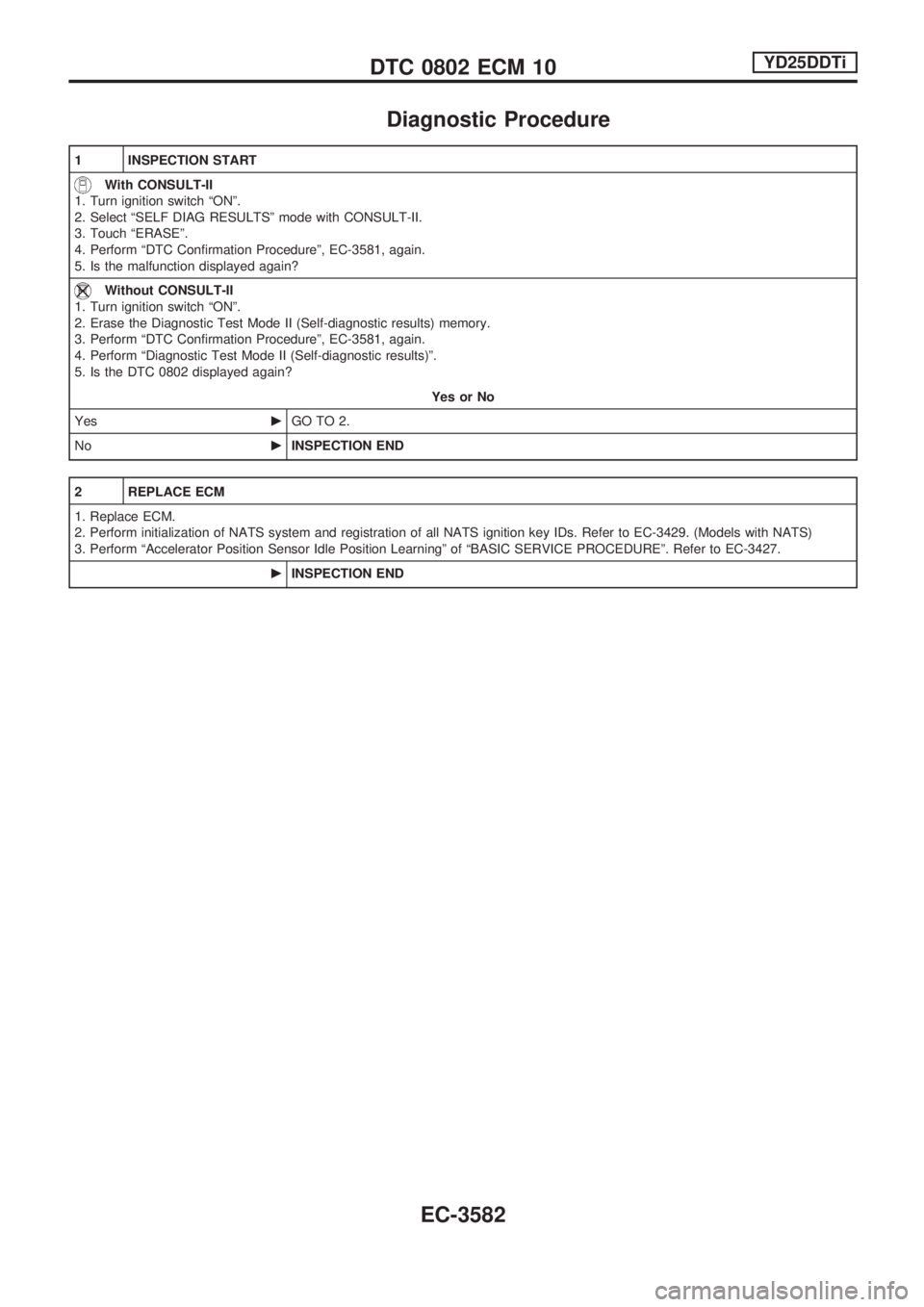
1 INSPECTION START
With CONSULT-II
1. Turn ignition switch ªONº.
2. Select ªSELF DIAG RESULTSº mode with CONSULT-II.
3. Touch ªERASEº.
4. Perform ªDTC Confirmation Procedureº, EC-3581, again.
5. Is the malfunction displayed again?
Without CONSULT-II
1. Turn ignition switch ªONº.
2. Erase the Diagnostic Test Mode II (Self-diagnostic results) memory.
3. Perform ªDTC Confirmation Procedureº, EC-3581, again.
4. Perform ªDiagnostic Test Mode II (Self-diagnostic results)º.
5. Is the DTC 0802 displayed again?
Yes or No
YescGO TO 2.
NocINSPECTION END
2 REPLACE ECM
1. Replace ECM.
2. Perform initialization of NATS system and registration of all NATS ignition key IDs. Refer to EC-3429. (Models with NATS)
3. Perform ªAccelerator Position Sensor Idle Position Learningº of ªBASIC SERVICE PROCEDUREº. Refer to EC-3427.
cINSPECTION END
DTC 0802 ECM 10YD25DDTi
EC-3582
Page 609 of 1306
Diagnostic Procedure
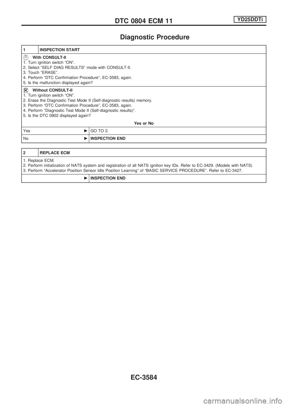
1 INSPECTION START
With CONSULT-II
1. Turn ignition switch ªONº.
2. Select ªSELF DIAG RESULTSº mode with CONSULT-II.
3. Touch ªERASEº.
4. Perform ªDTC Confirmation Procedureº, EC-3583, again.
5. Is the malfunction displayed again?
Without CONSULT-II
1. Turn ignition switch ªONº.
2. Erase the Diagnostic Test Mode II (Self-diagnostic results) memory.
3. Perform ªDTC Confirmation Procedureº, EC-3583, again.
4. Perform ªDiagnostic Test Mode II (Self-diagnostic results)º.
5. Is the DTC 0802 displayed again?
Yes or No
YescGO TO 2.
NocINSPECTION END
2 REPLACE ECM
1. Replace ECM.
2. Perform initialization of NATS system and registration of all NATS ignition key IDs. Refer to EC-3429. (Models with NATS)
3. Perform ªAccelerator Position Sensor Idle Position Learningº of ªBASIC SERVICE PROCEDUREº. Refer to EC-3427.
cINSPECTION END
DTC 0804 ECM 11YD25DDTi
EC-3584
Page 624 of 1306
Diagnostic Procedure
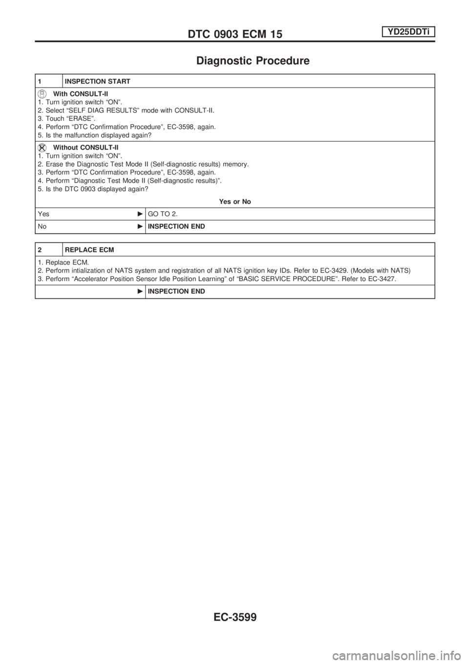
1 INSPECTION START
With CONSULT-II
1. Turn ignition switch ªONº.
2. Select ªSELF DIAG RESULTSº mode with CONSULT-II.
3. Touch ªERASEº.
4. Perform ªDTC Confirmation Procedureº, EC-3598, again.
5. Is the malfunction displayed again?
Without CONSULT-II
1. Turn ignition switch ªONº.
2. Erase the Diagnostic Test Mode II (Self-diagnostic results) memory.
3. Perform ªDTC Confirmation Procedureº, EC-3598, again.
4. Perform ªDiagnostic Test Mode II (Self-diagnostic results)º.
5. Is the DTC 0903 displayed again?
Yes or No
YescGO TO 2.
NocINSPECTION END
2 REPLACE ECM
1. Replace ECM.
2. Perform intialization of NATS system and registration of all NATS ignition key IDs. Refer to EC-3429. (Models with NATS)
3. Perform ªAccelerator Position Sensor Idle Position Learningº of ªBASIC SERVICE PROCEDUREº. Refer to EC-3427.
cINSPECTION END
DTC 0903 ECM 15YD25DDTi
EC-3599