Page 625 of 1306
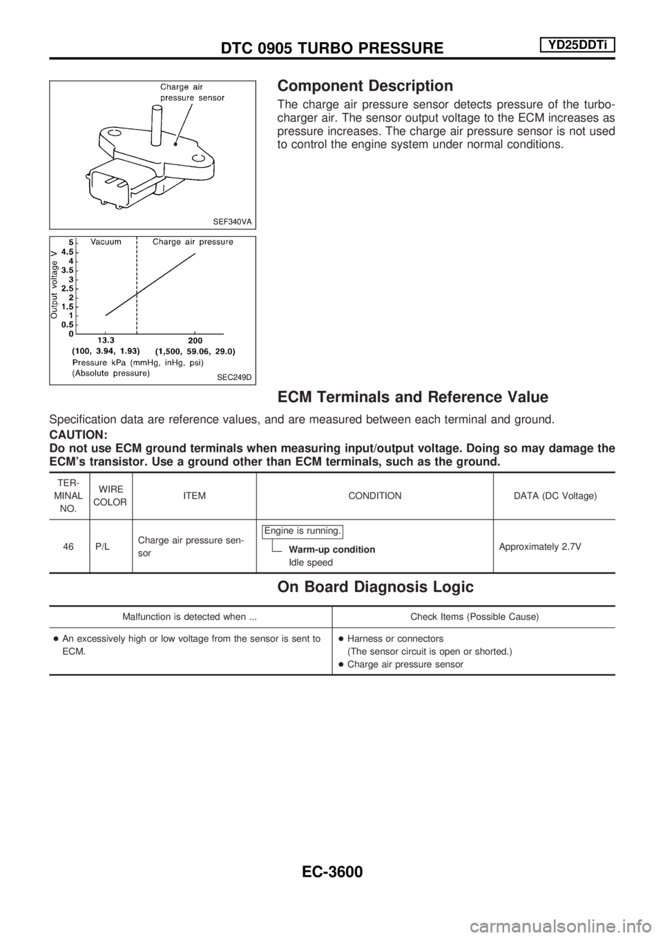
Component Description
The charge air pressure sensor detects pressure of the turbo-
charger air. The sensor output voltage to the ECM increases as
pressure increases. The charge air pressure sensor is not used
to control the engine system under normal conditions.
ECM Terminals and Reference Value
Specification data are reference values, and are measured between each terminal and ground.
CAUTION:
Do not use ECM ground terminals when measuring input/output voltage. Doing so may damage the
ECM's transistor. Use a ground other than ECM terminals, such as the ground.
TER-
MINAL
NO.WIRE
COLORITEM CONDITION DATA (DC Voltage)
46 P/LCharge air pressure sen-
sorEngine is running.
Warm-up condition
Idle speedApproximately 2.7V
On Board Diagnosis Logic
Malfunction is detected when ... Check Items (Possible Cause)
+An excessively high or low voltage from the sensor is sent to
ECM.+Harness or connectors
(The sensor circuit is open or shorted.)
+Charge air pressure sensor
SEF340VA
SEC249D
DTC 0905 TURBO PRESSUREYD25DDTi
EC-3600
Page 628 of 1306
Diagnostic Procedure
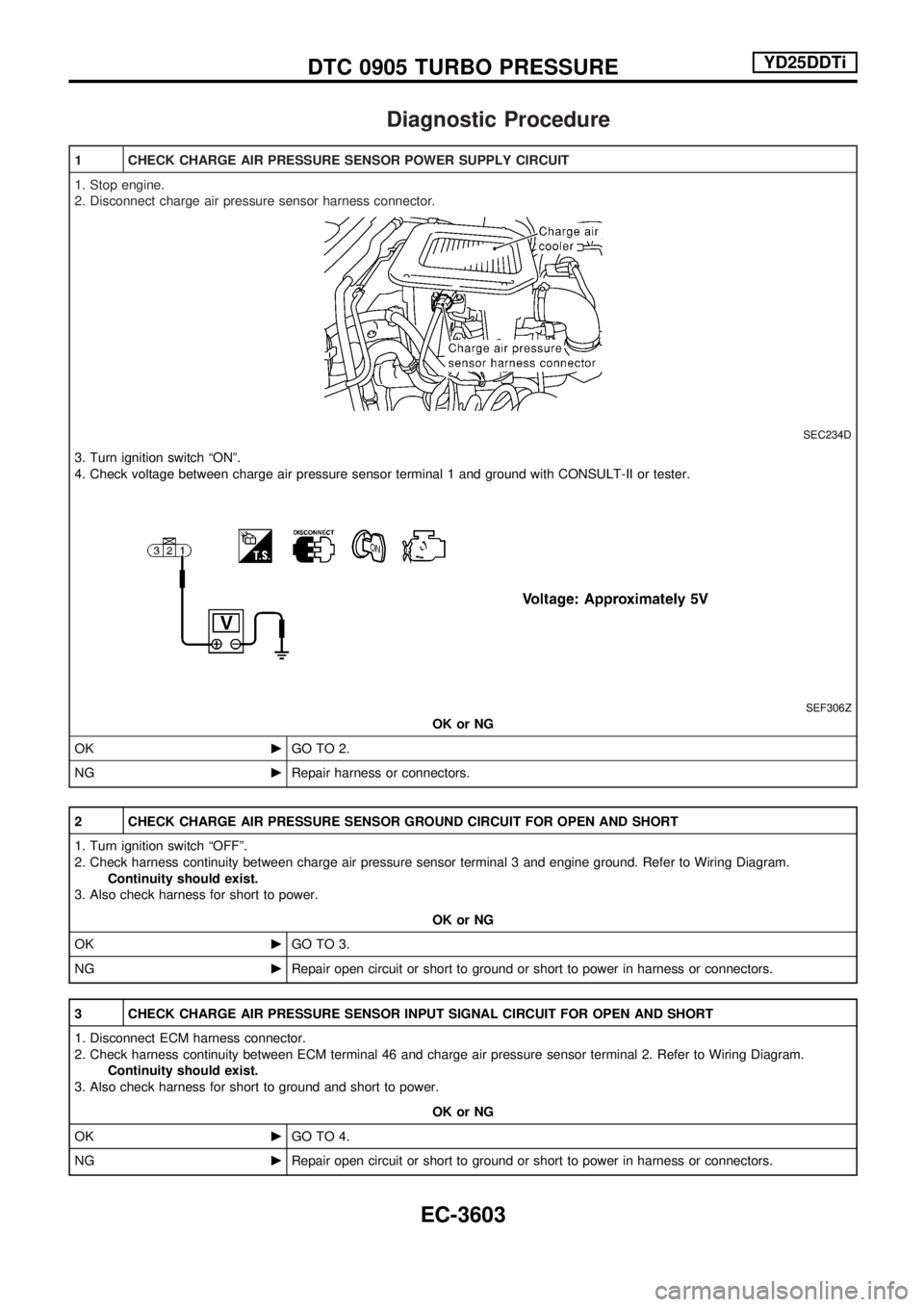
1 CHECK CHARGE AIR PRESSURE SENSOR POWER SUPPLY CIRCUIT
1. Stop engine.
2. Disconnect charge air pressure sensor harness connector.
SEC234D
3. Turn ignition switch ªONº.
4. Check voltage between charge air pressure sensor terminal 1 and ground with CONSULT-II or tester.
SEF306Z
OK or NG
OKcGO TO 2.
NGcRepair harness or connectors.
2 CHECK CHARGE AIR PRESSURE SENSOR GROUND CIRCUIT FOR OPEN AND SHORT
1. Turn ignition switch ªOFFº.
2. Check harness continuity between charge air pressure sensor terminal 3 and engine ground. Refer to Wiring Diagram.
Continuity should exist.
3. Also check harness for short to power.
OK or NG
OKcGO TO 3.
NGcRepair open circuit or short to ground or short to power in harness or connectors.
3 CHECK CHARGE AIR PRESSURE SENSOR INPUT SIGNAL CIRCUIT FOR OPEN AND SHORT
1. Disconnect ECM harness connector.
2. Check harness continuity between ECM terminal 46 and charge air pressure sensor terminal 2. Refer to Wiring Diagram.
Continuity should exist.
3. Also check harness for short to ground and short to power.
OK or NG
OKcGO TO 4.
NGcRepair open circuit or short to ground or short to power in harness or connectors.
DTC 0905 TURBO PRESSUREYD25DDTi
EC-3603
Page 629 of 1306
4 CHECK CHARGE AIR PRESSURE SENSOR
1. Remove charge air pressure sensor with its harness connector connected.
2. Turn ignition switch ªONº.
3. Use pump to apply pressure to charge air pressure sensor as shown in the figure.
CAUTION:
+Always calibrate the pressure pump gauge when using it.
+Inspection should be done at room temperature [10 - 30ÉC (50 - 86ÉF)].
4. Check the output voltage between charge air pressure sensor terminal 2 and engine ground.
SEF449Z
OK or NG
OKcGO TO 5.
NGcReplace charge air pressure sensor.
5 CHECK INTERMITTENT INCIDENT
Refer to ªTROUBLE DIAGNOSIS FOR INTERMITTENT INCIDENTº, EC-3469.
cINSPECTION END
DTC 0905 TURBO PRESSUREYD25DDTi
Diagnostic Procedure (Cont'd)
EC-3604
Page 630 of 1306
Description
SYSTEM DESCRIPTION
Sensor Input Signal to ECM ECM Function Actuator
Electronic controlled fuel injection pump Fuel injection signal
EGR volume
controlEGR volume control valve Crankshaft position sensor (TDC) Engine speed
Vehicle speed sensor Vehicle speed
Engine coolant temperature sensor Engine coolant temperature
Ignition switch Start signal
Accelerator position sensor Accelerator position
Battery Battery voltage
Air conditioner switch Air conditioner operation
PNP switch Park/Neutral position signal
Barometric pressure sensor (Built into
ECM)Barometric pressure
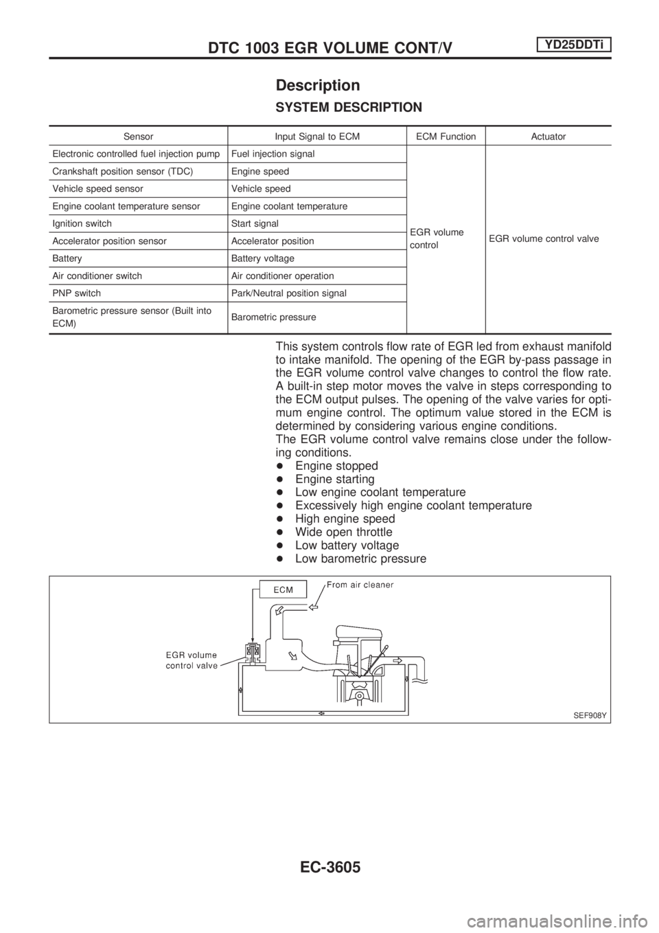
This system controls flow rate of EGR led from exhaust manifold
to intake manifold. The opening of the EGR by-pass passage in
the EGR volume control valve changes to control the flow rate.
A built-in step motor moves the valve in steps corresponding to
the ECM output pulses. The opening of the valve varies for opti-
mum engine control. The optimum value stored in the ECM is
determined by considering various engine conditions.
The EGR volume control valve remains close under the follow-
ing conditions.
+Engine stopped
+Engine starting
+Low engine coolant temperature
+Excessively high engine coolant temperature
+High engine speed
+Wide open throttle
+Low battery voltage
+Low barometric pressure
SEF908Y
DTC 1003 EGR VOLUME CONT/VYD25DDTi
EC-3605
Page 639 of 1306
Description
SYSTEM DESCRIPTION
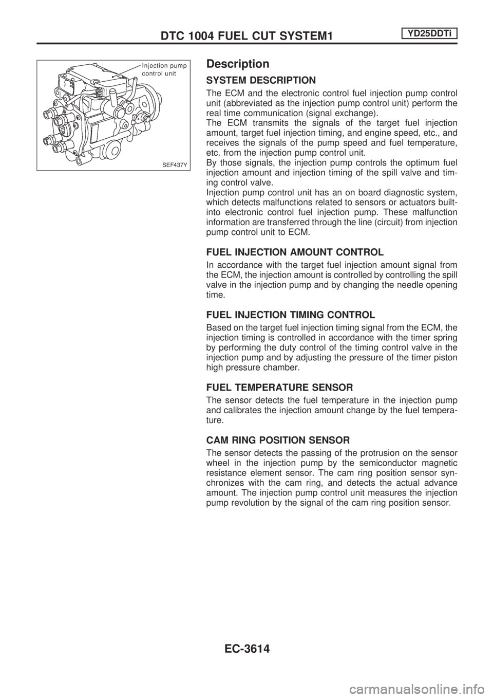
The ECM and the electronic control fuel injection pump control
unit (abbreviated as the injection pump control unit) perform the
real time communication (signal exchange).
The ECM transmits the signals of the target fuel injection
amount, target fuel injection timing, and engine speed, etc., and
receives the signals of the pump speed and fuel temperature,
etc. from the injection pump control unit.
By those signals, the injection pump controls the optimum fuel
injection amount and injection timing of the spill valve and tim-
ing control valve.
Injection pump control unit has an on board diagnostic system,
which detects malfunctions related to sensors or actuators built-
into electronic control fuel injection pump. These malfunction
information are transferred through the line (circuit) from injection
pump control unit to ECM.
FUEL INJECTION AMOUNT CONTROL
In accordance with the target fuel injection amount signal from
the ECM, the injection amount is controlled by controlling the spill
valve in the injection pump and by changing the needle opening
time.
FUEL INJECTION TIMING CONTROL
Based on the target fuel injection timing signal from the ECM, the
injection timing is controlled in accordance with the timer spring
by performing the duty control of the timing control valve in the
injection pump and by adjusting the pressure of the timer piston
high pressure chamber.
FUEL TEMPERATURE SENSOR
The sensor detects the fuel temperature in the injection pump
and calibrates the injection amount change by the fuel tempera-
ture.
CAM RING POSITION SENSOR
The sensor detects the passing of the protrusion on the sensor
wheel in the injection pump by the semiconductor magnetic
resistance element sensor. The cam ring position sensor syn-
chronizes with the cam ring, and detects the actual advance
amount. The injection pump control unit measures the injection
pump revolution by the signal of the cam ring position sensor.
SEF437Y
DTC 1004 FUEL CUT SYSTEM1YD25DDTi
EC-3614
Page 646 of 1306
Description
SYSTEM DESCRIPTION
Sensor Input Signal to ECMECM
FunctionActuator
Crankshaft position
sensor (TDC)Engine speed
Glow
controlGlow lamp,
Glow relay
¯
Glow plugs Engine coolant tem-
perature sensorEngine coolant tem-
perature
When engine coolant temperature is more than approximately
75ÉC (167ÉF), the glow relay turns off, inactivating the quick-glow
control until coolant temperature drops below approximately
55ÉC (131ÉF).
When coolant temperature is lower than approximately 75ÉC
(167ÉF):
+Ignition switch ON
After ignition switch has turned to ON, the glow relay turns
ON for a certain period of time in relation to engine coolant
temperature, allowing current to flow through glow plug.
+Cranking
The glow relay turns ON, allowing current to flow through
glow plug.
+Starting
After engine has started, current continues to flow through
glow plug (after-glow mode) for a certain period in relation to
engine coolant temperature.
When engine speed exceeds approximately 4,800 rpm, cur-
rent flow through glow plug is interrupted.
The glow indicator lamp turns ON for a certain period of time in
relation to engine coolant temperature at the time glow relay is
turned ON.
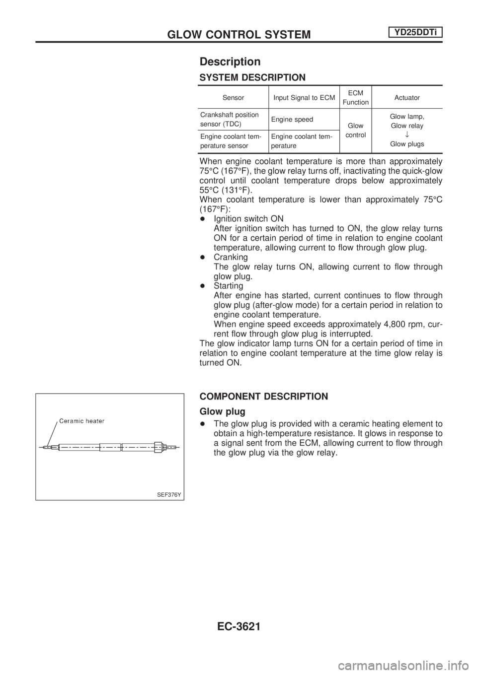
COMPONENT DESCRIPTION
Glow plug
+The glow plug is provided with a ceramic heating element to
obtain a high-temperature resistance. It glows in response to
a signal sent from the ECM, allowing current to flow through
the glow plug via the glow relay.
SEF376Y
GLOW CONTROL SYSTEMYD25DDTi
EC-3621
Page 675 of 1306
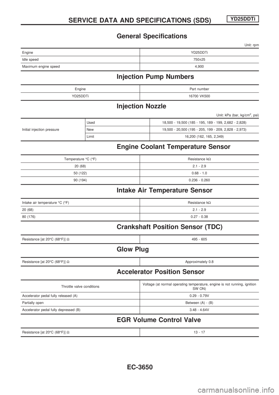
General Specifications
Unit: rpm
EngineYD25DDTi
Idle speed750 25
Maximum engine speed4,900
Injection Pump Numbers
Engine Part number
YD25DDTi 16700 VK500
Injection Nozzle
Unit: kPa (bar, kg/cm2, psi)
Initial injection pressureUsed 18,500 - 19,500 (185 - 195, 189 - 199, 2,682 - 2,828)
New 19,500 - 20,500 (195 - 205, 199 - 209, 2,828 - 2,973)
Limit 16,200 (162, 165, 2,349)
Engine Coolant Temperature Sensor
Temperature ÉC (ÉF) Resistance kW
20 (68) 2.1 - 2.9
50 (122) 0.68 - 1.0
90 (194) 0.236 - 0.260
Intake Air Temperature Sensor
Intake air temperature ÉC (ÉF)Resistance kW
20 (68)2.1 - 2.9
80 (176)0.27 - 0.38
Crankshaft Position Sensor (TDC)
Resistance [at 20ÉC (68ÉF)]W495 - 605
Glow Plug
Resistance [at 20ÉC (68ÉF)]WApproximately 0.8
Accelerator Position Sensor
Throttle valve conditionsVoltage (at normal operating temperature, engine is not running, ignition
SW ON)
Accelerator pedal fully released (A) 0.29 - 0.79V
Partially openBetween (A) - (B)
Accelerator pedal fully depressed (B) 3.48 - 4.64V
EGR Volume Control Valve
Resistance [at 20ÉC (68ÉF)]W13-17
SERVICE DATA AND SPECIFICATIONS (SDS)YD25DDTi
EC-3650
Page 679 of 1306
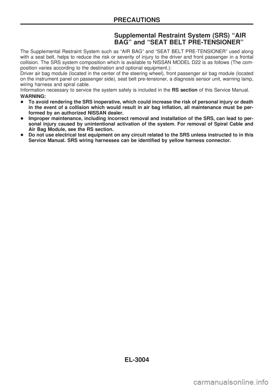
Supplemental Restraint System (SRS) ªAIR
BAGº and ªSEAT BELT PRE-TENSIONERº
The Supplemental Restraint System such as ªAIR BAGº and ªSEAT BELT PRE-TENSIONERº used along
with a seat belt, helps to reduce the risk or severity of injury to the driver and front passenger in a frontal
collision. The SRS system composition which is available to NISSAN MODEL D22 is as follows (The com-
position varies according to the destination and optional equipment.):
Driver air bag module (located in the center of the steering wheel), front passenger air bag module (located
on the instrument panel on passenger side), seat belt pre-tensioner, a diagnosis sensor unit, warning lamp,
wiring harness and spiral cable.
Information necessary to service the system safely is included in theRS sectionof this Service Manual.
WARNING:
+To avoid rendering the SRS inoperative, which could increase the risk of personal injury or death
in the event of a collision which would result in air bag inflation, all maintenance must be per-
formed by an authorized NISSAN dealer.
+Improper maintenance, including incorrect removal and installation of the SRS, can lead to per-
sonal injury caused by unintentional activation of the system. For removal of Spiral Cable and
Air Bag Module, see the RS section.
+Do not use electrical test equipment on any circuit related to the SRS unless instructed to in this
Service Manual. SRS wiring harnesses can be identified by yellow harness connector.
PRECAUTIONS
EL-3004