2001 NISSAN PICK-UP sensor
[x] Cancel search: sensorPage 1073 of 1306
Supplemental Restraint System (SRS) ªAIR
BAGº and ªSEAT BELT PRE-TENSIONERº
The Supplemental Restraint System such as ªAIR BAGº and ªSEAT BELT PRE-TENSIONERº used along
with a seat belt, helps to reduce the risk or severity of injury to the driver and front passenger in a frontal
collision. The SRS composition which is available to NISSAN MODEL D22 is as follows (The composition
varies according to the destination and optional equipment.):
Driver air bag module (located in the center of the steering wheel), front passenger air bag module (located
on the instrument panel on passenger side), seat belt pre-tensioner, a diagnosis sensor unit, warning lamp,
wiring harness and spiral cable.
WARNING:
+To avoid rendering the SRS inoperative, which could increase the risk of personal injury or death
in the event of a collision which would result in air bag inflation, all maintenance must be per-
formed by an authorized NISSAN dealer.
+Improper maintenance, including incorrect removal and installation of the SRS, can lead to per-
sonal injury caused by unintentional activation of the system.
+Do not use electrical test equipment on any circuit related to the SRS unless instructed to in this
Service Manual. SRS wiring harnesses can be identified by yellow harness connector.
PRECAUTION
RS-3002
Page 1074 of 1306
Precautions for SRS ªAIR BAGº and ªSEAT
BELT PRE-TENSIONERº Service
+Do not use electrical test equipment to check SRS circuits unless instructed to in this Service Manual.
+Before servicing the SRS, turn ignition switch ªOFFº, disconnect battery ground cable and wait at least 3
minutes.
For approximately 3 minutes after the cables are removed, it is still possible for the air bag and seat belt
pre-tensioner to deploy. Therefore, do not work on any SRS connectors or wires until at least 3 minutes have
passed.
+Diagnosis sensor unit must always be installed with their arrow marks ª
Sº pointing towards the front of
the vehicle for proper operation. Also check diagnosis sensor unit for cracks, deformities or rust before
installation and replace as required.
+The spiral cable must be aligned with the neutral position since its rotations are limited. Do not attempt
to turn steering wheel or column after removal of steering gear.
+Handle air bag module carefully. Always place driver and passenger air bag modules with the pad side
facing upward.
+Conduct self-diagnosis to check entire SRS for proper function after replacing any components.
+After air bag inflates, the front instrument panel assembly should be replaced if damaged.
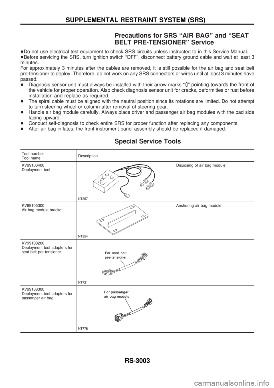
Special Service Tools
Tool number
Tool nameDescription
KV99106400
Deployment tool
NT357
Disposing of air bag module
KV99105300
Air bag module bracket
NT354
Anchoring air bag module
KV99108200
Deployment tool adapters for
seat belt pre-tensioner
NT721
KV99108300
Deployment tool adapters for
passenger air bag
NT776
SUPPLEMENTAL RESTRAINT SYSTEM (SRS)
RS-3003
Page 1076 of 1306
Removal and Installation Ð Diagnosis
Sensor Unit
CAUTION:
+Before servicing SRS, turn the ignition switch off, disconnect battery ground cable and wait at
least 3 minutes.
+Do not use old bolts and nuts after removal; replace with new ones.
+Check diagnosis sensor unit for proper installation.
+Check diagnosis sensor unit to ensure it is free of deformities, dents, cracks or rust. If it shows
any visible signs of damage, replace it with a new one.
+Check diagnosis sensor unit brackets to ensure they are free of deformities and rust.
+After replacement of diagnosis sensor unit, check SRS function and perform self-diagnosis for
SRS. Refer to ªSelf-diagnosisº for details. (RS-3020)
+Do not attempt to disassemble diagnosis sensor unit.
+Replace diagnosis sensor unit if it has been dropped or sustained an impact.
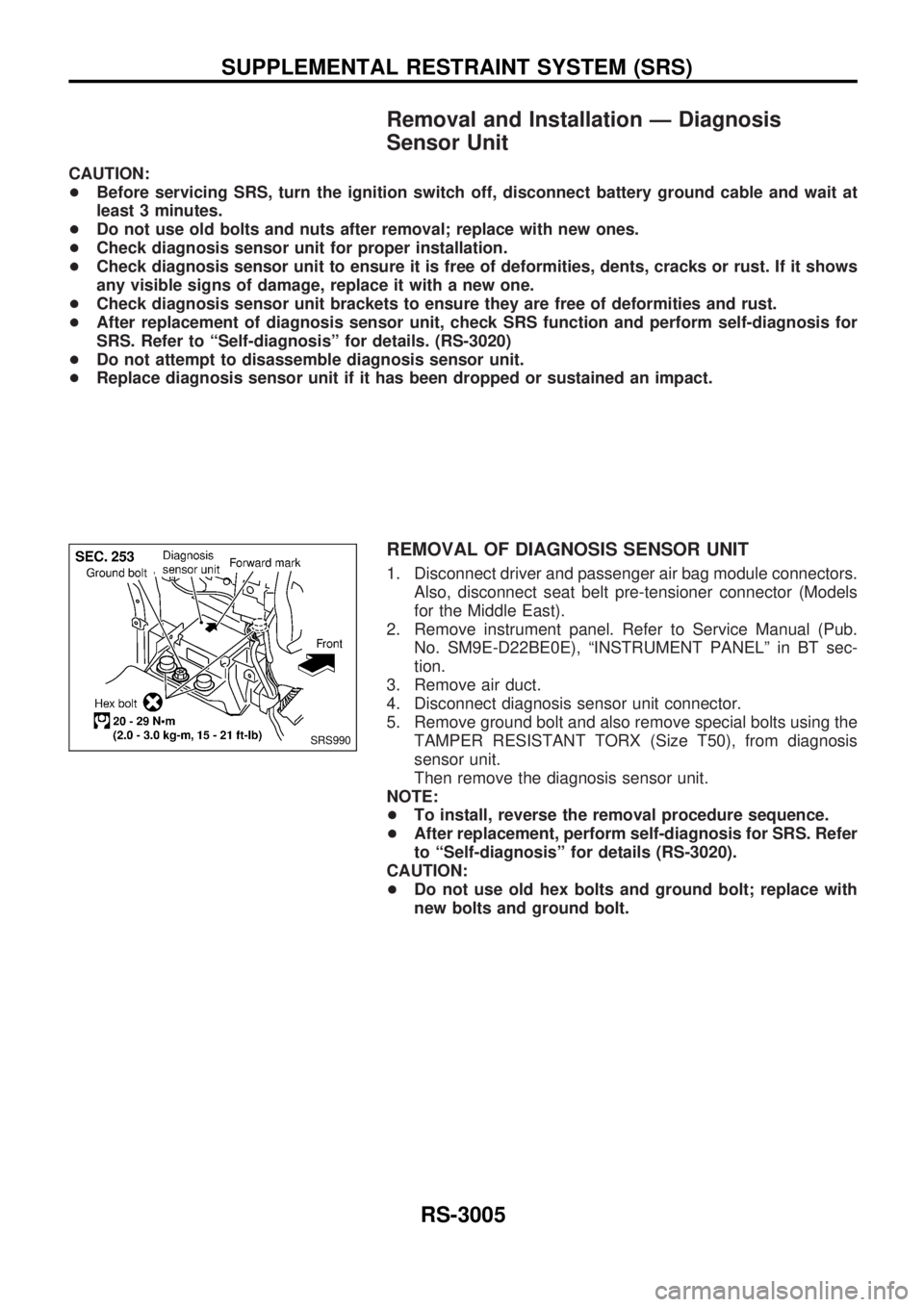
REMOVAL OF DIAGNOSIS SENSOR UNIT
1. Disconnect driver and passenger air bag module connectors.
Also, disconnect seat belt pre-tensioner connector (Models
for the Middle East).
2. Remove instrument panel. Refer to Service Manual (Pub.
No. SM9E-D22BE0E), ªINSTRUMENT PANELº in BT sec-
tion.
3. Remove air duct.
4. Disconnect diagnosis sensor unit connector.
5. Remove ground bolt and also remove special bolts using the
TAMPER RESISTANT TORX (Size T50), from diagnosis
sensor unit.
Then remove the diagnosis sensor unit.
NOTE:
+To install, reverse the removal procedure sequence.
+After replacement, perform self-diagnosis for SRS. Refer
to ªSelf-diagnosisº for details (RS-3020).
CAUTION:
+Do not use old hex bolts and ground bolt; replace with
new bolts and ground bolt.
SRS990
SUPPLEMENTAL RESTRAINT SYSTEM (SRS)
RS-3005
Page 1085 of 1306
Trouble Diagnoses Introduction
CAUTION:
+Do not use electrical test equipment on any circuit related to the SRS unless instructed to in this
Service Manual. SRS wiring harnesses can be identified with yellow harness connector.
+Do not attempt to repair, splice or modify the SRS wiring harness. If the harness is damaged,
replace it with a new one.
+Keep ground portion clean.
DIAGNOSIS FUNCTION
The SRS self-diagnosis results can be read by using ªAIR BAGº warning lamp, and/or CONSULT-II. The
reading of these results is accomplished using one of two modes Ð ªUser modeº and ªDiagnosis modeº.
The User mode is exclusively prepared for the customer (driver). This mode warns the driver of a system
malfunction through the operation of the ªAIR BAGº warning lamp.
The Diagnosis mode allows the technician to locate and inspect the malfunctioning part.
The mode applications for the ªAIR BAGº warning lamp and CONSULT-II are as follows:
User mode Diagnosis mode Display type
ªAIR BAGº warning lamp X X ON-OFF operation
CONSULT-II Ð X Monitoring
NOTE:
Seat belt pre-tensioner malfunction is indicated by ªAIR BAGº warning lamp.
DIAGNOSIS MODE FOR CONSULT-II
+ªSELF-DIAG [CURRENT]º
A current Self-diagnosis result (also indicated by the warning lamp flashes in the Diagnosis mode) is
displayed on the CONSULT-II screen in real time. This refers to a malfunctioning part requiring repairs.
+ªSELF-DIAG [PAST]º
Diagnosis results previously stored in the memory are displayed on the CONSULT-II screen. The stored
results are not erased until memory erasing is executed.
+ªTROUBLE DIAG RECORDº
With TROUBLE DIAG RECORD, diagnosis results previously erased by a reset operation can be dis-
played on the CONSULT-II screen.
+ªECU DISCRIMINATED NO.º
The diagnosis sensor unit for each vehicle model is assigned with its own, individual classification num-
ber. This number will be displayed on the CONSULT-II screen, as shown at left. When replacing the
diagnosis sensor unit, refer to the part number for the compatibility. After installation, replacement with
a correct unit can be checked by confirming this classification number on the CONSULT-II screen.
For NISSAN MODEL D22, the diagnosis sensor unit classification number assigned are as follows:
MODEL ECU DISCRIMINATED NO.
Single air bag5A37
Single air bag and seat belt pre-tensioner 5A39
Dual air bags5A38
Dual air bags and seat belt pre-tensioner 5A3A
TROUBLE DIAGNOSES Ð Supplemental Restraint System (SRS)
RS-3014
Page 1091 of 1306
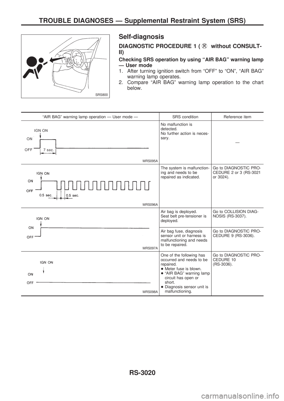
Self-diagnosis
DIAGNOSTIC PROCEDURE 1 (without CONSULT-
II)
Checking SRS operation by using ªAIR BAGº warning lamp
Ð User mode
1. After turning ignition switch from ªOFFº to ªONº, ªAIR BAGº
warning lamp operates.
2. Compare ªAIR BAGº warning lamp operation to the chart
below.
ªAIR BAGº warning lamp operation Ð User mode Ð SRS condition Reference item
MRS095A
No malfunction is
detected.
No further action is neces-
sary.
Ð
MRS096A
The system is malfunction-
ing and needs to be
repaired as indicated.Go to DIAGNOSTIC PRO-
CEDURE 2 or 3 (RS-3021
or 3024).
MRS097A
Air bag is deployed.
Seat belt pre-tensioner is
deployed.Go to COLLISION DIAG-
NOSIS (RS-3037).
Air bag fuse, diagnosis
sensor unit or harness is
malfunctioning and needs
to be repaired.Go to DIAGNOSTIC PRO-
CEDURE 9 (RS-3036).
MRS098A
One of the following has
occurred and needs to be
repaired.
+Meter fuse is blown.
+ªAIR BAGº warning lamp
circuit has open or
short.
+Diagnosis sensor unit is
malfunctioning.Go to DIAGNOSTIC PRO-
CEDURE 10
(RS-3036).
SRS800
TROUBLE DIAGNOSES Ð Supplemental Restraint System (SRS)
RS-3020
Page 1094 of 1306
![NISSAN PICK-UP 2001 Repair Manual CONSULT-II DIAGNOSTIC CODE CHART (ªSELF-DIAG [CURRENT]º)
Diagnostic item ExplanationRepair order
Recheck SRS at each
replacement.
NO DTC IS DETECTED When malfunction is indicated
by the ªAIR BAGº NISSAN PICK-UP 2001 Repair Manual CONSULT-II DIAGNOSTIC CODE CHART (ªSELF-DIAG [CURRENT]º)
Diagnostic item ExplanationRepair order
Recheck SRS at each
replacement.
NO DTC IS DETECTED When malfunction is indicated
by the ªAIR BAGº](/manual-img/5/57372/w960_57372-1093.png)
CONSULT-II DIAGNOSTIC CODE CHART (ªSELF-DIAG [CURRENT]º)
Diagnostic item ExplanationRepair order
Recheck SRS at each
replacement.
NO DTC IS DETECTED When malfunction is indicated
by the ªAIR BAGº warning lamp
in User mode+Low battery voltage (Less
than 9V)+Go to DIAGNOSTIC PROCE-
DURE 4 (RS-3028) after
charging battery.
+Self-diagnostic result ªSELF-
DIAG [PAST]º (previously
stored in the memory) might
not be erased after repair.
+Intemittent malfunction has
been detected in the past.+Go to DIAGNOSTIC PROCE-
DURE 6 (RS-3032).
+No malfunction is detected.+Go to DIAGNOSTIC PROCE-
DURE 4 (RS-3028).
DRIVER AIRBAG MOD-
ULE
[OPEN]+Driver air bag module circuit is open. (including the spiral cable) 1. Visually check the wiring har-
ness connection.
2. Replace the harness if it has
visible damage.
3. Replace the spiral cable.
4. Replace driver air bag mod-
ule.
(Before disposal, it must be
deployed.)
5. Replace the diagnosis sensor
unit.
6. Replace the related harness. DRIVER AIRBAG MOD-
ULE
[VB-SHORT]+Driver air bag module circuit is shorted to a power supply circuit.
(including the spiral cable)
DRIVER AIRBAG MOD-
ULE
[GND-SHORT]+Driver air bag module circuit is shorted to ground. (including the
spiral cable)
DRIVER AIRBAG MOD-
ULE
[SHORT]+Driver air bag module circuits are shorted to each other.
ASSIST A/B MODULE
[VB-SHORT]+Front passenger air bag module circuit is shorted to a power sup-
ply circuit.1. Visually check the wiring har-
ness connection.
2. Replace the harness if it has
visible damage.
3. Replace front passenger air
bag module.
(Before disposal, it must be
deployed.)
4. Replace the diagnosis sensor
unit.
5. Replace the related harness. ASSIST A/B MODULE
[OPEN]+Front passenger air bag module circuit is open.
ASSIST A/B MODULE
[GND-SHORT]+Front passenger air bag module circuit is shorted to ground.
ASSIST A/B MODULE
[SHORT]+Front passenger air bag module circuits are shorted to each
other.
PRE-TEN FRONT LH
[OPEN]+The circuit for seat belt pre-tensioner (LH) is open. 1. Visually check the wiring har-
ness connections.
2. Replace the harness if it has
visible damage.
3. Replace seat belt (LH).
(Before disposing, it must be
deactivated.)
4. Replace the diagnosis sensor
unit.
5. Replace the related harness. PRE-TEN FRONT LH
[VB-SHORT]+The circuit for seat belt pre-tensioner (LH) is shorted to a power
supply circuit.
PRE-TEN FRONT LH
[GND-SHORT]+The circuit for seat belt pre-tensioner (LH) is shorted to ground.
PRE-TEN FRONT RH
[OPEN/VB-SHORT]+The circuit for seat belt pre-tensioner (RH) is open or shorted to
some power supply circuit.1. Visually check the wiring har-
ness connections.
2. Replace the harness if it has
visible damage.
3. Replace seat belt (RH).
(Before disposing, it must be
deactivated.)
4. Replace the diagnosis sensor
unit.
5. Replace the related harness. PRE-TEN FRONT RH
[VB-SHORT]+The circuit for seat belt pre-tensioner (RH) is shorted to a power
supply circuit.
PRE-TEN FRONT RH
[GND-SHORT]+The circuit for front RH pre-tensioner is shorted to ground.
* Follow the procedures in numerical order when repairing malfunctioning parts. Confirm whether malfunction is eliminated
using the air bag warning lamp or CONSULT-II each time repair is finished. If malfunction is still observed, proceed to the
next step. When malfunction is eliminated, further repair work is not required.
TROUBLE DIAGNOSES Ð Supplemental Restraint System (SRS)
Self-diagnosis (Cont'd)
RS-3023
Page 1095 of 1306
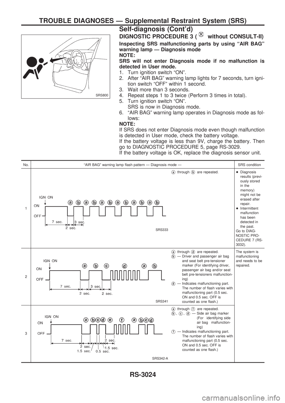
DIGNOSTIC PROCEDURE 3 (without CONSULT-II)
Inspecting SRS malfunctioning parts by using ªAIR BAGº
warning lamp Ð Diagnosis mode
NOTE:
SRS will not enter Diagnosis mode if no malfunction is
detected in User mode.
1. Turn ignition switch ªONº.
2. After ªAIR BAGº warning lamp lights for 7 seconds, turn igni-
tion switch ªOFFº within 1 second.
3. Wait more than 3 seconds.
4. Repeat steps 1 to 3 twice (Perform 3 times in total).
5. Turn ignition switch ªONº.
SRS is now in Diagnosis mode.
6. ªAIR BAGº warning lamp operates in Diagnosis mode as fol-
lows:
NOTE:
If SRS does not enter Diagnosis mode even though malfunction
is detected in User mode, check the battery voltage.
If the battery voltage is less than 9V, charge the battery. Then
go to DIAGNOSTIC PROCEDURE 5, page RS-3029.
If the battery voltage is OK, replace the diagnosis sensor unit.
No. ªAIR BAGº warning lamp flash pattern Ð Diagnosis mode Ð SRS condition
1
SRS333
VathroughVbare repeated.+Diagnosis
results (previ-
ously stored
in the
memory)
might not be
erased after
repair.
+Intermittent
malfunction
has been
detected in
the past.
Go to DIAG-
NOSTIC PRO-
CEDURE 7 (RS-
3032).
2
SRS341
VathroughVdare repeated.
VbÐ Driver and passenger air bag
and seat belt pre-tensioner
marker (For identifying driver,
passenger air bag and/or seat
belt pre-tensioners malfunction-
ing)
VdÐ Indicates malfunctioning part.
The number of flash varies with
malfunctioning part (0.5 sec.
ON and 0.5 sec. OFF is
counted as one flash.)The system is
malfunctioning
and needs to be
repaired.
3
SRS342-A
VathroughVfare repeated.
Vb,Vc,VdÐ Side air bag marker
(For identifying side
air bag malfunction-
ing)
VfÐ Indicates malfunctioning part.
The number of flash varies with
malfunctioning part (0.5 sec.
ON and 0.5 sec. OFF is
counted as one flash.)
SRS800
TROUBLE DIAGNOSES Ð Supplemental Restraint System (SRS)
Self-diagnosis (Cont'd)
RS-3024
Page 1096 of 1306
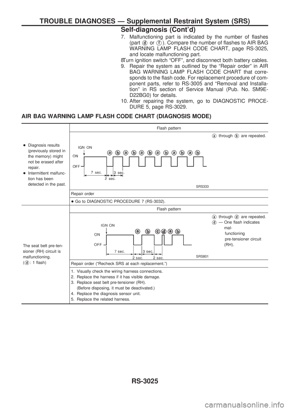
7. Malfunctioning part is indicated by the number of flashes
(part
VdorVf). Compare the number of flashes to AIR BAG
WARNING LAMP FLASH CODE CHART, page RS-3025,
and locate malfunctioning part.
8.Turn ignition switch ªOFFº, and disconnect both battery cables.
9. Repair the system as outlined by the ªRepair orderº in AIR
BAG WARNING LAMP FLASH CODE CHART that corre-
sponds to the flash code. For replacement procedure of com-
ponent parts, refer to RS-3005 and ªRemoval and Installa-
tionº in RS section of Service Manual (Pub. No. SM9E-
D22BG0) for details.
10. After repairing the system, go to DIAGNOSTIC PROCE-
DURE 5, page RS-3029.
AIR BAG WARNING LAMP FLASH CODE CHART (DIAGNOSIS MODE)
+Diagnosis results
(previously stored in
the memory) might
not be erased after
repair.
+Intermittent malfunc-
tion has been
detected in the past.Flash pattern
SRS333
VathroughVbare repeated.
Repair order
+Go to DIAGNOSTIC PROCEDURE 7 (RS-3032).
The seat belt pre-ten-
sioner (RH) circuit is
malfunctioning.
(
Vd: 1 flash)Flash pattern
SRS801
VathroughVdare repeated.
VdÐ One flash indicates
mal-
functioning
pre-tensioner circuit
(RH).
Repair order (ªRecheck SRS at each replacement.º)
1. Visually check the wiring harness connections.
2. Replace the harness if it has visible damage.
3. Replace seat belt pre-tensioner (RH).
(Before disposing, it must be deactivated.)
4. Replace the diagnosis sensor unit.
5. Replace the related harness.
TROUBLE DIAGNOSES Ð Supplemental Restraint System (SRS)
Self-diagnosis (Cont'd)
RS-3025