2001 NISSAN PICK-UP sensor
[x] Cancel search: sensorPage 1097 of 1306
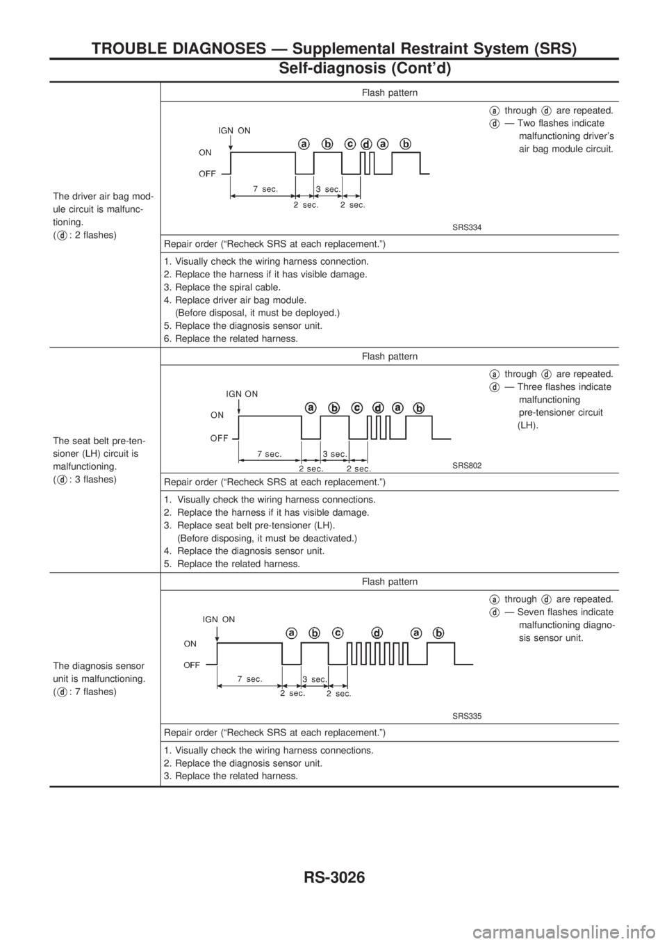
The driver air bag mod-
ule circuit is malfunc-
tioning.
(
Vd: 2 flashes)Flash patternSRS334
VathroughVdare repeated.
VdÐ Two flashes indicate
malfunctioning driver's
air bag module circuit.
Repair order (ªRecheck SRS at each replacement.º)
1. Visually check the wiring harness connection.
2. Replace the harness if it has visible damage.
3. Replace the spiral cable.
4. Replace driver air bag module.
(Before disposal, it must be deployed.)
5. Replace the diagnosis sensor unit.
6. Replace the related harness.
The seat belt pre-ten-
sioner (LH) circuit is
malfunctioning.
(
Vd: 3 flashes)Flash pattern
SRS802
VathroughVdare repeated.
VdÐ Three flashes indicate
malfunctioning
pre-tensioner circuit
(LH).
Repair order (ªRecheck SRS at each replacement.º)
1. Visually check the wiring harness connections.
2. Replace the harness if it has visible damage.
3. Replace seat belt pre-tensioner (LH).
(Before disposing, it must be deactivated.)
4. Replace the diagnosis sensor unit.
5. Replace the related harness.
The diagnosis sensor
unit is malfunctioning.
(
Vd: 7 flashes)Flash pattern
SRS335
VathroughVdare repeated.
VdÐ Seven flashes indicate
malfunctioning diagno-
sis sensor unit.
Repair order (ªRecheck SRS at each replacement.º)
1. Visually check the wiring harness connections.
2. Replace the diagnosis sensor unit.
3. Replace the related harness.
TROUBLE DIAGNOSES Ð Supplemental Restraint System (SRS)
Self-diagnosis (Cont'd)
RS-3026
Page 1098 of 1306
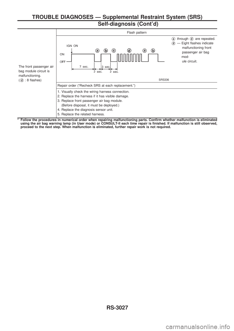
The front passenger air
bag module circuit is
malfunctioning.
(
Vd: 8 flashes)Flash patternSRS336
VathroughVdare repeated.
VdÐ Eight flashes indicate
malfunctioning front
passenger air bag
mod-
ule circuit.
Repair order (ªRecheck SRS at each replacement.º)
1. Visually check the wiring harness connection.
2. Replace the harness if it has visible damage.
3. Replace front passenger air bag module.
(Before disposal, it must be deployed.)
4. Replace the diagnosis sensor unit.
5. Replace the related harness.
* Follow the procedures in numerical order when repairing malfunctioning parts. Confirm whether malfunction is eliminated
using the air bag warning lamp (in User mode) or CONSULT-II each time repair is finished. If malfunction is still observed,
proceed to the next step. When malfunction is eliminated, further repair work is not required.
TROUBLE DIAGNOSES Ð Supplemental Restraint System (SRS)
Self-diagnosis (Cont'd)
RS-3027
Page 1101 of 1306
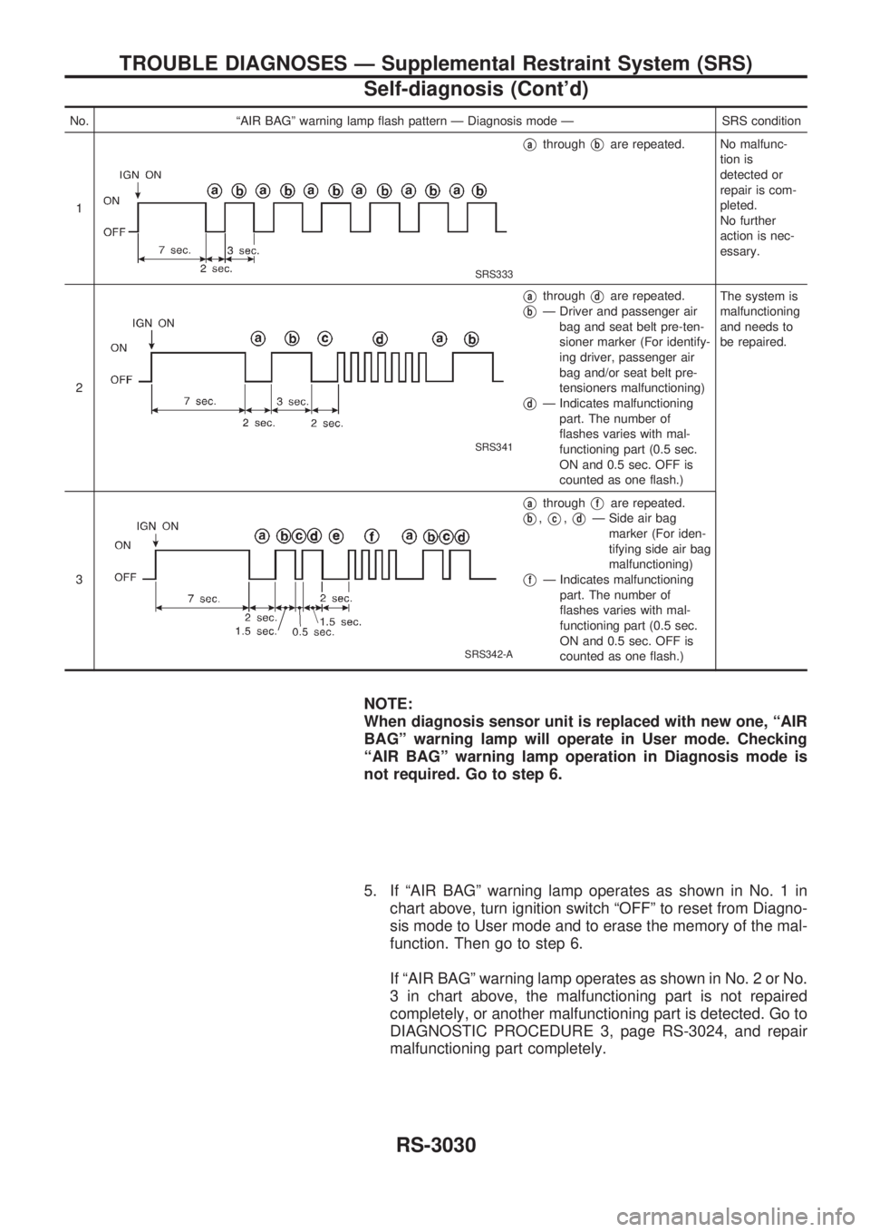
No. ªAIR BAGº warning lamp flash pattern Ð Diagnosis mode Ð SRS condition
1
SRS333
VathroughVbare repeated. No malfunc-
tion is
detected or
repair is com-
pleted.
No further
action is nec-
essary.
2
SRS341
VathroughVdare repeated.
VbÐ Driver and passenger air
bag and seat belt pre-ten-
sioner marker (For identify-
ing driver, passenger air
bag and/or seat belt pre-
tensioners malfunctioning)
VdÐ Indicates malfunctioning
part. The number of
flashes varies with mal-
functioning part (0.5 sec.
ON and 0.5 sec. OFF is
counted as one flash.)The system is
malfunctioning
and needs to
be repaired.
3
SRS342-A
VathroughVfare repeated.
Vb,Vc,VdÐ Side air bag
marker (For iden-
tifying side air bag
malfunctioning)
VfÐ Indicates malfunctioning
part. The number of
flashes varies with mal-
functioning part (0.5 sec.
ON and 0.5 sec. OFF is
counted as one flash.)
NOTE:
When diagnosis sensor unit is replaced with new one, ªAIR
BAGº warning lamp will operate in User mode. Checking
ªAIR BAGº warning lamp operation in Diagnosis mode is
not required. Go to step 6.
5. If ªAIR BAGº warning lamp operates as shown in No. 1 in
chart above, turn ignition switch ªOFFº to reset from Diagno-
sis mode to User mode and to erase the memory of the mal-
function. Then go to step 6.
If ªAIR BAGº warning lamp operates as shown in No. 2 or No.
3 in chart above, the malfunctioning part is not repaired
completely, or another malfunctioning part is detected. Go to
DIAGNOSTIC PROCEDURE 3, page RS-3024, and repair
malfunctioning part completely.
TROUBLE DIAGNOSES Ð Supplemental Restraint System (SRS)
Self-diagnosis (Cont'd)
RS-3030
Page 1102 of 1306
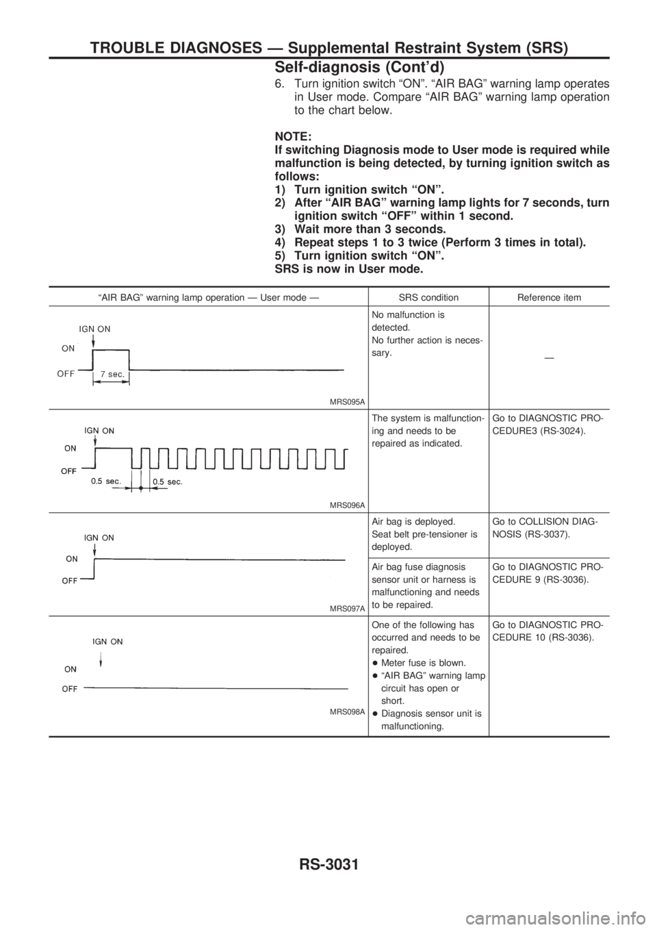
6. Turn ignition switch ªONº. ªAIR BAGº warning lamp operates
in User mode. Compare ªAIR BAGº warning lamp operation
to the chart below.
NOTE:
If switching Diagnosis mode to User mode is required while
malfunction is being detected, by turning ignition switch as
follows:
1) Turn ignition switch ªONº.
2) After ªAIR BAGº warning lamp lights for 7 seconds, turn
ignition switch ªOFFº within 1 second.
3) Wait more than 3 seconds.
4) Repeat steps 1 to 3 twice (Perform 3 times in total).
5) Turn ignition switch ªONº.
SRS is now in User mode.
ªAIR BAGº warning lamp operation Ð User mode Ð SRS condition Reference item
MRS095A
No malfunction is
detected.
No further action is neces-
sary.
Ð
MRS096A
The system is malfunction-
ing and needs to be
repaired as indicated.Go to DIAGNOSTIC PRO-
CEDURE3 (RS-3024).
MRS097A
Air bag is deployed.
Seat belt pre-tensioner is
deployed.Go to COLLISION DIAG-
NOSIS (RS-3037).
Air bag fuse diagnosis
sensor unit or harness is
malfunctioning and needs
to be repaired.Go to DIAGNOSTIC PRO-
CEDURE 9 (RS-3036).
MRS098A
One of the following has
occurred and needs to be
repaired.
+Meter fuse is blown.
+ªAIR BAGº warning lamp
circuit has open or
short.
+Diagnosis sensor unit is
malfunctioning.Go to DIAGNOSTIC PRO-
CEDURE 10 (RS-3036).
TROUBLE DIAGNOSES Ð Supplemental Restraint System (SRS)
Self-diagnosis (Cont'd)
RS-3031
Page 1105 of 1306
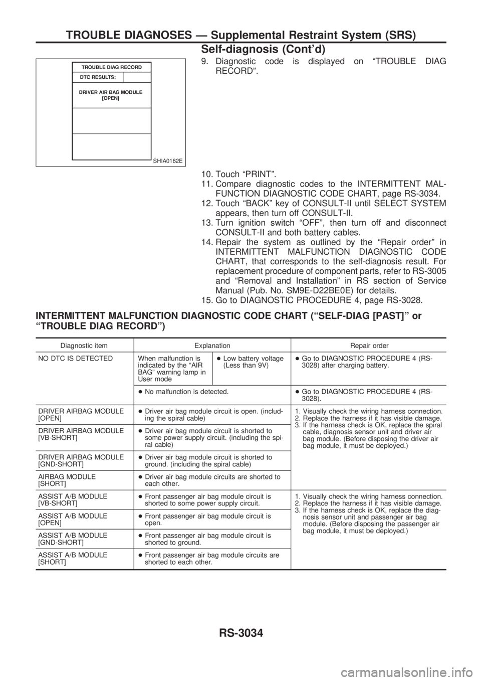
9. Diagnostic code is displayed on ªTROUBLE DIAG
RECORDº.
10. Touch ªPRINTº.
11. Compare diagnostic codes to the INTERMITTENT MAL-
FUNCTION DIAGNOSTIC CODE CHART, page RS-3034.
12. Touch ªBACKº key of CONSULT-II until SELECT SYSTEM
appears, then turn off CONSULT-II.
13. Turn ignition switch ªOFFº, then turn off and disconnect
CONSULT-II and both battery cables.
14. Repair the system as outlined by the ªRepair orderº in
INTERMITTENT MALFUNCTION DIAGNOSTIC CODE
CHART, that corresponds to the self-diagnosis result. For
replacement procedure of component parts, refer to RS-3005
and ªRemoval and Installationº in RS section of Service
Manual (Pub. No. SM9E-D22BE0E) for details.
15. Go to DIAGNOSTIC PROCEDURE 4, page RS-3028.
INTERMITTENT MALFUNCTION DIAGNOSTIC CODE CHART (ªSELF-DIAG [PAST]º or
ªTROUBLE DIAG RECORDº)
Diagnostic item Explanation Repair order
NO DTC IS DETECTED When malfunction is
indicated by the ªAIR
BAGº warning lamp in
User mode+Low battery voltage
(Less than 9V)+Go to DIAGNOSTIC PROCEDURE 4 (RS-
3028) after charging battery.
+No malfunction is detected.+Go to DIAGNOSTIC PROCEDURE 4 (RS-
3028).
DRIVER AIRBAG MODULE
[OPEN]+Driver air bag module circuit is open. (includ-
ing the spiral cable)1. Visually check the wiring harness connection.
2. Replace the harness if it has visible damage.
3. If the harness check is OK, replace the spiral
cable, diagnosis sensor unit and driver air
bag module. (Before disposing the driver air
bag module, it must be deployed.) DRIVER AIRBAG MODULE
[VB-SHORT]+Driver air bag module circuit is shorted to
some power supply circuit. (including the spi-
ral cable)
DRIVER AIRBAG MODULE
[GND-SHORT]+Driver air bag module circuit is shorted to
ground. (including the spiral cable)
AIRBAG MODULE
[SHORT]+Driver air bag module circuits are shorted to
each other.
ASSIST A/B MODULE
[VB-SHORT]+Front passenger air bag module circuit is
shorted to some power supply circuit.1. Visually check the wiring harness connection.
2. Replace the harness if it has visible damage.
3. If the harness check is OK, replace the diag-
nosis sensor unit and passenger air bag
module. (Before disposing the passenger air
bag module, it must be deployed.) ASSIST A/B MODULE
[OPEN]+Front passenger air bag module circuit is
open.
ASSIST A/B MODULE
[GND-SHORT]+Front passenger air bag module circuit is
shorted to ground.
ASSIST A/B MODULE
[SHORT]+Front passenger air bag module circuits are
shorted to each other.
SHIA0182E
TROUBLE DIAGNOSES Ð Supplemental Restraint System (SRS)
Self-diagnosis (Cont'd)
RS-3034
Page 1106 of 1306
![NISSAN PICK-UP 2001 Repair Manual Diagnostic item Explanation Repair order
PRE-TEN FRONT LH
[OPEN]+The circuit for seat belt pre-tensioner (LH) is
open or shorted to a power supply circuit.1. Visually check the wiring harness connec-
NISSAN PICK-UP 2001 Repair Manual Diagnostic item Explanation Repair order
PRE-TEN FRONT LH
[OPEN]+The circuit for seat belt pre-tensioner (LH) is
open or shorted to a power supply circuit.1. Visually check the wiring harness connec-](/manual-img/5/57372/w960_57372-1105.png)
Diagnostic item Explanation Repair order
PRE-TEN FRONT LH
[OPEN]+The circuit for seat belt pre-tensioner (LH) is
open or shorted to a power supply circuit.1. Visually check the wiring harness connec-
tions.
2. Replace the harness if it has visible damage.
3. If the harness check is OK, replace the diag-
nosis sensor unit and seat belt (LH).
(Before disposing the seat belt (LH) pre-
tensioner, it must be deployed.) PRE-TEN FRONT LH
[VB-SHORT]+The circuit for seat belt pre-tensioner (LH) is
shorted to a power supply circuit.
PRE-TEN FRONT LH
[GND-SHORT]+The circuit for seat belt pre-tensioner (LH) is
shorted to ground.
PRE-TEN FRONT RH
[OPEN/VB-SHORT]+The circuit for seat belt pre-tensioner (RH) is
open or shorted to a power supply circuit.1. Visually check the wiring harness connec-
tions.
2. Replace the harness if it has visible damage.
3. If the harness check is OK, replace the diag-
nosis sensor unit and seat belt (RH).
(Before disposing the seat belt (RH) pre-
tensioner, it must be deployed.) PRE-TEN FRONT RH
[VB-SHORT]+The circuit for seat belt pre-tensioner (RH) is
shorted to a power supply circuit.
PRE-TEN FRONT RH
[GND-SHORT]+The circuit for seat belt pre-tensioner (RH) is
shorted to ground.
CONTROL UNIT+Diagnosis sensor unit is malfunctioning. 1. Visually check the wiring harness connection.
2. Replace the harness if it has visible damage.
3. If the harness check is OK, replace the diag-
nosis sensor unit.
* Follow the procedures in numerical order when repairing malfunctioning parts, then make the final system check.
TROUBLE DIAGNOSES Ð Supplemental Restraint System (SRS)
Self-diagnosis (Cont'd)
RS-3035
Page 1107 of 1306
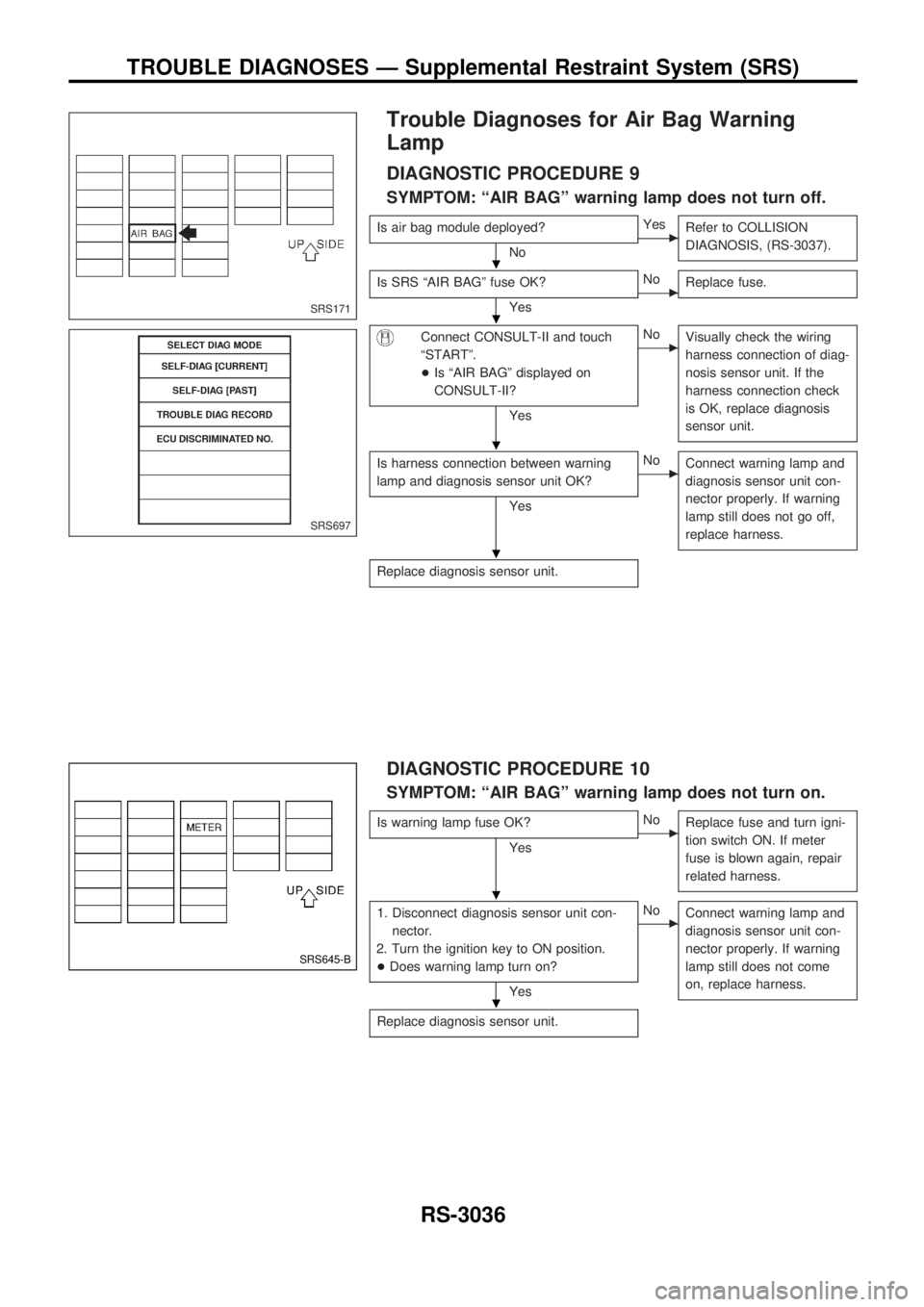
Trouble Diagnoses for Air Bag Warning
Lamp
DIAGNOSTIC PROCEDURE 9
SYMPTOM: ªAIR BAGº warning lamp does not turn off.
Is air bag module deployed?
NocYes
Refer to COLLISION
DIAGNOSIS, (RS-3037).
Is SRS ªAIR BAGº fuse OK?
YescNo
Replace fuse.
Connect CONSULT-II and touch
ªSTARTº.
+Is ªAIR BAGº displayed on
CONSULT-II?
Yes
cNo
Visually check the wiring
harness connection of diag-
nosis sensor unit. If the
harness connection check
is OK, replace diagnosis
sensor unit.
Is harness connection between warning
lamp and diagnosis sensor unit OK?
Yes
cNo
Connect warning lamp and
diagnosis sensor unit con-
nector properly. If warning
lamp still does not go off,
replace harness.
Replace diagnosis sensor unit.
DIAGNOSTIC PROCEDURE 10
SYMPTOM: ªAIR BAGº warning lamp does not turn on.
Is warning lamp fuse OK?
YescNo
Replace fuse and turn igni-
tion switch ON. If meter
fuse is blown again, repair
related harness.
1. Disconnect diagnosis sensor unit con-
nector.
2. Turn the ignition key to ON position.
+Does warning lamp turn on?
Yes
cNo
Connect warning lamp and
diagnosis sensor unit con-
nector properly. If warning
lamp still does not come
on, replace harness.
Replace diagnosis sensor unit.
SRS171
SRS697
SRS645-B
.
.
.
.
.
.
TROUBLE DIAGNOSES Ð Supplemental Restraint System (SRS)
RS-3036
Page 1108 of 1306
FOR FRONTAL COLLISION
To repair the SRS for a frontal collision, perform the following steps.
When SRS (except the side air bag) is activated in a collision:
V1Replace the diagnosis sensor unit.
V2Remove the air bag modules (except the side air bag module).
V3Check the SRS components using the table shown below:
+Replace any SRS components showing visible signs of damage (dents, cracks, deformation).
V4Install new air bag modules (except the side air bag module).
V5Conduct self-diagnosis using CONSULT-II, and ªAIR BAGº. Refer to ªSelf-diagnosisº for details (RS-
3020). Ensure entire SRS operates properly.
When SRS is not activated in a collision:
V1Check the SRS components using the table shown below:
+Replace any SRS components showing visible signs of damage (dents, cracks, deformation).
V2Conduct self-diagnosis using CONSULT-II, and ªAIR BAGº. Refer to ªSelf-diagnosisº for details (RS-
3020). Ensure entire SRS operates properly.
SRS inspection
Part SRS (except the
side air bag) is acti-
vatedSRS is NOT activated
Air bag module
(driver and passen-
ger side)REPLACE
Install air bag mod-
ule with new bolts.1. Remove air bag module. Check harness cover and connectors for damage, ter-
minals for deformities, and harness for binding.
2-1. Install driver air bag module into the steering wheel to check fit and alignment
with the wheel.
2-2. Install passenger air bag module into the instrument panel to check fit with the
instrument panel.
3. No damage found, reinstall with new bolts.
4. If damagedÐREPLACE. Air bag must be deployed before discarding.
Seat belt pre-ten-
sioner assemblyREPLACE
Install seat belt pre-
tensioner with new
bolts.1. Remove seat belt pre-tensioners.
Check harness cover and connectors for damage, terminals for deformities, and
harness for binding.
2. Check belts for damage and anchors for loose mounting.
3. Check retractor for smooth operation.
4. If no damage is found, reinstall with new bolts coated with bonding agent.
5. If damagedÐREPLACE. Install the seat belt pre-tensioners with new bolts coated
with bonding agent. Seat belt pre-tensioners must be deployed before discarding.
Diagnosis sensor
unitREPLACE
Install diagnosis sen-
sor unit with new
bolts.1. Check case and bracket for dents, cracks or deformities.
2. Check connectors for damage, and terminals for deformities.
3. If no damage is found, reinstall with new bolts.
4. If damagedÐREPLACE. Install diagnosis sensor unit with new bolts.
Steering wheel 1. Visually check steering wheel for deformities.
2. Check harness (built into steering wheel) and connectors for damage, and terminals for deformities.
3. Install air bag module to check fit or alignment with steering wheel.
4. Check steering wheel for excessive free play.
5. If no damage is found, reinstall the steering wheel.
6. If damagedÐREPLACE.
Spiral cable 1. Visually check spiral cable and combination switch for damage.
2. Check connectors, flat cable and protective tape for damage.
3. Check steering wheel for noise, binding or heavy operation.
4. If no damage is found, reinstall the spiral cable.
5. If damagedÐREPLACE.
Harness and Con-
nectors1. Check connectors for poor connection, damage, and terminals for deformities.
2. Check harness for binding, chafing, cuts, or deformities.
3. If no damage is found, reinstall harness and connectors.
4. DamagedÐREPLACE damaged section of harness. Do not attempt to repair, splice or modify any SRS
harness.
Instrument panel 1. Check instrument panel for bending, deformities, or cracks.
2. Check passenger side module brackets for dents, cracks or deformities.
3. If no damage is found, reinstall with new bolts.
4. If damagedÐREPLACE.
COLLISION DIAGNOSIS
RS-3037