Page 1115 of 1306

Supplemental Restraint System (SRS) ªAIR
BAGº and ªSEAT BELT PRE-TENSIONERº
The Supplemental Restraint System such as ªAIR BAGº and ªSEAT BELT PRE-TENSIONERº used along
with a seat belt, helps to reduce the risk or severity of injury to the driver and front passenger in a frontal
collision. The SRS system composition which is available to NISSAN MODEL D22 is as follows (The com-
position varies according to the destination and optional equipment.):
Driver air bag module (located in the center of the steering wheel), front passenger air bag module (located
on the instrument panel on passenger side), seat belt pre-tensioner, a diagnosis sensor unit, warning lamp,
wiring harness and spiral cable.
Information necessary to service the system safely is included in theRS sectionof this Service Manual.
WARNING:
+To avoid rendering the SRS inoperative, which could increase the risk of personal injury or death
in the event of a collision which would result in air bag inflation, all maintenance must be per-
formed by an authorized NISSAN dealer.
+Improper maintenance, including incorrect removal and installation of the SRS, can lead to per-
sonal injury caused by unintentional activation of the system. For removal of Spiral Cable and
Air Bag Module, see the RS section.
+Do not use electrical test equipment on any circuit related to the SRS unless instructed to in this
Service Manual. SRS wiring harnesses can be identified by yellow harness connector.
PRECAUTIONS
EL-3004
Page 1182 of 1306
Trouble Diagnoses/With Tachometer
PRELIMINARY CHECK
*1:Meter/Gauge Operation and Odo/
Trip Meter Segment Check in Diagno-
sis Mode (EL-3070)*2:POWER SUPPLY AND GROUND
CIRCUIT CHECK (EL-3072)*3:Symptom Chart (EL-3071)
SYMPTOM CHART
Symptom Possible causes Repair order
One of speedometer/fuel gauge/water
temp. gauge is malfunctioning.1. Sensor signal
- Vehicle speed signal
- Fuel gauge
- Water temp. gauge
2. Unified meter control unit1. Check the sensor for malfunctioning
meter/gauge. INSPECTION/VEHICLE
SPEED SIGNAL (Refer to EL section
ªVehicle speed signalº in original Ser-
vice Manual.)
INSPECTION/FUEL LEVEL SENSOR
UNIT INSPECTION/THERMAL
TRANSMITTER
2. Replace unified meter control unit. Multiple meter/gauge are malfunction-
ing. (except odo/trip meter)
Before starting trouble diagnoses below, perform PRELIMINARY CHECK, EL-3071.
SEL269Y
METER AND GAUGES
EL-3071
Page 1184 of 1306

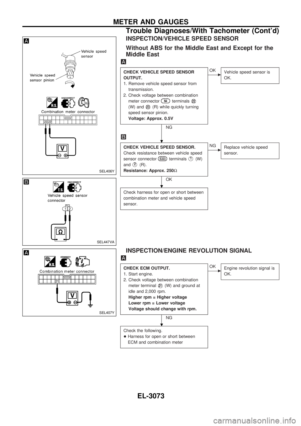
INSPECTION/VEHICLE SPEED SENSOR
Without ABS for the Middle East and Except for the
Middle East
CHECK VEHICLE SPEED SENSOR
OUTPUT.
1. Remove vehicle speed sensor from
transmission.
2. Check voltage between combination
meter connector
N4terminalsV22
(W) andV23(R) while quickly turning
speed sensor pinion.
Voltage: Approx. 0.5V
NG
cOK
Vehicle speed sensor is
OK.
CHECK VEHICLE SPEED SENSOR.
Check resistance between vehicle speed
sensor connector
E223terminalsV1(W)
and
V2(R).
Resistance: Approx. 250W
OK
cNG
Replace vehicle speed
sensor.
Check harness for open or short between
combination meter and vehicle speed
sensor.
INSPECTION/ENGINE REVOLUTION SIGNAL
CHECK ECM OUTPUT.
1. Start engine.
2. Check voltage between combination
meter terminal
V21(W) and ground at
idle and 2,000 rpm.
Higher rpm = Higher voltage
Lower rpm = Lower voltage
Voltage should change with rpm.
NG
cOK
Engine revolution signal is
OK.
Check the following.
+Harness for open or short between
ECM and combination meter
SEL406Y
SEL447VA
SEL407Y
.
.
.
METER AND GAUGES
Trouble Diagnoses/With Tachometer (Cont'd)
EL-3073
Page 1185 of 1306
INSPECTION/FUEL LEVEL SENSOR UNIT
CHECK GROUND CIRCUIT FOR FUEL
LEVEL SENSOR UNIT.
Check harness continuity between fuel
level sensor unit connector
C3terminal
V1(B) and ground.
Continuity should exist.
OK
cNG
Repair harness or connec-
tor.
CHECK GAUGE UNITS.
Refer to EL section ªFUEL LEVEL SEN-
SOR UNITº in original Service Manual
Pub. No. SM7E-0D22G1.
OK
cNG
Repair or replace.
Refer to FE section of Ser-
vice Manual Pub. No.
SM7E-0D22G1.
CHECK HARNESS FOR OPEN OR
SHORT.
1. Disconnect combination connector and
fuel level sensor unit connector.
2. Check continuity between combination
meter terminal
V20(Y/G) and fuel level
sensor unit connector
C3terminal
V3(Y/G).
Continuity should exist.
3. Check continuity between combination
meter terminal
V20(Y/G) and ground.
Continuity should not exist.
OK
cNG
Repair harness or connec-
tor.
Fuel level sensor unit is OK.
SEL639Y
SEL409Y
.
.
.
METER AND GAUGES
Trouble Diagnoses/With Tachometer (Cont'd)
EL-3074
Page 1187 of 1306
Trouble Diagnoses/Without Tachometer
PRELIMINARY CHECK
*1:Meter/Gauge Operation and Odo/
Trip Meter Segment Check in Diagno-
sis Mode (EL-3070)*2:POWER SUPPLY AND GROUND
CIRCUIT CHECK (EL-3077)*3:Symptom Chart (EL-3076)
SYMPTOM CHART
Symptom Possible causes Repair order
One of speedometer/fuel gauge/water
temp. gauge is malfunctioning.1. Sensor signal
- Vehicle speed signal
- Fuel gauge
- Water temp. gauge
2. Unified meter control unit1. Check the sensor for malfunctioning
meter/gauge. INSPECTION/VEHICLE
SPEED SIGNAL (Refer to EL section
ªVehicle speed signalº in original Ser-
vice Manual.)
INSPECTION/FUEL LEVEL SENSOR
UNIT INSPECTION/THERMAL
TRANSMITTER
2. Replace unified meter control unit. Multiple meter/gauge are malfunction-
ing. (except odo/trip meter)
Before starting trouble diagnoses below, perform PRELIMINARY CHECK, EL-3076.
SEL269Y
METER AND GAUGES
EL-3076
Page 1189 of 1306
INSPECTION/VEHICLE SPEED SENSOR
Without ABS for the Middle East and Except for the
Middle East
CHECK VEHICLE SPEED SENSOR
OUTPUT.
1. Remove vehicle speed sensor from
transmission.
2. Check voltage between combination
meter connector
N10terminalsV24
(W) andV37(R) while quickly turning
speed sensor pinion.
Voltage: Approx. 0.5V
NG
cOK
Vehicle speed sensor is
OK.
CHECK VEHICLE SPEED SENSOR.
Check resistance between vehicle speed
sensor connector
E223terminalsV1(W)
and
V2(R).
Resistance: Approx. 250W
OK
cNG
Replace vehicle speed
sensor.
Check harness for open or short between
combination meter and vehicle speed
sensor.
SEL620Y
SEL447VA
.
.
METER AND GAUGES
Trouble Diagnoses/Without Tachometer
(Cont'd)
EL-3078
Page 1190 of 1306
INSPECTION/FUEL LEVEL SENSOR UNIT
CHECK GROUND CIRCUIT FOR FUEL
LEVEL SENSOR UNIT.
Check harness continuity between fuel
level sensor unit connector
C3terminal
V1(B) and ground.
Continuity should exist.
OK
cNG
Repair harness or connec-
tor.
CHECK GAUGE UNITS.
Refer to EL section ªFUEL LEVEL SEN-
SOR UNITº in original Service Manual
Pub. No. SM7E-0D22G1.
OK
cNG
Repair or replace.
Refer to FE section of Ser-
vice Manual Pub. No.
SM7E-0D22G1.
CHECK HARNESS FOR OPEN OR
SHORT.
1. Disconnect combination connector and
fuel level sensor unit connector.
2. Check continuity between combination
meter terminal
V35(Y/G) and fuel level
sensor unit connector
C3terminal
V3(Y/G).
Continuity should exist.
3. Check continuity between combination
meter terminal
V35(Y/G) and ground.
Continuity should not exist.
OK
cNG
Repair harness or connec-
tor.
Fuel level sensor unit is OK.
SEL639Y
SEL621Y
.
.
.
METER AND GAUGES
Trouble Diagnoses/Without Tachometer
(Cont'd)
EL-3079
Page 1246 of 1306

System Description
FUNCTION
Multi-remote control system has the following function.
+Door lock
+Door unlock
+Hazard reminder
LOCK OPERATION
When the LOCK signal is input to multi-remote control unit (the antenna of the system is combined with
multi-remote control unit), ground is supplied
+through multi-remote control unit terminal
V5
+to smart entrance control unit terminalV4.
Then smart entrance control unit supplies power and ground to each door lock actuator.
UNLOCK OPERATION
When the UNLOCK signal is input to multi-remote control unit (the antenna of the system is combined with
multi-remote control unit), ground is supplied
+through multi-remote control unit terminal
V6
+to smart entrance control unit terminalV5.
Then smart entrance control unit supplies power and ground to each door lock actuator.
HAZARD REMINDER
When the doors are locked or unlocked (signal from driver's door unlock sensor) by multi-remote controller,
power is supplied
+through multi-remote control unit terminals
V3andV8
+to the hazard warning lamps
Then hazard warning lamp flash as follows.
+Lock operation: Flash once
+Unlock operation: Flash twice
MULTI-REMOTE CONTROLLER ID CODE ENTRY
A maximum of four remote controllers can be entered. Any attempt to enter a remote controller will erase
all ID codes previously entered. Therefore, be sure to receive all remote controllers from the vehicle owner
when any ID code entry is performed.
To enter ID code entry, the following signals must be input to the multi-remote control unit.
+Ignition switch ON signal
+Battery power supply
+Signal from remote controller
For detailed procedure, refer to ªID Code Entry Procedureº in EL-3139.
MULTI-REMOTE CONTROL SYSTEM
EL-3135